Why Do LEDs Need a Resistor? The I-V Curve Explained

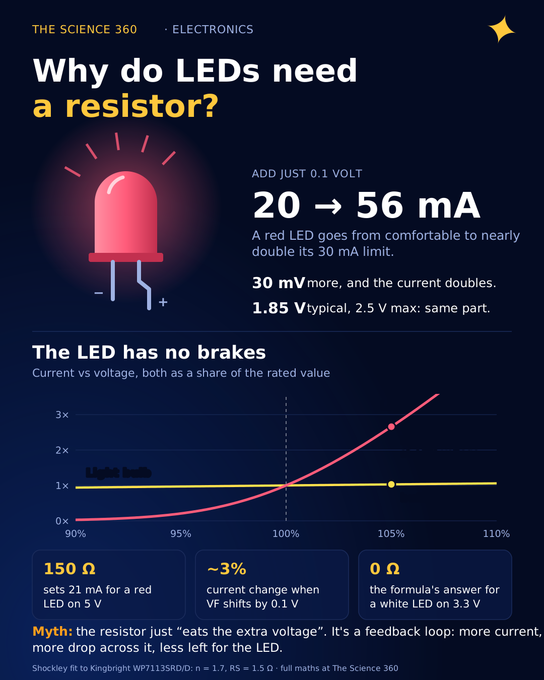
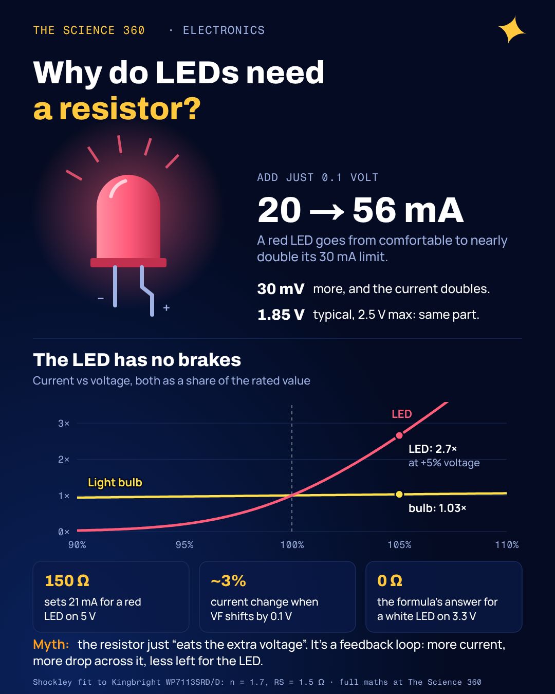
Take a standard 5 mm red LED, the Kingbright WP7113SRD/D. Its datasheet says it draws 20 mA at a typical forward voltage of 1.85 V. Raise the voltage across it to 1.95 V, a change you could not see on a cheap multimeter's last digit, and our model of its measured curve says the current jumps to about 56 mA. The part's absolute maximum DC rating is 30 mA. A tenth of a volt took it from comfortable to overloaded.
A 6 V torch bulb does nothing of the sort. Feed it 5% too much voltage and it draws about 3% more current. That contrast is the whole story of why LEDs need a resistor, and it is worth seeing properly, because the usual explanation ("the resistor drops the extra voltage") misses what is going on.
Why does an LED need a resistor when a light bulb doesn’t?
Both are lamps you connect to a voltage. The difference is in how their current responds when that voltage changes, which is what an I-V curve shows. Figure 1 puts both on the same normalized axes: voltage as a fraction of the rated voltage, current as a fraction of the rated current.
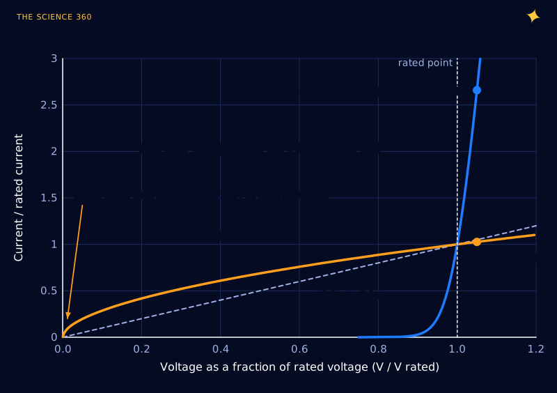
The tungsten filament is self-correcting. Its resistance rises with temperature: tungsten's resistivity at 2,700 K is about 14.3 times its room temperature value, according to the tabulated data compiled by the Physics Factbook. So a cold filament has roughly 1/13 to 1/15 of its working resistance. Push more voltage in, the filament gets hotter, its resistance climbs, and the extra current is mostly cancelled. That is negative feedback built into the metal. It is also why bulbs tend to fail at switch-on, when the cold filament gulps an inrush current of roughly ten times its running current or more.
An LED has the opposite personality. Below about 1.6 V the red LED barely conducts at all. Above that, current climbs exponentially and nothing inside the device pushes back. Worse, as we will see, heating makes it conduct more, not less. The bulb is its own current regulator. The LED needs one bolted on.
How steep is an LED’s I-V curve, in numbers?
The physics is the Shockley diode equation. For forward voltages well above a few tenths of a volt:
is taken at 25 °C. is the ideality factor: 1 to 2 for most silicon and red LEDs, higher for blue and white InGaN parts.
To get n for a real part, I fitted the equation, plus a small internal series resistance RS, to the forward-current graph in the WP7113SRD/D datasheet (which reads about 1.70 V at 1 mA, 1.82 V at 10 mA and 1.90 V at 30 mA). The best fit is n = 1.7 and RS = 1.5 Ω. Now the worked calculation:
Step 1. Pure exponential term, +0.1 V
Step 2. Current doubles every
Step 3. Include the 1.5 Ω internal resistance
At 1.95 V the model solves to 56 mA (2.8× the 20 mA rating, 1.9× the 30 mA maximum). At 2.05 V it gives 105 mA.
The internal resistance tames the curve somewhat (9.9× becomes 2.8×), but only somewhat. Compare a resistor, where 5% more voltage means exactly 5% more current, and the tungsten bulb, where it means 2.6%. For the LED it means 166%.
White LEDs are softer. The WP7113QWC/D white LED's curve (about 2.55 V at 1 mA, 3.25 V at 20 mA, 3.5 V at 30 mA) fits n ≈ 3.6 with roughly 22 Ω of internal resistance. A blue or white InGaN die with a high ideality factor is consistent with measurements: a TU Graz student lab measured n = 2.39 for a white LED and 3.43 for a blue one. So 0.1 V extra pushes a white LED from 20 mA to only about 24 mA. That gentler slope is why people get away with mistakes on white LEDs that would kill a red one, and it explains why coin-cell "throwies" work at all.
The misconception: “the resistor drops the extra voltage”
Almost every tutorial frames it this way: your supply is 5 V, the LED "needs" 2 V, so the resistor "eats" the other 3 V. The arithmetic is right. The mental model is wrong in a way that matters.
An LED does not need a voltage. It needs a current, and its voltage is a consequence of that current, its temperature and the particular die you happened to buy. The datasheet does not even pin it down: the WP7113SRD/D lists 1.85 V typical and 2.5 V maximum at 20 mA. You cannot "give the LED 1.85 V" because you do not know which LED you have, and because 1.85 V on a warm one is a different current than 1.85 V on a cold one.
The better model: the resistor is a current sensor and regulator in one. Any rise in current raises the voltage across the resistor, which leaves less for the LED, which pulls the current back down. The resistor turns the LED's steep exponential into the gentle slope of Ohm's law. In control terms, it is negative feedback with a loop gain set by R compared with the LED's own dynamic resistance (about 3.6 Ω for our red LED at 20 mA).
A second myth falls out for free: the resistor does not have to be on the anode side. Series current is the same everywhere in the loop, so a resistor on the cathode limits it identically.
How do you calculate the LED resistor value?
The formula everyone uses is fine, as long as you check the worst case afterwards:
Example 1: red LED from 5 V at 20 mA
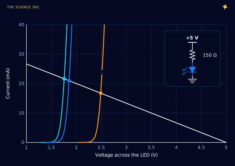
150 Ω is the nearest E12 value. The 16.7 mA line is for a 2.5 V maximum- LED (model: 16.8 mA). A 1/8 W or 1/4 W resistor is plenty, and the LED stays well under its 75 mW rating.
The load line in Figure 2 shows why the result is robust. The resistor's straight line crosses all three LED curves within a few milliamps of each other, even though the curves themselves are spread across 0.75 V.
Example 2: red LED from a 3.3 V microcontroller pin at 10 mA
is read from the datasheet graph. Current: 10.0 mA for a typical part, 5.8 mA for a 2.5 V maximum part.
Ten milliamps is bright for a modern indicator, and it keeps you well inside the pin limits of a typical microcontroller. The ATmega328P on an Arduino Uno, for example, has an absolute maximum of 40 mA per I/O pin, and the pin's own output resistance (tens of ohms) adds a little extra limiting that you should not rely on.
Example 3: white LED from 5 V at 20 mA
Current: 20.6 mA for a typical part, 14.2 mA for a 4.0 V maximum part.
Why a white LED on 3.3 V is a trap
Run Example 3 on a 3.3 V rail and the formula gives . That is the formula telling you there is no headroom left for regulation. Connect the LED directly and you get 20 mA from a typical part, about 24 mA from one 0.1 V lower, and about 1 mA from one at the 4.0 V maximum. Nothing is setting the current except the LED's own spread.
The general rule is a one-line sensitivity estimate. If the LED's forward voltage shifts by (part-to-part spread or temperature), the current shifts by roughly:
The full model gives 3.1% and 6.6% for the red cases. For the white LED the simple formula breaks down; the LED's internal resistance holds the change to 15.5%.
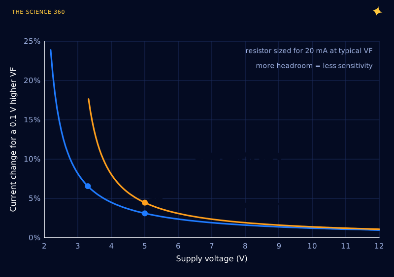
A useful rule of thumb from this curve: give the resistor at least as much voltage as the LED, and the current will hold within a few percent. If your supply cannot do that, it is time for a current-source driver.
How temperature turns a small error into thermal runaway
A diode's forward voltage at fixed current falls as it warms. Kingbright specifies the temperature coefficient of VF as −1.9 mV/°C for the red WP7113SRD/D and −3.0 mV/°C for the white WP7113QWC/D. Here is what that does with and without a resistor.
Junction 30 °C warmer than 25 °C, red LED
Driven at a fixed 1.85 V (no resistor): model current 38.7 mA (was 20 mA), +94%.
Driven from 5 V through 150 Ω:
The 3.6 Ω is the LED's dynamic resistance.
Now close the loop. More current means more heat, which lowers VF, which raises the current further. With a fixed voltage the loop gain can exceed one, and the LED runs away until it is limited by its own internal resistance or something breaks. With a resistor the loop gain is tiny. This is the second job of the resistor, and it is the one that bites people who "tested it at room temperature and it was fine".
Why do LEDs in parallel need separate resistors?
Parallel LEDs share a voltage, and we have just seen that a shared voltage is the worst way to drive an exponential device. Figure 4 compares two red LEDs of the same part number whose forward voltages differ by 0.1 V, a difference well inside the datasheet's 1.85 V typical to 2.5 V maximum spread.
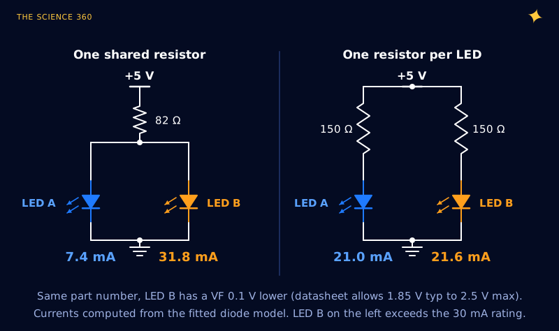
The shared resistor still regulates the total current well. It just has no say in how that total divides, and the division is set by the exponential curves. Sweep the mismatch and the picture gets clearer:
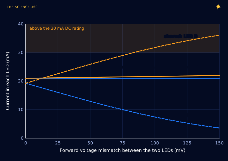
Every 10 mV of mismatch moves about 1.3 mA from one LED to the other, and 10 mV is the shift from a 5 °C temperature difference. To be fair to the other side: Analog Devices notes that modern LEDs of the same type and manufacturer are often matched well enough that resistors can be omitted with negligible intensity mismatch in many cases. That is a statement about brightness matching at low current, not a guarantee against overstress. Separate resistors cost a cent each. Use them, or put the LEDs in series, where the same current flows through all of them by definition.
When should you use a constant-current LED driver instead?
A resistor is a crude current source: good when the supply has plenty of headroom and wastes no more than you can afford. In Example 1 the resistor burns 66 mW to deliver 39 mW to the LED, so 37% efficiency. That is irrelevant for an indicator and unacceptable for a 3 W lighting LED.
Use a proper current source when:
- Headroom is small, as with white LEDs on 3.3 V or a long series string close to the supply voltage. A two-terminal linear regulator such as onsemi's NSI45020 holds about 20 mA across a wide voltage range and turns on with only about 0.5 V across it.
- Power is high. Above roughly half a watt of LED power, a switching constant-current driver (a buck converter that regulates current instead of voltage) is more efficient and keeps the junction cool.
- Brightness must match across many LEDs, as in displays and backlights. Multi-channel sink drivers set every channel's current from one reference resistor.
- The supply varies, as with a car's nominal 12 V rail, which sits well above 12 V whenever the alternator is charging.
For dimming, change the duty cycle (PWM) rather than the resistor. The LED sees either its design current or zero, so its colour stays put and the resistor math above still holds.
FAQ
Can you connect an LED without a resistor?
Only if something else limits the current, such as a constant-current driver, a coin cell with high internal resistance, or a supply that is current-limited. Connected straight to a stiff voltage source, a red LED's current rises about threefold for every 0.1 V above its rated forward voltage, so it will usually overheat or degrade quickly.
Does the resistor go before or after the LED?
It does not matter. In a series circuit the same current flows through every element, so a resistor on the anode side and a resistor on the cathode side limit the current identically. Choose whichever side makes the layout or switching easier.
What resistor do I need for an LED on 5V?
Use R = (supply voltage minus LED forward voltage) divided by the desired current. For a red LED (about 1.85 V) at 20 mA that is (5 minus 1.85) / 0.020 = 157 ohms, so 150 ohms is the nearest common value. For a white LED (about 3.3 V) it is 85 ohms, so use 82 ohms.
Can I use one resistor for several LEDs in parallel?
It is a bad idea. Small forward voltage differences between LEDs make the current split unevenly. With a 0.1 V mismatch between two red LEDs sharing one resistor, one LED can take about 32 mA and the other about 7 mA. Give each LED its own resistor, or put the LEDs in series.
What happens if the LED resistor value is too high?
Nothing harmful: the LED simply runs at lower current and looks dimmer. Modern indicator LEDs are often perfectly visible at 2 to 5 mA, so erring high is the safe direction.
Related on The Science 360
Sources
- Kingbright, WP7113SRD/D 5 mm super bright red LED datasheet (VF 1.85 V typ, 2.5 V max at 20 mA; TC of VF −1.9 mV/°C; IF 30 mA max; forward current graph): kingbrightusa.com/images/catalog/SPEC/WP7113SRD-D.pdf
- Kingbright, WP7113QWC/D 5 mm white LED datasheet (VF 3.3 V typ, 4.0 V max at 20 mA; TC of VF −3.0 mV/°C): kingbrightusa.com/images/catalog/SPEC/WP7113QWC-D.pdf
- The Physics Factbook, "Resistivity of Tungsten" (table of resistivity from 300 K to 3,600 K, after T. W. Zerda, TCU): hypertextbook.com/facts/2004/DeannaStewart.shtml
- Shockley diode equation and ideality factor: en.wikipedia.org/wiki/Shockley_diode_equation
- TU Graz, "I/V curve measurement of different types of diodes" (fitted ideality factors 2.39 white, 3.43 blue): lampz.tugraz.at/~hadley/semi/studentreports/ws22/blue_white_leds/Diode_LED.html
- Analog Devices, "Driving LEDs with push-pull port expander outputs" (resistors and current balancing): analog.com technical article PDF
- Pololu blog, LEDs in parallel and series resistors: pololu.com/blog/9
- Arduino Playground, ATmega328P pin current limitations (40 mA per I/O pin absolute maximum): arduino.cc/playground/Main/ArduinoPinCurrentLimitations
- onsemi NSI45020 constant current regulator, 20 mA, 45 V: octopart.com/part/onsemi/NSI45020T1G
Method note: LED curves are a Shockley-equation fit (with series resistance) to the manufacturer's typical forward-current graphs at 25 °C. Individual parts differ; the worst-case checks above use datasheet maximums.
Header image: NASA (image KSC-2014-2868), regraded for this article.