How do you read a resistor color code?
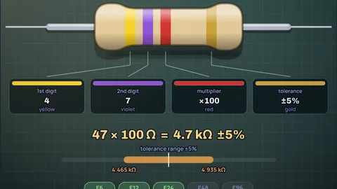
Hold the resistor so the band that stands apart from the others (usually gold or silver) is on the right, then read left to right. On a 4 band resistor the first two bands are digits, the third is the multiplier and the fourth is the tolerance. Yellow, violet, red, gold is 4, 7, ×100, ±5%: 4.7 kΩ, anywhere from 4.465 kΩ to 4.935 kΩ. A 5 band resistor has three digits before the multiplier, and a 6 band one adds a temperature coefficient at the end.
The colours run in rainbow order: black 0, brown 1, red 2, orange 3, yellow 4, green 5, blue 6, violet 7, grey 8, white 9. Gold and silver only appear as a multiplier (×0.1, ×0.01) or a tolerance (±5%, ±10%). Tap a band in the simulator to change it, or type a value to see its bands. For the chart and the mnemonic, see the resistor color code chart post, and for a resistor you are about to buy, the LED resistor calculator picks one.
Key results
- 4 band: digit, digit, multiplier, tolerance. Red red brown gold = 22 × 10 = 220 Ω ±5%.
- 5 band: three digits, so 1% values like 4.99 kΩ can be marked. Brown black black brown brown = 100 × 10 = 1 kΩ ±1%.
- 6 band: a 5 band code plus a temperature coefficient. A red sixth band means 50 ppm/K, so a 100 kΩ part drifts about 250 Ω over a 50 °C rise.
- Real values are standard values: 4.7 kΩ, 220 Ω and 10 kΩ are all in the E6 series. If you decode something like 5 kΩ, you have probably read it backwards; the nearest E24 value is 5.1 kΩ.
Six resistors worth knowing
Each section decodes one resistor band by band with the numbers the simulation shows, and has a button that loads it. Together they cover every rule you need.
Yellow, violet, red, gold: 4.7 kΩ
4 band, ±5%Yellow is 4, violet is 7, so the significant figures are 47. Red as a multiplier means ×100, which gives 4700 Ω, written 4.7 kΩ or 4K7 on a schematic. Gold in the last place is ±5%, so a good part measures between 4.465 kΩ and 4.935 kΩ.
This is the most common pull-up value in hobby electronics, which is why it is worth recognising on sight. The pull-up resistor guide explains why 4.7 kΩ and 10 kΩ turn up on almost every I2C bus and button input.
Red, red, brown, gold: 220 Ω
4 band, ±5%Red red is 22. Brown as a multiplier is ×10, so one zero: 220 Ω. The trap is the third band: brown here does not mean the digit 1, it means "add one zero". Read it as a digit and you get 221, which is not a value anyone makes.
220 Ω is the LED resistor in nearly every Arduino kit. With a red LED on 5 V it gives about 14 mA, see what resistor for an LED on Arduino. Its neighbour 330 Ω is Orange, Orange, Brown, Gold.
Brown, black, orange, gold: 10 kΩ
4 band, ±5%Brown black is 10, and orange multiplies by 1000: 10,000 Ω or 10 kΩ. A quick way to remember the multiplier band: it is the number of zeros. Orange is 3, so three zeros after 10.
Do not confuse it with brown, black, red (1 kΩ) or brown, black, yellow (100 kΩ). The only difference is the multiplier colour, and under a yellowish lamp red and orange can look alike. When in doubt, measure with a multimeter before soldering.
Brown, black, black, brown, brown: 1 kΩ at 1%
5 band, ±1%Five bands mean three significant figures. Brown black black is 100, brown multiplier is ×10, so 1000 Ω. The last brown is ±1%: 990 Ω to 1.01 kΩ. Precision metal film resistors like this usually have a blue or light blue body, which the simulator copies.
The extra digit is what lets 1% resistors use the E96 series, where values like 4.99 kΩ (Yellow, White, White, Brown, Brown) exist. There are 96 E96 values in each decade against 12 in E12. Brown at both ends is the classic reading-direction puzzle: read backwards it gives brown brown black black, 110 Ω, which is also a real value. The wider gap before the tolerance band is the only printed clue, so measure the part if the gap is unclear.
Six bands: 100 kΩ, 1%, 50 ppm/K
6 band, ±1%, temperature coefficientBrown black black orange is 100 × 1000 = 100 kΩ. Brown tolerance is ±1%. The sixth band, red, is the temperature coefficient: 50 ppm/K, meaning the resistance changes by 50 parts per million for every degree of temperature change.
Over a 50 °C rise that is 50 × 50 = 2500 ppm, or 0.25%, about 250 Ω on 100 kΩ. You only care in measurement circuits, references and filters. Brown (100 ppm/K) is the most common sixth band.
Gold and silver multipliers: 0.47 Ω
4 band, fractional valuesValues below 10 Ω need a multiplier smaller than 1. Gold is ×0.1 and silver ×0.01. Yellow, violet, silver, gold is 47 × 0.01 = 0.47 Ω, written R47 on schematics. You find these as current sense resistors in power supplies and motor drivers.
So gold can appear twice on one resistor: once as a multiplier (third band) and once as the tolerance (fourth). Position tells you which. Yellow, violet, gold, gold would be 4.7 Ω.
Resistor color code chart (IEC 60062)
| Colour | Digit | Multiplier | Tolerance | Temp. coefficient |
|---|---|---|---|---|
| Black | 0 | ×1 | 250 ppm/K | |
| Brown | 1 | ×10 | ±1% | 100 ppm/K |
| Red | 2 | ×100 | ±2% | 50 ppm/K |
| Orange | 3 | ×1,000 | ±0.05% | 15 ppm/K |
| Yellow | 4 | ×10,000 | ±0.02% | 25 ppm/K |
| Green | 5 | ×100,000 | ±0.5% | 20 ppm/K |
| Blue | 6 | ×1,000,000 | ±0.25% | 10 ppm/K |
| Violet | 7 | ×10,000,000 | ±0.1% | 5 ppm/K |
| Grey | 8 | ×100,000,000 | ±0.01% | 1 ppm/K |
| White | 9 | ×1,000,000,000 | ||
| Gold | ×0.1 | ±5% | ||
| Silver | ×0.01 | ±10% | ||
| Pink | ×0.001 |
From IEC 60062:2016. A missing tolerance band means ±20%. Orange, yellow and grey tolerances (±0.05%, ±0.02%, ±0.01%) were added in the 2016 edition; older parts sometimes used grey for ±0.05%. Pink (×0.001) is in the standard but rare.
How the calculator works
The colour table is IEC 60062:2016, the international standard for resistor and capacitor markings. Each colour maps to a digit (0 to 9), a multiplier (a power of ten, plus ×0.1 for gold and ×0.01 for silver), a tolerance and, for the sixth band, a temperature coefficient in ppm/K.
To decode, the calculator joins the digit bands into a number, multiplies by the multiplier band and applies the tolerance: min = R × (1 − tol), max = R × (1 + tol). To encode a typed value, it rounds to two significant figures (4 band) or three (5 and 6 band), picks the multiplier that gives the right number of zeros and keeps your tolerance colour. It accepts 4k7, 4.7k, 2M2, 220 and R47 style input.
It then checks the value against the IEC 60063 preferred number series: E6 (20%), E12 (10%), E24 (5%), E48 (2%) and E96 (1%). Each series spaces values so that neighbouring tolerance ranges just touch. If the value is in none of them, the calculator shows the nearest E24 value (4 band) or E96 value (5 and 6 band), because a non-standard reading almost always means a misread colour or the wrong reading direction.
The drawing uses the real band positions of a through-hole resistor: digit bands grouped toward one end and the tolerance band set apart. Tap a band to step through the colours allowed in that position; gold and silver only appear where the standard allows them.
What the model leaves out
- Colour accuracy: screens and lamps shift colours. Real red, orange and brown bands are hard to tell apart under warm light, and old resistors fade. The drawn colours are idealised.
- Body colour: beige bodies usually mean carbon film (5%) and blue bodies metal film (1%), but manufacturers vary. The simulator follows the common convention.
- Zero ohm links: a single black band marks a 0 Ω jumper. It is not a 4, 5 or 6 band code, so it is not offered.
- SMD resistors: surface-mount parts use printed number codes (103, 4R7, 01C in EIA-96), not colours.
- Military and old codes: some older parts have a fifth band for reliability rate instead of a digit. That convention is not modelled.
Common misconceptions
"The third band on a 4 band resistor is a digit." It is the multiplier: the number of zeros. Red red red is 2200 Ω, not 222 Ω.
"You can read from either end." Only one direction gives a standard value. Brown black orange gold is 10 kΩ; read backwards (gold first) it is nonsense, because gold is never a digit. On 5 band parts with brown at both ends both directions can give real values, so look for the gap or measure.
"Gold is always tolerance." Gold in the multiplier position means ×0.1, so yellow violet gold gold is 4.7 Ω ±5%.
Frequently asked questions
How do you read a 4 band resistor color code?
Put the gold or silver band on the right. The first two bands are digits, the third is the multiplier (number of zeros) and the fourth is the tolerance. Yellow, violet, red, gold is 47 × 100 = 4.7 kΩ ±5%.
What is the difference between 4, 5 and 6 band resistors?
A 4 band resistor has two digits, a multiplier and a tolerance. A 5 band resistor has three digits, so it can mark precision values like 4.99 kΩ, usually with 1% tolerance. A 6 band resistor adds a temperature coefficient band at the end.
What is the color code for a 10k resistor?
Brown, black, orange, then the tolerance band (gold for ±5%). On a 5 band 1% resistor it is brown, black, black, red, brown. Both read as 10 kΩ.
Which side of a resistor do you start reading from?
Start from the end where the bands are bunched together. The tolerance band, often gold or silver, is set slightly apart at the other end. If you are unsure, read both ways: only one direction gives a standard value such as 4.7 kΩ or 10 kΩ.
What does a gold or silver band mean?
In the last position, gold means ±5% tolerance and silver ±10%. In the multiplier position, gold means ×0.1 and silver ×0.01, used for resistors under 10 Ω.
Keep learning
Resistor Color Code Chart and a Mnemonic That Works
A clear resistor color code chart for 4, 5 and 6 band resistors, a mnemonic built on the rainbow, worked examples and a table of common values.
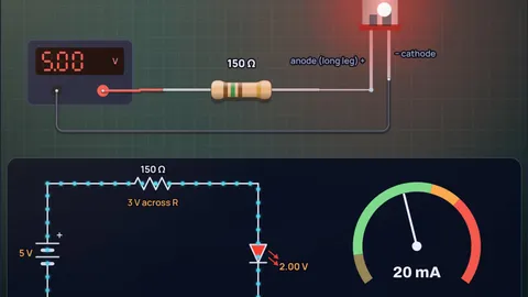
What Resistor for an LED on Arduino 5V and 3.3V?
Resistor values for every LED colour on Arduino 5V and ESP32 3.3V pins, with the pin limits, worked examples and why a white LED on 3.3V is a trap.

How to Choose a Pull-Up Resistor Value (With I2C Math)
Pull-up resistors have a minimum set by sink current and a maximum set by rise time and leakage. Worked I2C example at 400 kHz, plus MCU internal pull-ups.

Why Do LEDs Need a Resistor? The I-V Curve Explained
An LED's current rises exponentially with voltage: 0.1 V extra takes a red LED from 20 mA to 56 mA. Here is the physics, the resistor math and the fixes.