What Resistor for an LED on Arduino 5V and 3.3V?
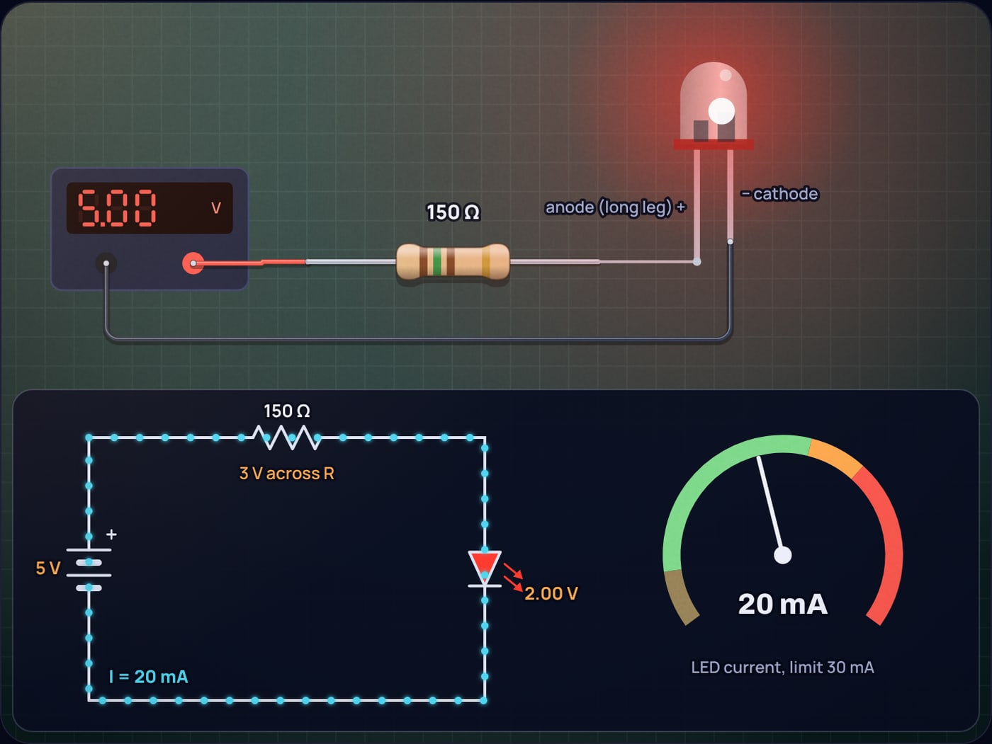
Every Arduino starter kit ships the same bag: a handful of 5 mm LEDs and a strip of 220 Ω resistors. On a 5 V Uno that pairing gives a red LED about 14 mA, which is right. Move the same LED and resistor to a 3.3 V ESP32 and the red LED drops to about 6 mA. Swap in a white LED and it gets about 1.5 mA, a dim glow that makes people think the board is faulty. The resistor did not change. The headroom did.
This post gives you the resistor for every common LED colour on 5 V and 3.3 V pins, shows the two calculations behind the table, and explains why a white LED on 3.3 V has no good answer. Each number comes from the LED resistor calculator, which solves the circuit for the standard resistor you will actually use and shows the LED glowing at that current.
How do you calculate the LED resistor?
The LED holds roughly its forward voltage . Whatever is left of the supply sits across the resistor, and Ohm's law turns that leftover voltage into a current:
Then round up to the next standard resistor value, so the current lands at or just under your target. Rounding down pushes it over. The resistor's power is , and you want a part rated for at least twice that.
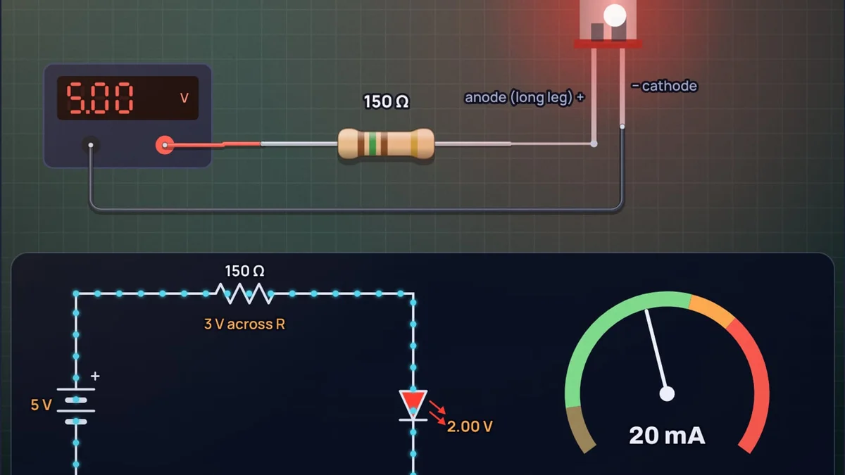
Example 1: red LED on an Arduino Uno pin
150 Ω is a standard E12 value, so no rounding is needed. A 1/8 W (125 mW) or 1/4 W resistor has plenty of margin. With the kit's 220 Ω instead, the LED's voltage settles at about 1.98 V and the current is (5 minus 1.98) divided by 220, about 13.7 mA.
What forward voltage does each LED colour have?
The colour of an LED is set by its semiconductor, and the semiconductor sets the forward voltage. Red, orange and yellow LEDs are AlGaInP or GaAsP and sit near 2 V. Blue, white and modern bright green LEDs are InGaN and sit near 3.2 V. White LEDs are blue LEDs with a phosphor coat, so they share blue's voltage. The physics of that gap is in why blue LEDs need more voltage.
Typical figures from Kingbright's 5 mm datasheets: the WP7113ID high efficiency red is 1.9 V typical at 10 mA (about 2.0 V at 20 mA), the WP7113YD yellow 1.95 V at 10 mA, the WP7113NT pure orange 2.05 V at 20 mA, the WP7113VGC-Z InGaN green 3.2 V and the WP7113QWC/D white 3.3 V, both at 20 mA. Cree's C503D-WAN white is sold in voltage bins from 2.8 V to 4.0 V. The table below uses 2.0 V, 2.1 V and 3.2 V. One trap: old yellowish green LEDs are GaP parts with about 2.1 V, so a "green LED" can mean either. A multimeter's diode test settles it in seconds.
LED resistor values for Arduino 5V and 3.3V
The values below are the next E12 resistor at or above the formula, with the current the circuit then really draws. The model includes the small shift of LED voltage with current, which is why a 330 Ω resistor gives 9.2 mA rather than exactly 10.
| LED colour | Vf | 5 V, 20 mA | 5 V, 10 mA | 5 V, 5 mA | 3.3 V, 10 mA | 3.3 V, 5 mA |
|---|---|---|---|---|---|---|
| Red | 2.0 V | 150 Ω (20.0 mA) | 330 Ω (9.2 mA) | 680 Ω (4.5 mA) | 150 Ω (8.9 mA) | 270 Ω (5.1 mA) |
| Orange | 2.0 V | 150 Ω (20.0 mA) | 330 Ω (9.2 mA) | 680 Ω (4.5 mA) | 150 Ω (8.9 mA) | 270 Ω (5.1 mA) |
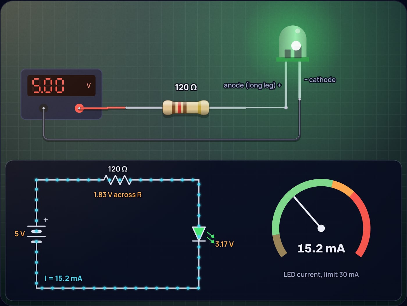
| Yellow | 2.1 V | 150 Ω (19.3 mA) | 330 Ω (8.9 mA) | 680 Ω (4.4 mA) | 120 Ω (10.3 mA) | 270 Ω (4.7 mA) |
| Green (InGaN) | 3.2 V | 100 Ω (18.1 mA) | 180 Ω (10.3 mA) | 390 Ω (4.9 mA) | not reliable | not reliable |
| Blue | 3.2 V | 100 Ω (18.1 mA) | 180 Ω (10.3 mA) | 390 Ω (4.9 mA) | not reliable | not reliable |
| White | 3.2 V | 100 Ω (18.1 mA) | 180 Ω (10.3 mA) | 390 Ω (4.9 mA) | not reliable | not reliable |
Every resistor in the table dissipates 60 mW or less, so any 1/8 W or 1/4 W through-hole part works. For a status LED, 5 mA is usually plenty: modern indicator LEDs are clearly visible at that current, and a lower current keeps the chip cooler when several pins are lit. The 20 mA column is for when you want the LED as bright as its rating allows.
How much current can an Arduino pin give an LED?
The ATmega328P datasheet lists 40 mA per I/O pin and 200 mA through the chip's VCC and GND pins, but both are in the Absolute Maximum Ratings table. That table is where the chip starts to get damaged, not where you should run it. The useful numbers are in the DC characteristics: with 20 mA flowing out of a pin at 5 V, the pin is guaranteed to stay above 4.2 V. That means a pin behaves like a 5 V source with up to about 40 Ω of resistance inside it.
Add that hidden 40 Ω to the 150 Ω resistor and the worst-case current falls from 20 mA to about 16 mA. Typical chips sag less, so real LEDs land between those two numbers. Either way, the conclusion is to design for 10 to 20 mA per LED and count the total: ten LEDs at 20 mA is 200 mA, right at the chip's limit. If you need more, an LED driver or a transistor switch is the clean fix. The same pins also need resistors as inputs, which the pull-up resistor guide covers.
The ESP32 datasheet is more generous on paper: up to 40 mA per pin at maximum drive strength with the output held above 0.8 × 3.3 V = 2.64 V. Espressif also notes that the available current drops as more pins source current at once. Treat 10 mA per LED as a comfortable design value on any 3.3 V board.
Why is a white LED on 3.3V a problem?
This is the case that catches people, so it is worth doing the calculation with real spread.
Example 2: white LED on an ESP32 pin at 10 mA
Only 0.1 V is left for the resistor. Now take two white LEDs from the same bag, one at 3.0 V and one at 3.6 V, both well inside a typical datasheet's range. With the same 10 Ω resistor the model gives:
A factor of about 40 between two "identical" LEDs. On a 5 V supply with 100 Ω the same spread gives 20 mA and 14 mA, a 30 percent difference, because the resistor has 1.8 V to work with instead of 0.1 V.
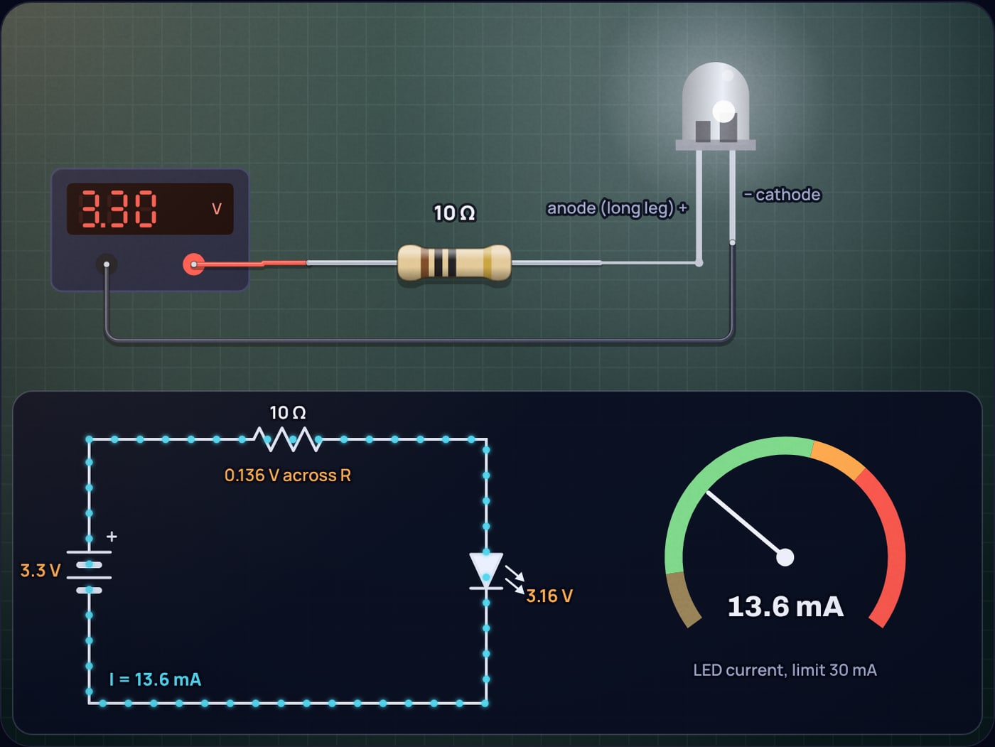
The resistor is supposed to set the current. With 0.1 V across it, the LED's own forward voltage sets it instead, and that varies from part to part and falls as the LED warms. Projects get away with it because the pin's output resistance adds some limiting, which is why a white LED straight on an ESP32 pin often "works". It works by accident.
Three honest fixes:
- Use a red, orange or yellow LED: 150 Ω gives 8.9 mA on 3.3 V with 1.3 V across the resistor.
- Power the LED from the 5 V (USB) rail and switch it with an NPN transistor or a small logic-level MOSFET. The pin then only supplies a fraction of a milliamp.
- Use a constant-current LED driver if brightness matters, for example in a display or a lamp.
What about 12V, LED strips and higher supplies?
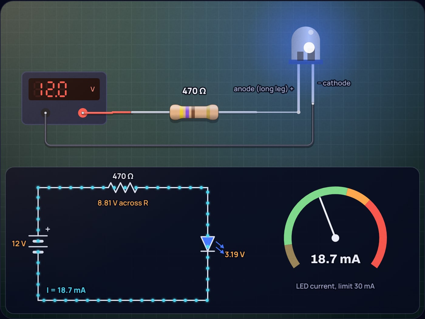
Higher supplies give the resistor more voltage to work with, so the current is very stable, but the resistor now does most of the work and gets warm. A blue LED on 12 V at 20 mA needs 440 Ω by formula, 470 Ω in practice, giving 18.7 mA. The resistor dissipates about 165 mW, more than the LED, so a 1/8 W part would run hot. Use 1/2 W. Better still, put three blue LEDs in series: 12 minus 9.6 leaves 2.4 V, so about 120 Ω and three times the light for the same current.
What happens if you get the resistor wrong?
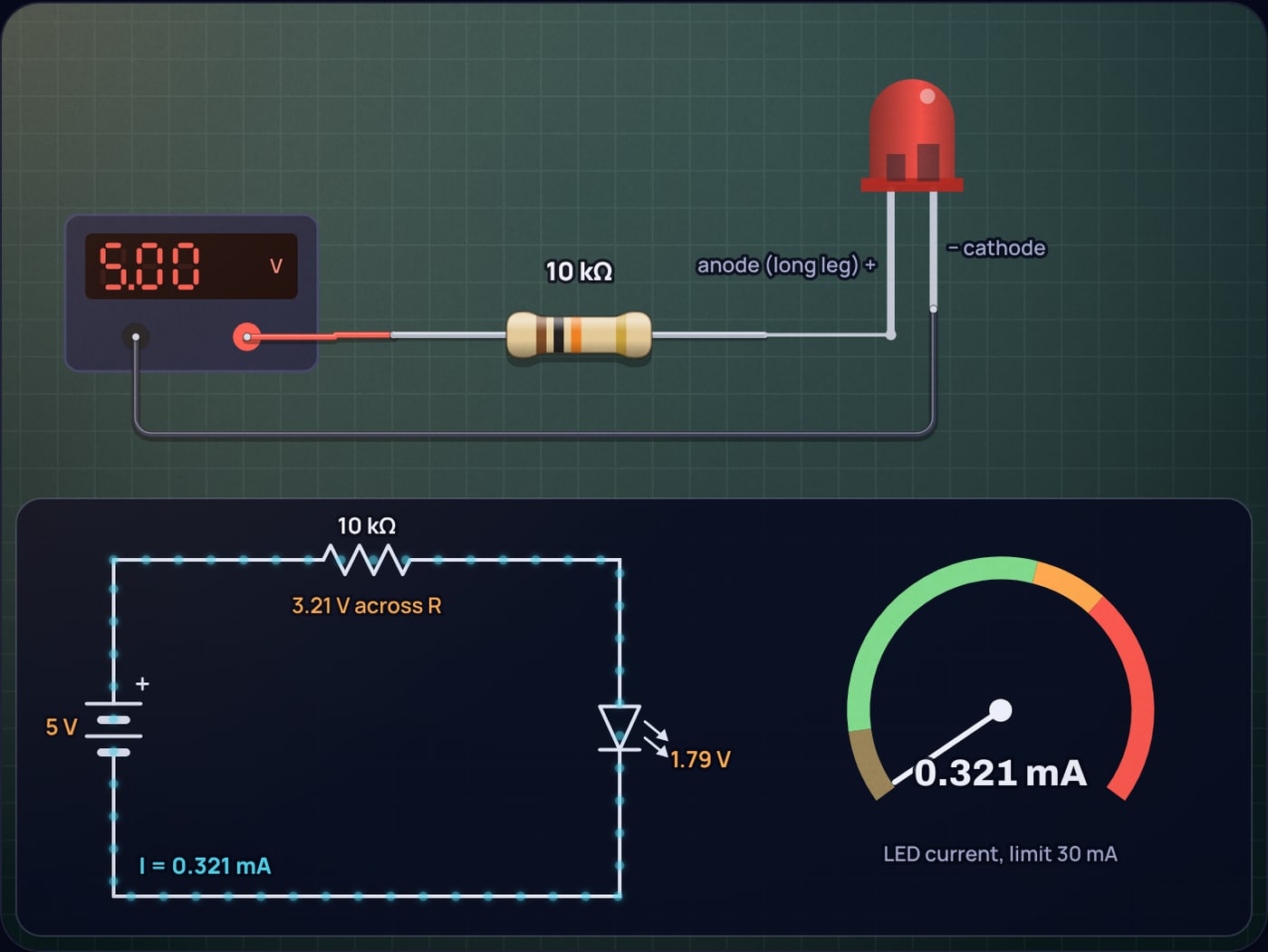
Too big is harmless. A 10 kΩ resistor (brown black orange) picked by mistake gives a red LED on 5 V about 0.32 mA, a faint glow. If an LED lights weakly, check the bands first: it is almost always the resistor, not the LED. The resistor colour code calculator reads them for you.
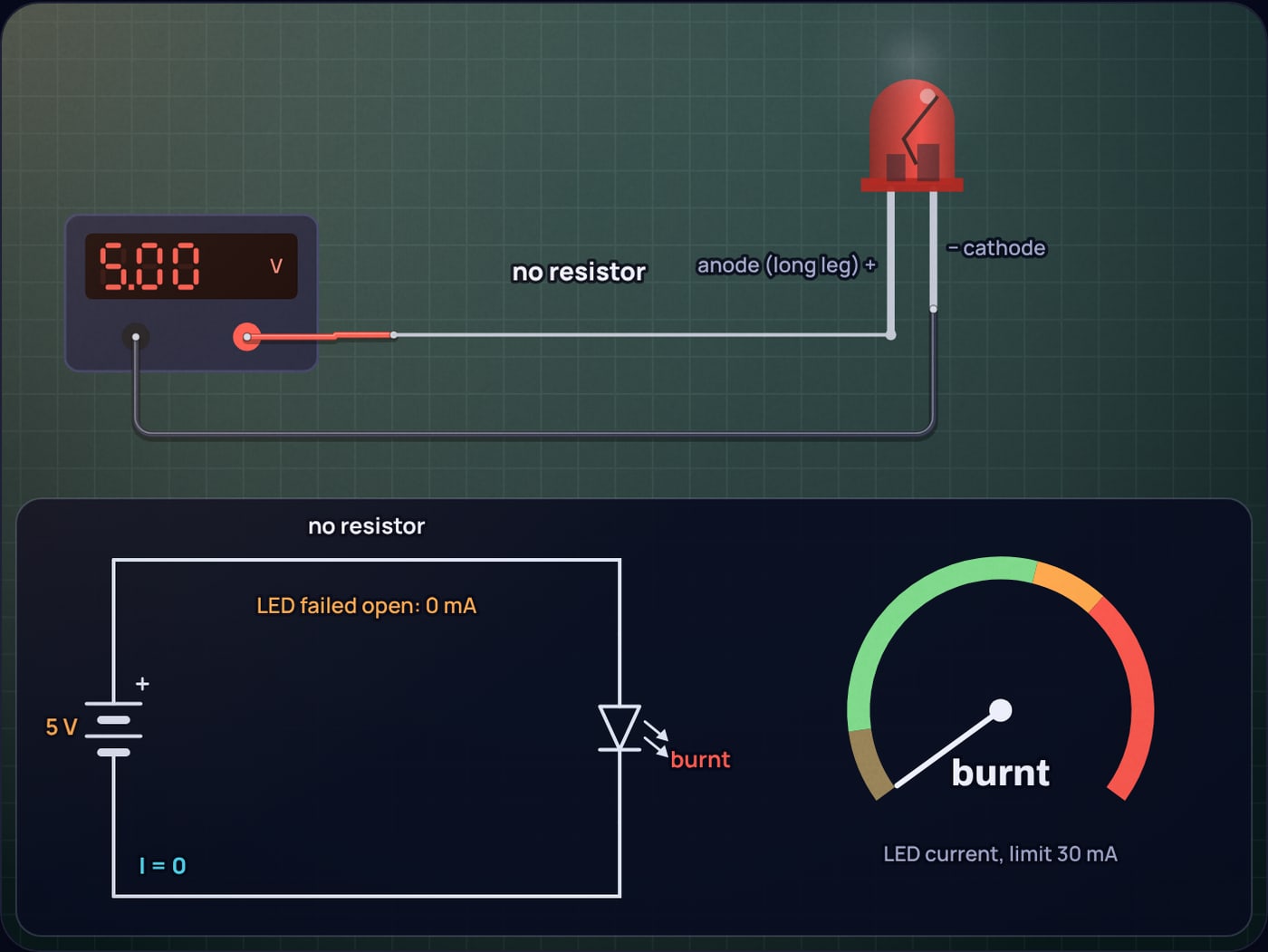
Too small, or none at all, is the dangerous direction. An LED's current rises exponentially with voltage, so without a resistor nothing in the circuit sets the current except the supply's limit and the wiring. On a bench supply the LED flashes and dies. On an Arduino pin the pin's own resistance limits it to tens of milliamps, which overstresses both the pin and the LED and shortens their lives. The full explanation with I-V curves is in why LEDs need a resistor.
Common mistakes with Arduino LEDs
- Thinking the resistor must go on the positive side. It does not matter. A series loop carries one current, so the resistor works the same between pin and LED or between LED and GND.
- Sharing one resistor between parallel LEDs. Small forward voltage differences make one LED take most of the current. Give each LED its own resistor.
- Using PWM as a reason to skip the resistor. During each pulse the LED sees the full pin voltage. PWM changes how long the pulses are, not how much current flows in them.
- Getting the LED backwards. The long leg is the anode and goes toward the positive side. The flat on the rim marks the cathode. A reversed LED simply stays dark at these voltages.
Try it yourself
Open the 3.3 V white LED setup in the simulator and move the supply slider slowly from 3.3 V up to 5 V. The resistor value climbs from 10 Ω to 100 Ω, and the current gauge stops jumping around as the headroom grows. Then type 220 into the custom resistor box and switch between colours to see what a single kit resistor does to each LED.
Sources
- Microchip, ATmega48A/PA/88A/PA/168A/PA/328/P datasheet, Absolute Maximum Ratings (40 mA per I/O pin, 200 mA VCC and GND) and DC Characteristics (VOH 4.2 V minimum at 20 mA, VCC = 5 V): microchip.com ATmega328P datasheet
- Espressif, ESP32 Series Datasheet, DC characteristics (VOH 0.8 × VDD, IOH 40 mA at maximum drive strength): espressif.com/sites/default/files/documentation/esp32_datasheet_en.pdf
- Kingbright, WP7113ID 5 mm high efficiency red LED (VF 1.9 V typical, 2.3 V maximum at 10 mA; 30 mA DC forward current): kingbrightusa.com WP7113ID
- Kingbright, WP7113QWC/D 5 mm white LED (VF 3.3 V typical, 4.0 V maximum at 20 mA): kingbrightusa.com WP7113QWC/D
- Kingbright, WP7113VGC-Z 5 mm InGaN green LED (VF 3.2 V typical at 20 mA): kingbrightusa.com WP7113VGC-Z
- Kingbright, WP7113NT 5 mm pure orange LED (VF 2.05 V typical at 20 mA): kingbrightusa.com WP7113NT
- Kingbright, WP7113YD 5 mm yellow LED (VF 1.95 V typical at 10 mA): kingbrightusa.com WP7113YD
Frequently asked questions
What resistor should I use for an LED on an Arduino Uno?
For a red, orange or yellow LED, 220 ohms is the practical choice: about 14 mA, bright and well inside the pin’s limits. 150 ohms gives the full 20 mA. For a blue, white or bright green LED, 100 ohms gives about 18 mA and 150 ohms about 12 mA.
What resistor should I use for an LED on an ESP32 or Raspberry Pi Pico?
On a 3.3 V pin, use 150 ohms for a red, orange or yellow LED (about 9 mA). For white, blue or bright green LEDs there is only about 0.1 V of headroom, so no resistor value gives a predictable current. Use a red LED, or switch the LED from 5 V with a transistor.
Is 220 ohm or 330 ohm better for an Arduino LED?
Both are fine for a red LED on 5 V. 220 ohms gives about 14 mA and 330 ohms about 9 mA. Brightness looks similar because the eye responds roughly logarithmically, so 330 ohms is a good default when you drive several LEDs at once.
How much current can an Arduino pin supply for an LED?
The ATmega328P datasheet gives 40 mA per pin as an absolute maximum, not an operating value, and 200 mA for the whole chip’s supply pins. At 20 mA the pin is guaranteed to stay above 4.2 V. Design for 10 to 20 mA per LED and keep the total well under 200 mA.
Do I need a resistor if I use PWM to dim the LED?
Yes. PWM switches the pin fully on and off, so during each on period the LED sees the full 5 V or 3.3 V. The resistor sets the current during those pulses; PWM only changes how long they last.
- LED resistor calculator Pick a supply, LED colour and current to get the standard resistor, its power rating and the real current, and watch the LED glow, dim or burn out.
- PWM Duty Cycle Simulator: Waveform and Average Volts Drag the duty cycle and frequency and watch the square wave, its average voltage, an LED, a motor and an RC filter respond, plus why 50% duty looks 76% bright.
- Resistor color code calculator Tap the bands of a 4, 5 or 6 band resistor or type a value like 4k7 to get its colours, tolerance range and E12/E24 match, plus a full colour chart.
 555 Timer Frequency Formula: Where 1.44 Comes From
 ADC Resolution vs Accuracy: ENOB, INL and the Reference
