What resistor do you need for an LED?
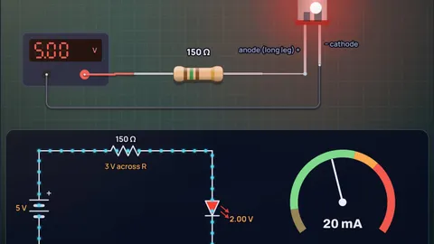
Subtract the LED's forward voltage from the supply and divide by the current you want. A red LED on 5 V at 20 mA needs (5 − 2.0) ÷ 0.020 = 150 Ω, so a 150 Ω resistor rated 1/8 W or more. A white or blue LED on 5 V at 20 mA needs 90 Ω, so use 100 Ω. Always round up to the next standard value: the current then lands at or slightly under your target, never over it.
The calculator does the rounding for you, then solves the real circuit with that standard resistor, because an LED's voltage shifts a little with current. Move the supply slider and watch the LED: it brightens, dims, or burns out exactly as the model predicts. If you want the physics of why the resistor is needed at all, read Why do LEDs need a resistor?, and for the Arduino and ESP32 values in one table, see what resistor for an LED on Arduino 5 V and 3.3 V.
Key results from the calculator
- Red on 5 V: 150 Ω gives 20.0 mA and the resistor warms by 60 mW. A 220 Ω gives 13.7 mA, 330 Ω gives 9.2 mA, and both are still bright.
- White or blue on 5 V: 100 Ω (the next E12 value above 90 Ω) gives 18.1 mA.
- White on 3.3 V: only 0.1 V is left for the resistor, so 10 Ω is all it can take, and the current is set by the LED's own spread, not by the resistor. This is the classic ESP32 trap.
- Blue on 12 V: 470 Ω gives 18.7 mA, but the resistor dissipates 165 mW, so use a 1/2 W part, not a tiny 1/8 W one.
Six setups people actually build
Each section gives the numbers the simulation shows for that setup, explains the choice and has a button that loads it. The LED models use typical forward voltages from 5 mm datasheets at 20 mA.
A red LED on an Arduino Uno pin (5 V)
5 V, red, 20 mAThe textbook case. A red LED drops about 2.0 V, leaving 3.0 V across the resistor. At 20 mA that is 150 Ω, which happens to be a standard E12 value, so the real current is 20.0 mA and the resistor dissipates 60 mW. Any 1/8 W or 1/4 W resistor is fine.
Many kits ship 220 Ω for this job. That gives 13.7 mA, which looks almost as bright, because perceived brightness grows much more slowly than current. The ATmega328P on an Uno is rated 40 mA absolute maximum per pin, so 20 mA leaves margin, but running several LEDs at 20 mA each adds up against the chip's total supply current. The pull-up resistor guide covers the other resistor every Arduino project needs.
A white LED on an ESP32 or Raspberry Pi pin (3.3 V)
3.3 V, white, 10 mAA white LED needs about 3.2 V, so a 3.3 V pin has only 0.1 V to spare. The formula gives 10 Ω for 10 mA, and the model then gives 13.6 mA, more than the target, because the LED's voltage at 10 mA is lower than the 20 mA datasheet figure. A part at the datasheet maximum forward voltage would barely light.
With so little headroom the resistor cannot regulate the current. In practice a GPIO pin's own output resistance limits it, and the result varies from board to board. Better options: drive the LED from 5 V through a transistor, use a red, yellow or orange LED (150 Ω gives 8.9 mA for red), or accept a dimmer LED. The transistor base resistor guide shows the switch circuit.
A blue LED on 12 V (car, solar or LED strip supply)
12 V, blue, 20 mAWith 12 V and a 3.2 V blue LED, the resistor drops 8.8 V. The formula says 440 Ω; the next E12 value up is 470 Ω, giving 18.7 mA. The resistor now turns 165 mW into heat, more than the LED itself, so a 1/8 W part would run hot. The calculator suggests 1/2 W for a 2x margin.
A car's "12 V" is really 12.6 V parked and up to about 14.4 V with the engine running. At 14.4 V the same 470 Ω gives about 23.8 mA, still under the 30 mA limit, which is why you size for the highest voltage you expect. For two or three LEDs, put them in series with one resistor: the wasted power drops a lot. The 12 V wire gauge guide covers the wiring side.
A green LED on 5 V USB at 15 mA
5 V, green, 15 mAModern bright green LEDs are InGaN parts with a forward voltage around 3.2 V, close to blue and white, not the 2.1 V of the old yellowish green GaP LEDs. At 15 mA the formula gives 120 Ω and the next E12 value is 120 Ω, for 15.2 mA.
If your green LED looks yellowish and dim, it is probably a GaP part, and it needs a bigger resistor, closer to the red values. When in doubt, measure the forward voltage with a multimeter's diode test. Why the colours differ is explained in why blue LEDs need more voltage.
What happens with no resistor at all
5 V, red, 0 ΩConnect a red LED straight across a stiff 5 V supply and the model current is astronomically large, because an LED's current grows exponentially with voltage: for this part, about ten times for every 0.12 V. In reality the LED's internal resistance, the wires and the supply's own limit cap it at amps, and the LED dies in a flash. The simulation shows it burnt out and open: 0 mA afterwards.
People get away with it sometimes because the source is weak: a coin cell has tens of ohms of internal resistance, and a microcontroller pin sags under load. Neither is a design. The full story with the I-V curves is in why LEDs need a resistor.
A 10 kΩ resistor by mistake
5 V, red, 10 kΩGrab a brown black orange resistor instead of brown green brown and the LED gets 0.3 mA. It still lights, faintly, which is a useful clue: an LED that glows weakly almost always has too large a resistor, not a fault.
Nothing is harmed. Erring high is the safe direction, and modern indicator LEDs are often visible at 1 to 2 mA. With 1 kΩ you get 3.1 mA, plenty for a power indicator in a dark room. If you are unsure of a resistor's value, read its bands with the resistor colour code calculator.
LED resistor values for every colour at 3.3 V, 5 V and 12 V
| LED colour | Forward voltage | 3.3 V, 10 mA | 5 V, 20 mA | 12 V, 20 mA | Power at 12 V |
|---|---|---|---|---|---|
| Red | 2.0 V | 150 Ω | 150 Ω | 560 Ω | 179 mW |
| Orange | 2.0 V | 150 Ω | 150 Ω | 560 Ω | 179 mW |
| Yellow | 2.1 V | 120 Ω | 150 Ω | 560 Ω | 175 mW |
| Green | 3.2 V | 10 Ω (marginal) | 100 Ω | 470 Ω | 165 mW |
| Blue | 3.2 V | 10 Ω (marginal) | 100 Ω | 470 Ω | 165 mW |
| White | 3.2 V | 10 Ω (marginal) | 100 Ω | 470 Ω | 165 mW |
Next E12 value at or above (Vs − Vf) ÷ I, using typical forward voltages for 5 mm LEDs. Green means modern InGaN green; old GaP green LEDs need about 2.1 V, like yellow. "Marginal" means less than 0.2 V is left for the resistor, so the current is not well controlled.
How the calculator works
The supply, the resistor and the LED are in series, so the same current flows through all three. The LED holds roughly its forward voltage Vf, so the rest of the supply appears across the resistor, and Ohm's law gives the current: I = (Vs − Vf) ÷ R. Turned around, the resistor you need is R = (Vs − Vf) ÷ I.
Resistors are sold in standard values. The calculator rounds up to the next value in the E12 series (10, 12, 15, 18, 22, 27, 33, 39, 47, 56, 68, 82 and their multiples of ten) or E24 if you choose it. Rounding up keeps the current at or below your target.
Then it solves the real circuit. Each LED colour is modelled with the Shockley diode equation, I = I0 × exp(V ÷ (n × Vt)), fitted so it draws 20 mA at its typical forward voltage. The solver finds the current where the supply equals the resistor drop plus the LED drop. That is why the "actual current" can differ a little from the target, and why it matters most when the headroom is small.
Resistor power is P = I² × R. The calculator recommends the smallest common rating (1/8, 1/4, 1/2, 1, 2 or 5 W) that is at least twice the dissipation. The gauge's green zone is 5 to 25 mA; orange is the last stretch before the 30 mA continuous rating typical of 5 mm indicator LEDs; red is over it. Past about 48 mA the model treats the LED as burnt out.
What the model leaves out
- Part-to-part spread: a datasheet "typical" forward voltage can be 0.3 V to 0.7 V below the maximum. The calculator uses the typical value; on a 5 V supply that changes the current by a few percent, on 3.3 V it can change it by half.
- Temperature: forward voltage falls by about 2 to 3 mV per degree as the LED warms, so the current creeps up slightly. A series resistor keeps that in check, which is part of its job.
- The driver: the supply is treated as an ideal voltage. A microcontroller pin has some output resistance (its voltage sags under load), and batteries sag as they drain.
- Brightness: the glow in the picture scales with current. Real perceived brightness grows more slowly, and efficiency differs between colours, so a 5 mA green can look brighter than a 20 mA red.
- High-power LEDs: 1 W and 3 W LEDs run at 350 mA to 700 mA and need constant current drivers and heat sinks, not resistors from this table.
Common misconceptions
"The resistor goes on the positive side." It can go on either side. In a series loop the same current flows everywhere, so a resistor between the LED and ground limits it exactly as well.
"One resistor can serve several LEDs in parallel." It works on the bench but not reliably: tiny forward voltage differences make one LED hog the current. Give each LED its own resistor, or put LEDs in series.
"A bigger resistor protects better, so use 1 kΩ for everything." It is safe, but at 3.3 V a 1 kΩ resistor leaves a white LED with under 0.5 mA, barely lit. Size it for the current you want.
Frequently asked questions
What resistor do I need for an LED on 5V?
For a red, orange or yellow LED at 20 mA, 150 Ω (220 Ω also works and gives about 13.7 mA). For a blue, white or InGaN green LED at 20 mA, 100 Ω. The formula is R = (5 − Vf) ÷ I, rounded up to the next standard value.
What resistor do I need for an LED on 3.3V?
For a red LED at 10 mA, 150 Ω. For a white or blue LED, 3.3 V leaves almost nothing for the resistor (10 Ω or less), so the current is poorly controlled. Use a lower forward voltage colour, or drive the LED from 5 V through a transistor.
Can I use a 220 ohm resistor for any LED?
On 5 V, yes, for indicator LEDs: about 13.7 mA for red and roughly 8 mA for white or blue, all safe and visible. On 3.3 V a 220 Ω resistor gives a red LED about 6 mA and a white LED about 1.5 mA, which is dim. On 12 V it is too small and the LED is overdriven.
What wattage resistor do I need for an LED?
Work out P = I² × R and choose a rating at least twice that. On 5 V at 20 mA that is 60 mW, so 1/8 W or 1/4 W is fine. On 12 V a single LED's resistor dissipates about 165 mW, so use 1/2 W.
What happens if the resistor value is too high?
The LED is dimmer and nothing is harmed. A red LED on 5 V with 10 kΩ still glows faintly at about 0.3 mA. Too low a value is the dangerous direction.
Keep learning
What Resistor for an LED on Arduino 5V and 3.3V?
Resistor values for every LED colour on Arduino 5V and ESP32 3.3V pins, with the pin limits, worked examples and why a white LED on 3.3V is a trap.

Why Do LEDs Need a Resistor? The I-V Curve Explained
An LED's current rises exponentially with voltage: 0.1 V extra takes a red LED from 20 mA to 56 mA. Here is the physics, the resistor math and the fixes.

Why Do Blue LEDs Need More Voltage Than Red?
Blue photons carry 0.8 eV more than red ones, yet blue LEDs need 1.45 V more. Datasheets show where the extra voltage goes and why white LEDs match blue.

Transistor Base Resistor Calculation: Use Forced Beta
Dividing load current by hFE gives a base resistor that leaves many transistors half on. Size it for a forced beta of 10, with worked 2N2222 and BC547 examples.