Why Do Blue LEDs Need More Voltage Than Red?
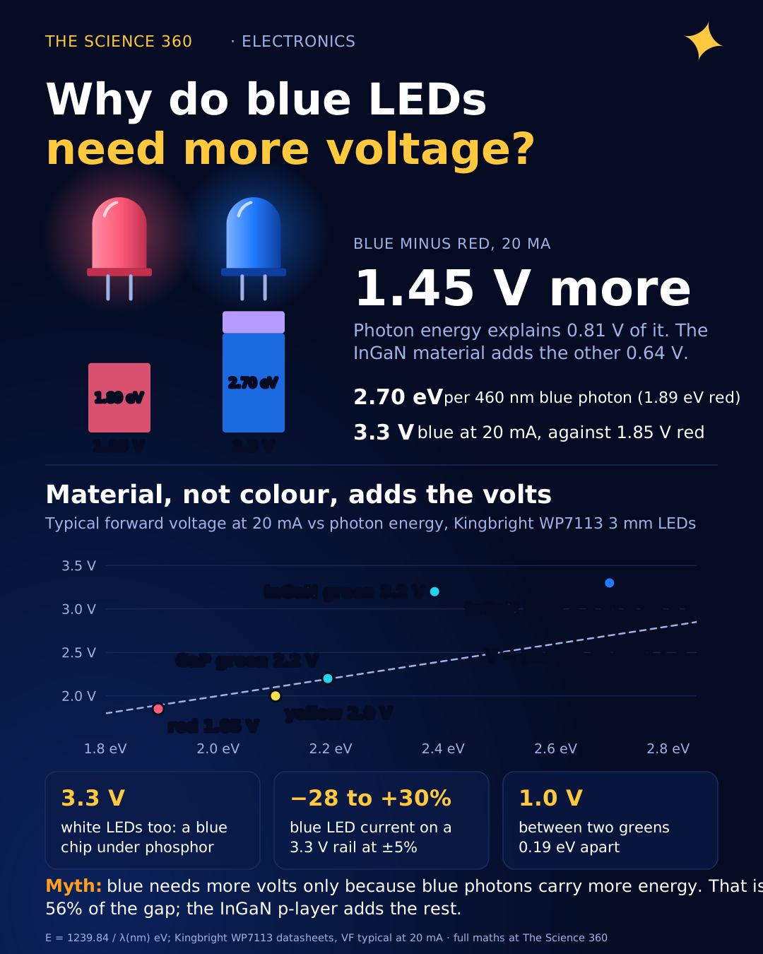
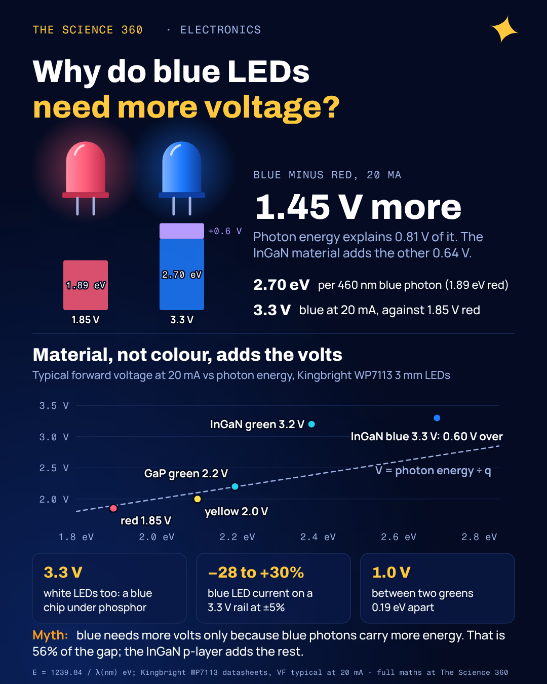
Put two Kingbright 3 mm LEDs side by side on the bench. The red WP7113SRD/D is specified at 1.85 V for 20 mA. The blue WP7113QBC/D, same package, same current, wants 3.3 V. That is a difference of 1.45 V. The photons are different too: 655 nm red light carries 1.89 eV per photon and 460 nm blue carries 2.70 eV, a difference of 0.81 eV. So "blue light has more energy" explains a little more than half the gap. This post accounts for the rest.
Most of what ranks for this question is forum threads that stop at the photon-energy argument. It is the right starting point. It is not the whole answer, and it leaves you unable to explain why a 520 nm green LED needs almost as much voltage as a blue one, or why some red LEDs run below their photon energy.
Why does photon energy set a minimum voltage?
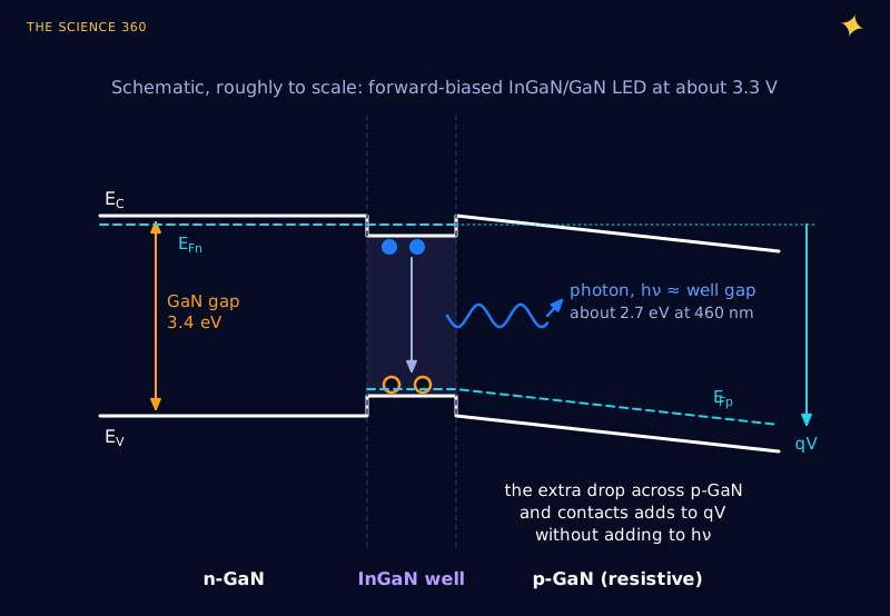
An LED is a p-n junction. Electrons arrive from the n side, holes from the p side, and when an electron falls from the conduction band into a hole in the valence band it can give up the energy difference as a single photon. Voltage is energy per unit charge, so if each electron that crosses the device is to deliver a photon of energy E, the supply has to give each electron roughly that energy: .
The photon energy follows from its wavelength through Planck's relation. With the exact SI values of h, c and q (NIST lists h as 4.135 667 696 × 10−15 eV·s), the product hc is 1239.84 eV·nm, which gives a handy rule:
So the photon-energy floor is about 1.9 V for red and 2.7 V for blue.
The wavelength itself comes from the band gap of the material in the light-emitting layer, so the chain is: material sets band gap, band gap sets photon energy, photon energy sets the minimum voltage. The same physics explains why short-wavelength light behaves so differently in the sky: a blue photon simply carries more energy than a red one.
What do real red, green and blue LEDs measure?
To test the rule, I took eight LEDs from one family, Kingbright's WP7113 3 mm series, so that package, test method and current (20 mA) are the same. Kingbright states each chip's material on its datasheet, which turns out to be the most important column:
The gap column is .
| Part | Material | Peak λ (nm) | Photon (eV) | VF typ (max) | Gap (V) |
|---|---|---|---|---|---|
| SRD | GaAlAs red | 655 | 1.89 | 1.85 (2.5) | −0.04 |
| SEC | AlGaInP red | 640 | 1.94 | 2.2 (2.8) | +0.26 |
| SYD | AlGaInP yellow | 590 | 2.10 | 2.0 (2.5) | −0.10 |
| CGCK | AlGaInP green | 574 | 2.16 | 2.1 (2.5) | −0.06 |
| SGC | GaP green | 565 | 2.19 | 2.2 (2.5) | +0.01 |
| ZGC | InGaN green | 520 | 2.38 | 3.2 (4.0) | +0.82 |
| VBC | InGaN blue | 465 | 2.67 | 3.3 (4.0) | +0.63 |
| QBC | InGaN blue | 460 | 2.70 | 3.3 (4.0) | +0.60 |
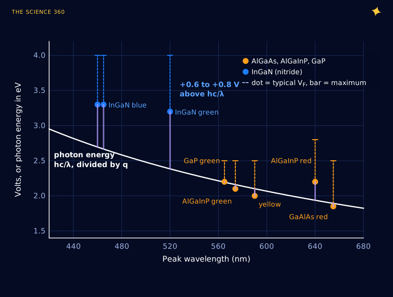
Two families appear. The arsenide and phosphide LEDs (GaAlAs, AlGaInP, GaP) sit within about 0.1 V of the photon-energy line, with one exception at +0.26 V. The nitride LEDs (InGaN) sit 0.6 to 0.8 V above it. Colour alone does not predict that split. The cleanest proof is green: the 565 nm GaP green and the 520 nm InGaN green differ by only 0.19 eV in photon energy but by 1.0 V in forward voltage.
Now redo the red and blue comparison from the opening with the excess separated out:
That is the blue minus red difference in forward voltage, photon energy and material overhead. The photon energy accounts for 56% of the difference and the material overhead for 44%.
Where does a blue LED’s extra 0.6 V go?
The nitride overhead traces back to the same problem that made blue LEDs so hard to invent. The Nobel committee's popular summary of the 2014 physics prize notes that it was "virtually impossible to create p-type layers" in gallium nitride before Akasaki and Amano's work in the late 1980s. Even today p-GaN is a poor conductor. Its usual acceptor, magnesium, sits 140 to 210 meV above the valence band, compared with 12 to 20 meV for the silicon donors used on the n side, according to a 2013 Semiconductor Today review of nitride tunnel junctions. With thermal energy at room temperature only about 26 meV, most magnesium atoms keep their holes, so the layer needs very heavy doping and still has few mobile holes and a high resistivity.
That shows up as series resistance, and you can measure it from the shape of the current-voltage curve. I read six points off each of Kingbright's typical I-V curves for the red SRD and blue QBC, and fitted a standard diode model with an ideality factor n and a series resistance RS:
At 20 mA, I·RS is 0.05 V for red and 0.35 V for blue. The dynamic resistance is 5.8 Ω for red and 23 Ω for blue.
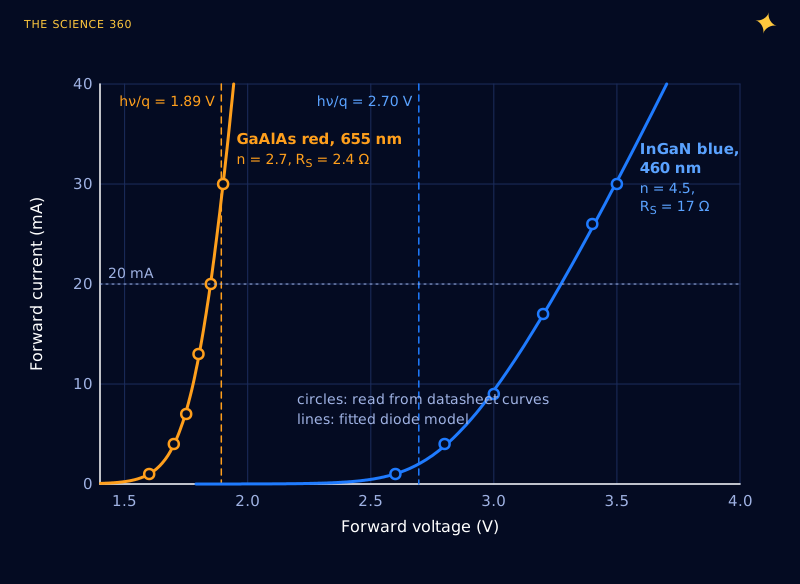
In this model about 0.35 V of the blue LED's 0.6 V excess at 20 mA is plain ohmic drop, and the blue curve in Figure 3 is visibly "lazier" than the red one: it climbs at about a quarter of the slope. The rest of the excess sits in the large ideality factor. An n of 4.5 is not physically "an ideal diode times 4.5"; it lumps together voltage lost across heterojunction barriers, the strong built-in polarization fields of nitride layers, and contacts. The Semiconductor Today article describes those polarization fields as large enough to be used deliberately in tunnel-junction designs.
Can an LED run below its photon energy?
Look at the table again: the GaAlAs red at 1.85 V emits 1.89 eV photons, and the AlGaInP yellow at 2.0 V emits 2.10 eV photons. That looks like free energy. It is not, because the LED is not a closed system. Carriers at room temperature carry thermal energy of order kT on top of the band edge, and the photon emitted when they recombine can take some of that heat with it. The diode current rises exponentially with voltage, so at 20 mA a good junction does not need the full band-gap voltage to inject plenty of carriers.
Pushed to the limit, this becomes a refrigerator. In 2012 Santhanam, Gray and Ram at MIT reported in Physical Review Letters a heated mid-infrared LED (emitting around 2.15 µm) biased below kT/q that emitted 69 pW of light for 29.9 pW of electrical input: a wall-plug efficiency above 200%, with the balance drawn from lattice heat. Practical LEDs are nowhere near that regime, but it settles the principle. hc/λ is a strong guide to forward voltage, not a hard floor.
Why do white LEDs need the same voltage as blue?
Because a white LED is almost always a blue LED. The Nobel summary describes the main method: "use blue light to excite a phosphor so that it shines in red and green". The chip underneath is InGaN, and the datasheets show it: Kingbright's white WP7113QWC/D lists 3.3 V typical and 4.0 V maximum at 20 mA and a VF temperature coefficient of −3.0 mV/°C, identical to the blue QBC. The phosphor does not change the electrical side at all; it only costs some energy as each absorbed blue photon is re-emitted at a longer wavelength.
The same reasoning explains UV and violet LEDs (InGaN or AlGaN, often 3.2 V and up) and the "true green" LEDs used in RGB parts, which are InGaN like the blue die beside them. When you see a datasheet for an RGB LED with red at about 2 V and green and blue both at about 3 V, that is two material systems, not a smooth trend with colour.
Why is a red LED 1.8 to 2.2 V and not one number?
Four separate effects spread the "red LED voltage" across a range:
Chemistry. In the table, the GaAlAs red at 655 nm needs 1.85 V and the AlGaInP hyper red at 640 nm needs 2.2 V. Part of that is the 0.05 eV photon-energy difference; most of it is the material.
Current. In the fitted model the red LED goes from 1.60 V at 1 mA to 1.85 V at 20 mA, and the blue from 2.60 V to 3.27 V. Quoting a single VF without a current is meaningless.
Temperature. Kingbright lists −1.9 mV/°C for the GaAlAs red and −3.0 mV/°C for blue, because band gaps shrink as the crystal warms. Over a 25 to 85 °C range the blue LED's VF falls by .
Unit-to-unit spread. Every datasheet above gives a typical value with a ±0.1 V measurement tolerance and a maximum 0.4 to 0.8 V higher. Your resistor has to work across that range.
What the higher voltage means for your resistor
The extra volt and a half matters most when the supply is not much higher than VF. The series resistor sets the current by dropping the difference, the method covered in why LEDs need a resistor. The smaller that difference, the more any change in supply or VF swings the current.
3.3 V rail, target 10 mA (model VF at 10 mA: red 1.78 V, blue 3.02 V):
With the rail at 3.135 V and 3.465 V (±5%), solving the model gives red 9.1 to 11.2 mA (±10%) and blue 7.3 to 13.2 mA (−28% to +30%). On the same rail, a blue LED 0.2 V above typical gets 6.8 mA instead of 10.2 mA.
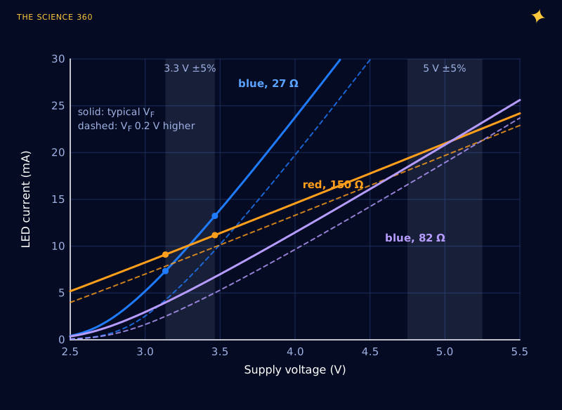
On 5 V the problem goes away: an 82 Ω resistor gives a blue LED 20.8 mA, and a part with VF 0.3 V high still gets 18 mA. So if you drive blue or white LEDs from a 3.3 V microcontroller, either accept the brightness spread, run them from 5 V through a transistor (see transistor base resistor calculation), or use a constant-current driver. Check what your pin can source as well: the limits are in how much current an Arduino pin can supply.
Batteries make it worse. Two alkaline AA cells start near 3.0 V and fall toward 2.2 V. In the fitted model, a blue LED wired straight across them (a bad idea, but a common toy design) draws about 9 mA at 3.0 V, 1 mA at 2.6 V and 0.04 mA at 2.2 V. A red LED, with its knee near 1.6 V, would still be glowing at 2.2 V (and across a fresh pair, with no resistor, would be badly overdriven). That is why single-cell white LED torches contain a small boost converter, and why battery life estimates for LED gadgets depend on the cutoff voltage, not just on mAh.
FAQ
Why do blue LEDs need more voltage than red LEDs?
Each electron passing through an LED can emit at most one photon, so the voltage must be at least the photon energy divided by the electron charge: about 2.7 V for 460 nm blue and 1.9 V for 655 nm red. Blue LEDs are made from InGaN, whose p-type layer is poorly conductive, which adds another 0.6 V or so, giving a typical 3.3 V at 20 mA.
What is the forward voltage of a blue LED?
Typically 3.0 to 3.3 V at 10 to 20 mA for a standard 3 mm or 5 mm InGaN blue LED, with a maximum of about 4.0 V. Kingbright's WP7113QBC/D, for example, is 3.3 V typical and 4.0 V maximum at 20 mA. At 1 mA it is closer to 2.6 V.
Why do white LEDs have the same forward voltage as blue LEDs?
Most white LEDs are blue InGaN LEDs coated with a phosphor that converts part of the blue light to longer wavelengths. The chip, and so the forward voltage, is the same as a blue LED: Kingbright lists 3.3 V typical and 4.0 V maximum at 20 mA for both its blue and white 3 mm parts.
Why do green LEDs have different forward voltages?
There are two kinds. Older yellow-green LEDs (565 to 574 nm) use GaP or AlGaInP and need about 2.1 to 2.2 V. True green LEDs (around 520 nm) use InGaN, like blue LEDs, and need about 3.2 V. The material matters more than the colour.
Can an LED light up below its photon energy?
Yes. Several red and yellow LEDs have typical forward voltages slightly below , and an MIT experiment in 2012 measured an LED emitting more optical power than the electrical power it consumed, with the difference supplied by heat from the crystal.
Related on The Science 360
Sources
- NIST, CODATA value of the Planck constant in eV/Hz (exact, 4.135 667 696 × 10−15 eV·s): physics.nist.gov/cgi-bin/cuu/Value?hev
- Kingbright, WP7113QBC/D blue (InGaN) 3 mm LED datasheet (460 nm, VF 3.3 V typical, 4.0 V maximum at 20 mA, −3.0 mV/°C, typical I-V curve): kingbrightusa.com WP7113QBC-D.pdf
- Kingbright, WP7113SRD/D super bright red (GaAlAs) datasheet (655 nm, 1.85 V typical, 2.5 V maximum, −1.9 mV/°C, typical I-V curve): kingbrightusa.com WP7113SRD-D.pdf
- Kingbright WP7113 datasheets for the remaining parts: SEC-J3 AlGaInP hyper red, SYD AlGaInP yellow, CGCK AlGaInP green, SGC GaP green, ZGC/G InGaN green, VBC/D InGaN blue and QWC/D InGaN white: SEC-J3, SYD, CGCK, SGC, ZGC-G, VBC-D, QWC-D
- Royal Swedish Academy of Sciences, "Popular science background: Blue LEDs, filling the world with new light", Nobel Prize in Physics 2014 (p-type GaN difficulty, white light from blue LED plus phosphor): nobelprize.org popular-physicsprize2014-1.pdf
- M. Cooke, "Lowering tunneling resistance", Semiconductor Today, vol. 8 issue 4, May/June 2013 (Mg acceptor level 140 to 210 meV, Si donor 12 to 20 meV, polarization fields): semiconductor-today.com PDF
- P. Santhanam, D. J. Gray and R. J. Ram, "Thermoelectrically Pumped Light-Emitting Diodes Operating above Unity Efficiency", Phys. Rev. Lett. 108, 097403 (2012) (69 pW out for 29.9 pW in): sclaser.mit.edu PDF
- Physics Forums, "Why do blue LEDs have a higher forward voltage than expected?" (typical page-one discussion): physicsforums.com thread 240105
Method note: Figures 3 and 4 use a diode model, VF = nVTln(I/I0) + IRS, least-squares fitted to six points per LED that I read from Kingbright's typical I-V plots. The fits reproduce the datasheet typical VF to within 0.03 V but are our own approximation, not manufacturer data.
Header image: NASA/Tom Trower (image ARC-2006-ACD06-0036-024), regraded for this article.