What Gauge Wire for 12V? Size for Voltage Drop
Secop, which makes the compressor inside many 12 V camping fridges, publishes a cable table for its BD35F. The compressor draws under 7 A. Ordinary hook-up wire carries 7 A without getting warm. Yet Secop asks for 2.5 mm² cable, about 13 AWG, for a run of just 2.5 m, and 10 mm² for 10 m. That is not overcaution. It is what voltage drop looks like at 12 V, and it is the part most 12 V wire gauge charts quietly get wrong.
Most of the pages that rank for "what gauge wire for 12V" give an ampacity table: so many amps, so many gauge. Ampacity answers "will this wire overheat?" At 12 V the more urgent question is "how many volts will be left at the far end?", and the answer depends on length, which ampacity tables ignore. This post shows how to size 12 V wire from first principles, with the copper resistance worked out from the AWG formula and two real loads.
Why voltage drop matters more at 12 V than at 120 V
A wire's resistance turns current into two things: heat in the wire and lost voltage at the load. Ampacity ratings limit the heat. The heat depends only on current and the wire's resistance per metre, , and it is the same at 12 V as at 230 V. Voltage drop is also , but what matters is the drop as a fraction of the supply. Losing 0.5 V from 230 V is nothing. Losing 0.5 V from 12 V is 4%.
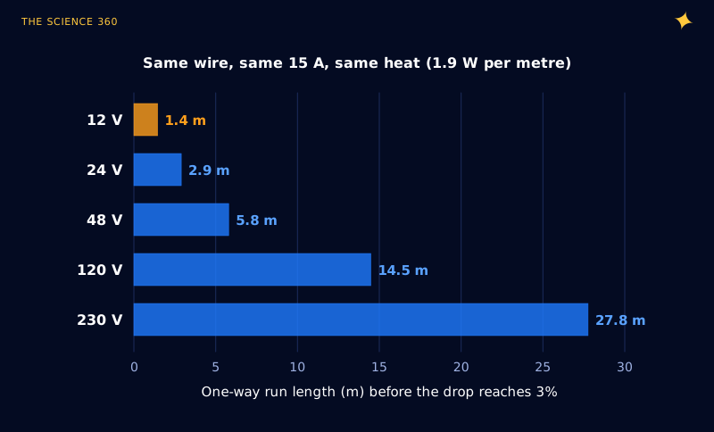
One wire, one current, five supply voltages
14 AWG copper: (derived below). Current: 15 A.
Heat in the wire, whatever the voltage:
One-way length for a 3% drop:
Victron makes the same point in its "Wiring Unlimited" guide with a 2,400 W inverter: 200 A at 12 V loses 0.64 V in two 1.5 m cables of 16 mm², about 5%, while the same load at 48 V draws 50 A and loses 0.3%. Low-voltage systems trade simplicity for fat cable. It is the mirror image of why power lines use high voltage.
How much resistance does each AWG size have?
You do not need a table. The American Wire Gauge is a geometric series defined by two anchor points: 0000 AWG is 0.4600 inch in diameter and 36 AWG is 0.0050 inch, with 39 equal ratio steps between them. NIST's (then NBS) Copper Wire Tables give the ratio as the 39th root of 92, 1.1229 per gauge number. So:
Diameter, area and resistance per metre:
with for annealed copper at 20 °C.
14 AWG:
That is 2.53 Ω per 1,000 ft; NBS table: 2.52.
Two handy consequences fall out of the ratio. Every 3 gauge numbers doubles or halves the area, and so halves or doubles the resistance. Every 6 gauge numbers doubles the diameter. Here are the sizes you will meet in 12 V work:
AWG: area (mm²), resistance (mΩ per metre at 20 °C)
Copper gets more resistive as it warms. NBS gives the temperature coefficient of standard copper as 0.00393 per °C at 20 °C, so a cable at 60 °C (an engine bay, or a wire already near its ampacity) has times its 20 °C resistance, about 16% more. Stranded cable, crimps and fuses add a little more. Victron lists about 0.06 mΩ per cable connection and 0.35 mΩ for a 150 A fuse, small next to a thin wire but not next to a fat one.
Why you have to double the length
The single most common sizing mistake is using the distance from battery to load. Current flows out on the positive wire and back on the negative, and both have resistance. A load 5 m away sits at the end of 10 m of copper. (The exception is a vehicle where the return is the chassis, whose resistance is low but not zero, and whose bolted joints are often the real problem.)
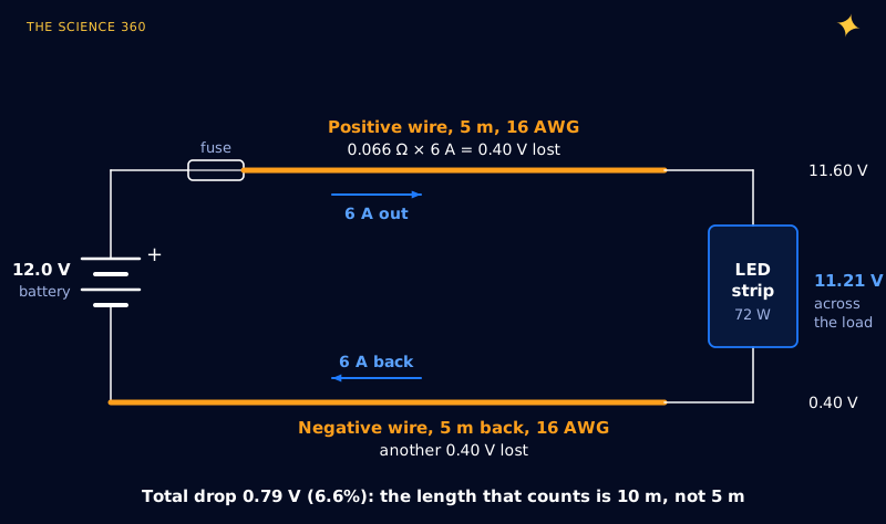
Put that together and you get one formula for the minimum cross-section, which is all a "12 V wire gauge chart" really is:
With copper and a 3% limit at 12 V ():
L = one-way length in metres, I in amps.
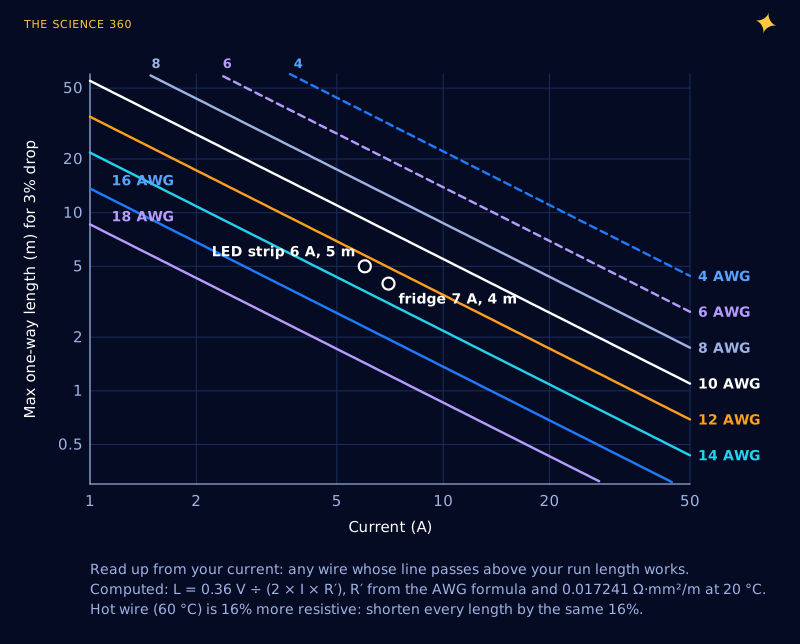
What voltage drop is acceptable: 3%, 2.5% or 10%?
Victron's guide advises "aiming for a voltage drop no bigger than 2.5%", 0.3 V on a 12 V system. Marine practice in North America, following the ABYC E-11 standard as presented in Blue Sea Systems' wire sizing guide, uses 3% for circuits that matter (panel feeds, bilge blowers, navigation lights, electronics) and 10% for everything else, such as general lighting.
Which limit you need depends on how the load reacts to low voltage. A resistive heater just runs a bit cooler. Two common 12 V loads are far less forgiving.
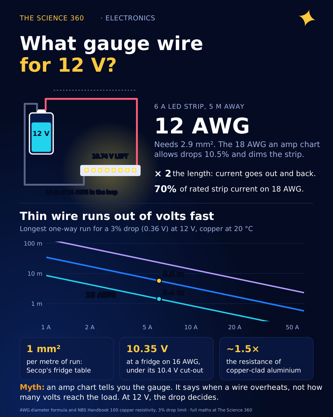
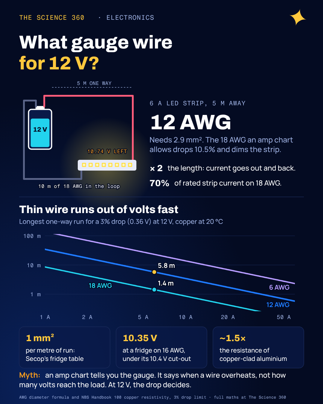
Worked example 1: a 5 m LED strip
Take 5 m of 12 V LED strip rated 14.4 W per metre, 72 W in total, mounted 5 m from the power supply. Current: .
Check each size (round trip 10 m, 6 A):
Heat in 18 AWG at 6 A, barely warm:
An ampacity chart would happily put this strip on 18 AWG. The wire would not get hot. The strip would get dim, and dimmer than the voltage suggests, because of how 12 V strips are built. Most use groups of three LEDs in series with a resistor (the reason is the same as in why LEDs need a resistor). The LEDs take a roughly fixed voltage, so any shortfall in supply comes straight out of the few volts across the resistor.
Our simplified strip model: three white LEDs at 3.0 V each (an assumed value) + resistor, so 9.0 V across LEDs and 3.0 V across the resistor at 12 V.
Strip current scales with , so:
Solving:
Current, and its share of rated current:
A 10% voltage drop turns into a 30% current drop. Real LEDs soften this a little, because their forward voltage falls slightly at lower current, but the leverage is real: three to four times. White LEDs need about 3 V each because of the blue chip inside (see why blue LEDs need more voltage), which is why only three fit under 12 V with so little left for the resistor. The strip's own copper adds a further drop along its length, which is why long strips are fed from both ends.
Worked example 2: a 12 V compressor fridge
The BD35F datasheet lists current at 12 V from 1.51 A at low speed up to 6.85 A at 3,500 rpm. Its battery protection cuts the compressor out at 10.4 V and lets it restart at 11.7 V. The electronic unit can only measure the voltage at its own terminals, so every millivolt lost in the cable is a millivolt closer to cut-out.
Now look at Secop's cable table through the formula. The four entries for 12 V are 2.5 mm² for 2.5 m, 4 mm² for 4 m, 6 mm² for 6 m and 10 mm² for 10 m. Length divided by area is exactly 1 m per mm² every time, which means every entry gives the same voltage drop:
Round-trip resistance (for any row):
At 6.85 A:
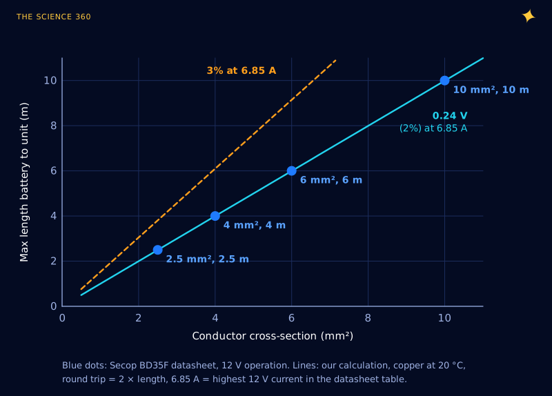
Secop never states its target, but the arithmetic shows it: about 2%, tighter than the 3% rule. Here is what happens if you ignore it for a fridge 4 m from the battery:
Round trip 8 m, 7 A:
Battery sagging to 11.2 V under load, 16 AWG at 60 °C:
That is below the 10.4 V cut-out: the fridge stops while the battery still has charge
That is a common "my fridge keeps cutting out" story, and thicker wire fixes it. Secop's table also lists 2.5 mm² as 12 AWG, which is generous: 12 AWG is 3.31 mm², and 2.5 mm² is closer to 13 AWG. If you buy by AWG, use the table's mm² figure and round up.
When does ampacity win instead?
Ampacity governs short, high-current runs: battery to inverter, battery to starter motor, a 30 A charger lead under a metre long. There the drop is small but the heat is not, and the insulation rating, bundling and engine-bay temperature all reduce what a wire may carry. Size for both and use the bigger wire. The fuse protects the wire, not the load, so its rating must suit the wire you chose.
Watch the metal too. Cheap "copper clad aluminium" (CCA) cable is mostly aluminium, with a copper skin. Aluminium's resistivity is about against copper's in Victron's table, so a CCA wire of the same gauge has roughly 1.5 times the resistance, and a CCA cable must be about one and a half times the area to match. That is a bigger effect than going up one gauge.
A 12 V wire sizing checklist
1. Current: use the maximum the load draws, including motor start if it lasts long enough to matter.
2. Length: (unless you use a chassis return).
3. Drop budget: 2.5 to 3% (0.30 to 0.36 V) for electronics, LEDs, fridges and chargers; up to 10% for non-critical resistive loads.
4. Area: ; add 16% if the cable runs hot.
5. Round up to the next AWG size, then check its ampacity and pick the fuse to protect it.
6. Measure the voltage at the load under full current. A bad crimp can undo everything.
If the numbers come out absurd (a 40 A load 8 m away needs about 31 mm², around 2 AWG), consider moving the battery, splitting the load, or running a higher voltage with a buck converter at the far end. That is the same trade-off Victron describes for inverters, and it is why solar arrays are wired for higher voltage before an MPPT charge controller brings it down. The same physics applies at the smallest scale too: a copper trace on a circuit board is just a very flat wire, as in PCB trace width for current.
FAQ
What gauge wire do I need for 12V?
It depends on current and round-trip length, not on the 12 V. For a 3% drop (0.36 V), the minimum copper cross-section in mm² is . A 6 A load 5 m away needs about 2.9 mm², which is 12 AWG; a 1 A load 2 m away is fine on 20 AWG.
Is 14 gauge wire good for 12V?
For short runs, yes. 14 AWG copper has about 8.3 milliohms per metre. At 10 A it stays within a 3% drop for only about 2.2 m one way; at 5 A, about 4.3 m. Beyond that, the wire is not too hot, but the voltage at the load is too low.
Do you double the length for voltage drop?
Yes, unless the return path is the vehicle chassis. Current flows out on the positive wire and back on the negative, so both wires drop voltage. A load 5 m from the battery has 10 m of wire in its circuit. Blue Sea Systems' charts use round-trip length for this reason.
What is an acceptable voltage drop for 12V?
Victron advises no more than 2.5%, which is 0.3 V at 12 V. Marine practice uses 3% (0.36 V) for critical loads and 10% for non-critical loads such as general lighting. LED strips and compressor fridges need the tighter limit because their performance falls faster than the voltage.
Related on The Science 360
Sources
- NBS (now NIST) Handbook 100, "Copper Wire Tables" (0.017241 Ω·mm²/m at 20 °C, temperature coefficient 0.00393, AWG ratio , resistance table): nvlpubs.nist.gov nbshandbook100.pdf
- Secop, BD35F compressor datasheet, 12 to 24 V DC, 09-2024 (current table to 6.85 A, cut-out 10.4 V and cut-in 11.7 V, DC wire dimensions table): secop.com BD35F datasheet PDF
- Victron Energy, "Wiring Unlimited" (2.5% drop advice, 2,400 W inverter example, resistance of connections and fuses, resistivity table): victronenergy.com Wiring Unlimited PDF
- Blue Sea Systems, "Choosing the Correct Wire Size for a DC Circuit" (3% and 10% categories, round-trip length; seen via search excerpts only): bluesea.com/articles/1437
Method note: all wire resistances are computed from the AWG diameter formula and the IACS resistivity, and checked against the NBS table. The LED strip model (three 3.0 V LEDs plus a resistor per segment, fixed forward voltage) is ours and simplified.
Header image: NASA (image iss038e008291), regraded for this article.