ADC Resolution vs Accuracy: ENOB, INL and the Reference
Plug an Arduino Uno into a laptop, feed analog pin A0 from a precision 2.500 V reference, and print analogRead(A0) * 5.0 / 1023. The ADC has a step size of 4.9 mV, so it feels as if the answer should be within a few millivolts. On a laptop port that happens to sit at 4.80 V, the code comes back around 533 and the sketch prints 2.605 V. That is 105 mV out, more than twenty steps. Nothing is broken. The converter did exactly what its datasheet says; the reading is wrong because of a number that is not in the ADC section at all.
The pages that rank for "ADC resolution vs accuracy" define the two words correctly and then stop at a ruler analogy. What they rarely do is put numbers on a real board, show which error dominates, or explain why averaging a thousand readings will not fix it. That is what this post does.
What is the difference between resolution and accuracy?
Resolution is a counting statement. A 10-bit converter has output codes, so it chops its input range into 1,024 slices. With a 5 V reference, one slice, called one LSB (least significant bit), is . Resolution tells you the smallest change the converter could report.
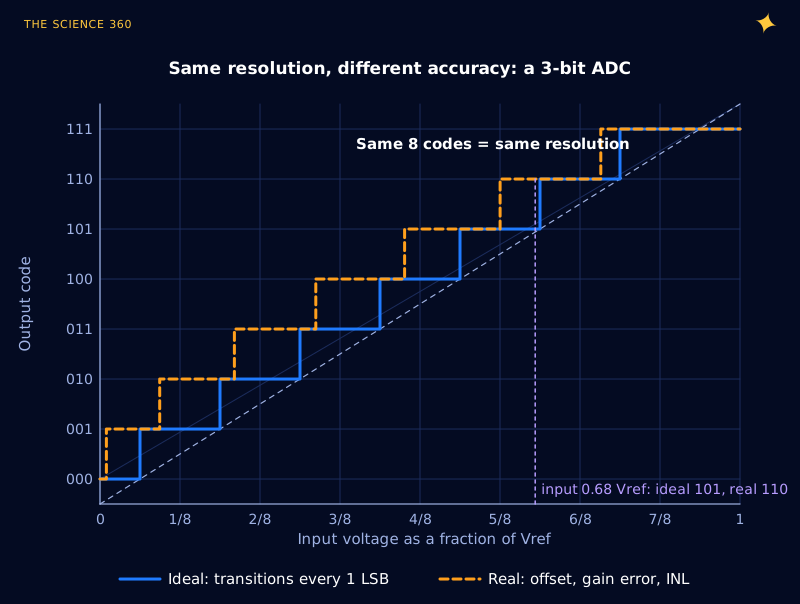
Accuracy is a truth statement: given an input, how far is the reported value from the real one? Figure 1 shows the difference on a toy 3-bit converter. Both staircases have eight codes, so their resolution is identical. The orange one has its transitions in the wrong places, so for an input of 0.68 Vref it reports 110 where the ideal converter reports 101. Same resolution, different accuracy.
A perfect converter still has an error, because it has to round. That quantization error is at most ±0.5 LSB and, for a busy signal, is spread evenly across that range. Its rms value is a standard result:
Quantization error is uniform over , so its mean square is .
For 10 bits at 5 V:
worst case ±2.44 mV
Everything else on the list below adds to that floor, and it usually adds a lot.
Which errors make an ADC inaccurate?
Datasheets split the deviation of a real converter into named pieces. The Microchip ATmega328P datasheet defines them in the same order you would remove them in a calibration:
- Offset error: the first transition (code 0 to 1) happens at the wrong input. The whole staircase is slid sideways.
- Gain error: after removing offset, the last transition is in the wrong place. The staircase is stretched or squeezed.
- INL (integral nonlinearity): after removing offset and gain, the largest distance between an actual transition and the straight line. It describes a bowed or wiggly staircase.
- DNL (differential nonlinearity): the largest deviation of any single step width from the ideal 1 LSB. A DNL of −1 LSB means a step of zero width, a missing code.
- Absolute accuracy or TUE (total unadjusted error): the worst-case combination of everything, including quantization.
Here is what the ATmega328P datasheet (DS40002061B, the commercial part on an Uno) gives, at and a 200 kHz ADC clock:
Absolute accuracy (incl. INL, DNL, quantization, gain, offset): 2 LSB typical
INL: 0.5 LSB typical DNL: 0.25 LSB typical
Gain error: 2 LSB typical Offset error: 2 LSB typical
Internal 1.1 V reference: 1.0 min, 1.1 typical, 1.2 max
Notice that the commercial table lists only typical values. The automotive version of the same chip (document 7810D, −40 to +125 °C) does give limits: absolute accuracy 2.2 LSB typical and 3.5 LSB maximum, gain and offset each within ±3.5 LSB, INL 1.5 LSB maximum. Those are a reasonable guess at what the commercial part guarantees, but it is a guess.
Separately, the Arduino core sets the ADC prescaler to 128 on a 16 MHz board, giving a 125 kHz ADC clock, comfortably inside the 50 to 200 kHz window the datasheet asks for full 10-bit performance. At 13 clocks per conversion that is at most conversions per second.
Why the reference voltage dominates
An ADC does not measure volts. It measures the ratio and reports that ratio as a fraction of 1,024. If Vref is 2% high, every reading is 2% low, and no amount of INL or DNL improvement can fix it. That makes the reference the first thing to look at, and on an Arduino Uno the default reference is the one you would least choose.
In the Arduino AVR core, DEFAULT sets the REFS bits to 01, which the datasheet defines as AVCC, the chip's own 5 V supply. On USB power, that supply is whatever the host port delivers, minus small drops on the board. TI's reference design TIDUF26 summarises the USB 2.0 rule: a 5% tolerance on 5 V, "giving a host voltage range of 4.75 V to 5.25 V", and worst-case cable and connector drops can bring the load down to 4.35 V.
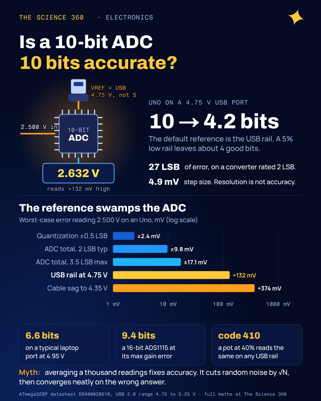
Worked example: reading 2.500 V on a USB-powered Uno. The sketch assumes . The true reference is somewhere else.
:
:
(sagging cable):
In LSB:
against a converter rated at 2 LSB.
Figure 2 stacks these up against the converter's own errors on a log scale. The ADC's datasheet errors are a few millivolts. The reference error is fifty times bigger.
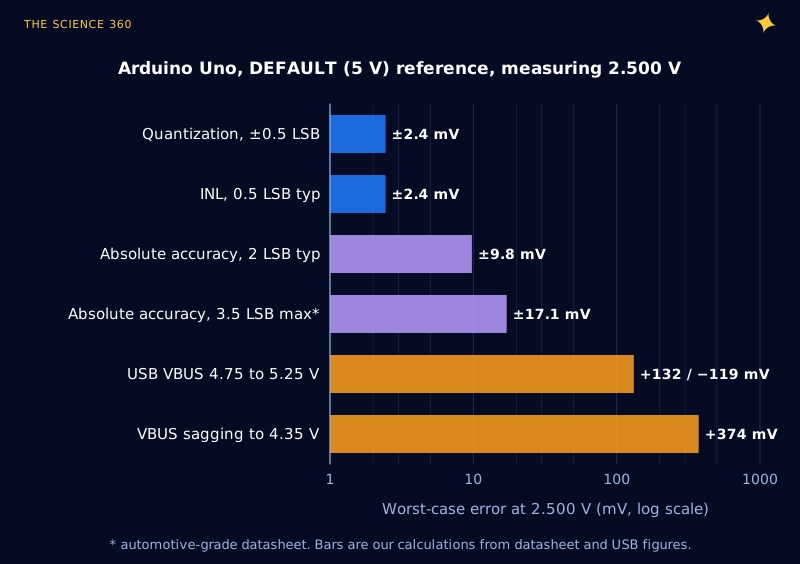
Convert that to "bits of accuracy" and the headline result appears:
of absolute accuracy from a 10-bit converter. Typical laptop port at 4.95 V: error 1%,
The internal 1.1 V reference is not a cure on its own. It is far steadier than a USB supply, but the datasheet allows 1.0 to 1.2 V from chip to chip, ±9%, which is worse than the USB tolerance. What the bandgap gives you is stability: measure its actual value once on your board (for example by reading a known voltage) and store a correction factor, and the large fixed error disappears. A dedicated reference IC on AREF is the cleaner fix if you need absolute accuracy.
When reference error cancels: ratiometric measurements
There is one important case where none of this matters. If the sensor is powered from the same rail as the ADC reference, its output scales with that rail. A potentiometer across 5 V, a resistive divider, a thermistor in a divider (see our NTC thermistor calculation) or a load-cell bridge all produce :
A pot at 40% reads code 410 whether USB delivers 4.75 V or 5.25 V.
This is why hobby projects with pots and thermistors mostly work fine on the default reference, and why the same project reads nonsense when someone uses it to measure a battery voltage. Ask first whether your measurement is ratiometric or absolute. If it is absolute, the reference is your accuracy. The same logic is behind the bridge excitation in our post on how a load cell works.
What is ENOB, and how do you calculate it?
ENOB, the effective number of bits, answers a different question: if this converter were ideal, how many bits would it need to have to produce the same amount of noise and distortion? It is measured dynamically, by feeding in a clean, near full-scale sine wave and taking an FFT of the output.
The starting point is the signal-to-noise ratio of an ideal converter. TI's application report SLAA013, "Understanding Data Converters", derives it from the quantization noise above and a full-scale sine of amplitude :
Turn it around with the measured SINAD (signal to noise and distortion):
Example: a 10-bit ADC measuring :
ENOB is useful because it folds noise, DNL and the harmonic distortion caused by INL into one number. It is not an accuracy figure. A converter with a 5% gain error and a superb SINAD has an excellent ENOB, because gain error only rescales the sine; it does not add noise or distortion. ENOB tells you how finely the converter can see changes. It says nothing about whether the absolute number is right.
Noise alone eats bits in a predictable way. If the input-referred noise is σ LSB rms, it adds to the quantization noise:
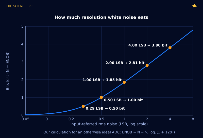
That curve is why a 24-bit delta-sigma part might be specified at 20 effective bits, and why careful datasheets quote "effective resolution" from rms noise. TI's ADS1115 datasheet does exactly that, using , and lists all ranges at the full 16 bits for data rates up to 128 SPS, falling to between 13.8 and 15.1 noise-free bits (from peak-to-peak noise) at 860 SPS.
Is a 16-bit ADC more accurate than a 10-bit one?
The ADS1115 is a good test case, because it is the usual upgrade from an Arduino's built-in ADC. Its LSB on the ±2.048 V range is , eighty times finer than the Uno's. The DC accuracy specifications tell a different story:
Gain error (FSR ±2.048 V, 25 °C): 0.01% typical, 0.15% maximum
At 2.000 V input:
Offset: ±1 LSB typical, ±3 LSB maximum (differential); gain drift up to 40 ppm/°C
Over a 30 °C swing:
extra, another 38 LSB.
Absolute accuracy at the limits:
So at worst-case limits, a 16-bit ADC with an internal reference is a 9-to-10-bit absolute voltmeter before calibration. Typical parts are much better (0.01% typical gain error is about 13 bits), and a two-point calibration against a known voltage removes most of the gain and offset error for that unit at that temperature. What the extra bits really buy you is resolution and low noise: the ability to see a 100 µV change, which is exactly what a bridge sensor needs. That is a real advantage, it just is not the same thing as accuracy.
Does averaging improve ADC accuracy?
Averaging is the most common response to a jumpy reading, and it works, within limits. Microchip's (Atmel's) application note AVR121, "Enhancing ADC resolution by oversampling", gives the standard rules: each extra bit needs 4× as many samples, so n extra bits need samples, and the trick only works if there is noise of at least about 1 LSB to make the last bit toggle. Without noise, every sample returns the same code and the average is just that code.
Random noise of the average:
Uno at 9,615 conversions/s: 12-bit results at 601/s, 14-bit at 37.6/s (fewer with analogRead overhead)
Figure 4 shows a Monte Carlo simulation of this. With no noise at all (orange), averaging does nothing: the error stays at the 0.29 LSB rms quantization floor no matter how many readings you take. With 0.5 or 1 LSB of noise (blue and green), the error falls on a clean line, reaching about 0.01 LSB at 4,096 samples. The purple curve is the crucial one: add a 0.5 LSB fixed error, from INL, offset or the reference, and the average converges beautifully to the wrong answer.
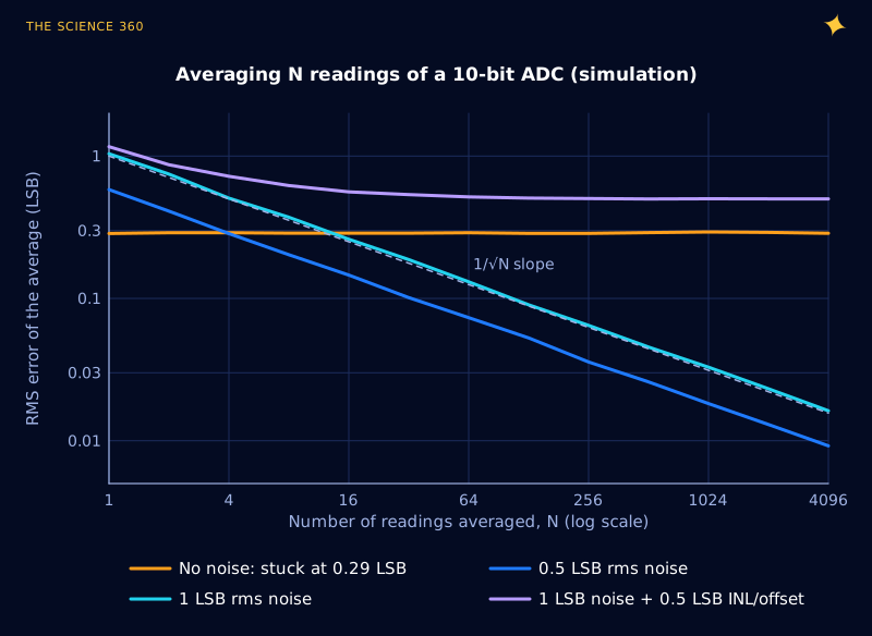
AVR121 says it plainly: oversampling and decimation "will only lower the ADCs quantization error, it does not compensate for the ADCs integral non-linearity." The same is true of offset, gain and reference error, all of which repeat identically in every sample. Averaging buys resolution. Only calibration, or a better reference, buys accuracy.
Two practical notes. First, 1 LSB of noise is often already there on an Arduino, from the supply and the digital core, so averaging usually helps without deliberately added dither. Second, averaging is a low-pass filter. Averaging 256 samples at 9.6 kSPS is a 26.6 ms window, which nulls 37.5 Hz and its multiples; if you want it to reject mains hum, choose a window that is a whole number of mains cycles (20 ms at 50 Hz, 16.7 ms at 60 Hz). And any signal above half the effective sample rate aliases, as explained in our post on the Nyquist theorem and aliasing.
How to get real accuracy out of a microcontroller ADC
Ordered by how much they usually buy you:
- Decide if the measurement is ratiometric. If it is, power the sensor from the ADC's reference and most of the problem disappears.
- Fix the reference. Use a precision reference IC on AREF, or calibrate the internal bandgap once per board. On USB power, never trust the 5 V rail as a reference for absolute readings, especially through a long cable or a USB-C charger whose 5 V may sit anywhere in its tolerance.
- Calibrate offset and gain. Two known inputs, near the bottom and top of the range, let you solve for both and remove them in software.
- Keep the input impedance low. The ATmega328P's sample capacitor charges through your source resistance, and the datasheet says the ADC is "optimized for analog signals with an output impedance of approximately 10 k or less". A high-impedance divider (see why a voltage divider is not a power supply) needs a buffer or a capacitor on the pin.
- Clean the analog supply. Decoupling on AVCC and AREF (our post on the 100 nF decoupling capacitor covers why) and an RC on the input (see RC low-pass filter cutoff) reduce noise before you need to average it away.
- Then average, for resolution and noise.
FAQ
What is the difference between ADC resolution and accuracy?
Resolution is how many output codes the converter has, so it sets the smallest step it can report: 5 V divided by 1,024 is 4.9 mV for a 10-bit ADC. Accuracy is how close the reported value is to the true input. It is set by offset, gain error, nonlinearity, noise and above all the reference voltage, and is usually many LSB worse than the resolution.
How do you calculate ENOB?
Measure SINAD, the ratio of a near full-scale sine to everything else (noise plus distortion), in dB, then . An ideal N-bit converter has , so a 10-bit ADC with 56 dB SINAD has an ENOB of 9.0 bits.
How accurate is the Arduino analogRead?
The ATmega328P converter itself is specified at about 2 LSB typical absolute accuracy, roughly 10 mV with a 5 V reference. But analogRead uses the 5 V supply as its reference by default, and USB allows 4.75 to 5.25 V, so an absolute voltage reading can be off by about 5%, around 125 mV at 2.5 V, unless you calibrate or use a proper reference.
Does oversampling and averaging improve ADC accuracy?
It improves resolution and random noise, not accuracy. Averaging N readings cuts random noise by , and samples give n extra bits, but only if there is at least about 1 LSB of noise to dither the input. Offset, gain error, INL and reference error are the same in every sample, so averaging leaves them untouched.
Is a 16-bit ADC more accurate than a 10-bit ADC?
Not automatically. The 16-bit ADS1115 has a maximum gain error of 0.15% at 25 °C, about 48 of its 62.5 µV LSBs at 2 V, which is roughly 9.4 bits of absolute accuracy before calibration. It resolves far finer steps than a 10-bit part, but its absolute accuracy is only modestly better unless you calibrate it.
Related on The Science 360
Sources
- Microchip, ATmega48A/PA/88A/PA/168A/PA/328/P datasheet DS40002061B (ADC characteristics table 29-15: absolute accuracy 2 LSB typical, INL 0.5, DNL 0.25, gain and offset 2 LSB; internal reference 1.0 to 1.2 V; 50 to 200 kHz clock; 13 cycles per conversion; error definitions): microchip.com DS40002061B
- Microchip (Atmel), ATmega328P automotive datasheet 7810D (absolute accuracy 2.2 typ / 3.5 max LSB, INL 1.5 max, gain and offset ±3.5 LSB): microchip.com 7810D
- Atmel, AVR121, "Enhancing ADC resolution by oversampling" ( samples per n bits, at least 1 LSB of noise, "does not compensate for the ADCs integral non-linearity"): microchip.com AVR121 (doc8003)
- Texas Instruments, SLAA013, "Understanding Data Converters" (derivation of ): ti.com/lit/an/slaa013
- Texas Instruments, ADS111x datasheet SBAS444E (62.5 µV LSB at ±2.048 V, gain error 0.01% typ / 0.15% max, gain drift 40 ppm/°C max, noise and effective resolution tables): ti.com/lit/ds/symlink/ads1115.pdf
- Texas Instruments, TIDUF26 reference design (USB 2.0 host range 4.75 to 5.25 V, worst case 4.35 V at the load): ti.com TIDUF26
- Arduino AVR core source, wiring.c (ADC prescaler 128, 125 kHz at 16 MHz) and Arduino.h / wiring_analog.c (DEFAULT = AVCC reference): github.com/arduino/ArduinoCore-avr
Method note: Figure 1 is an illustrative 3-bit converter with invented errors. Figure 2 and all worked numbers are our arithmetic from the cited datasheet values. Figure 3 uses , which assumes white Gaussian noise and an otherwise ideal converter. Figure 4 is a numpy Monte Carlo of an ideal rounding quantizer.
Header image: NASA/Ken Ulbrich (image AFRC2017-0021-04), regraded for this article.