Can You Use a Voltage Divider as a Power Supply?

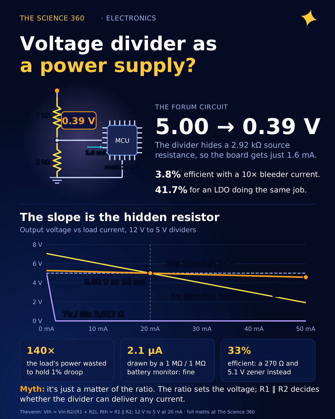
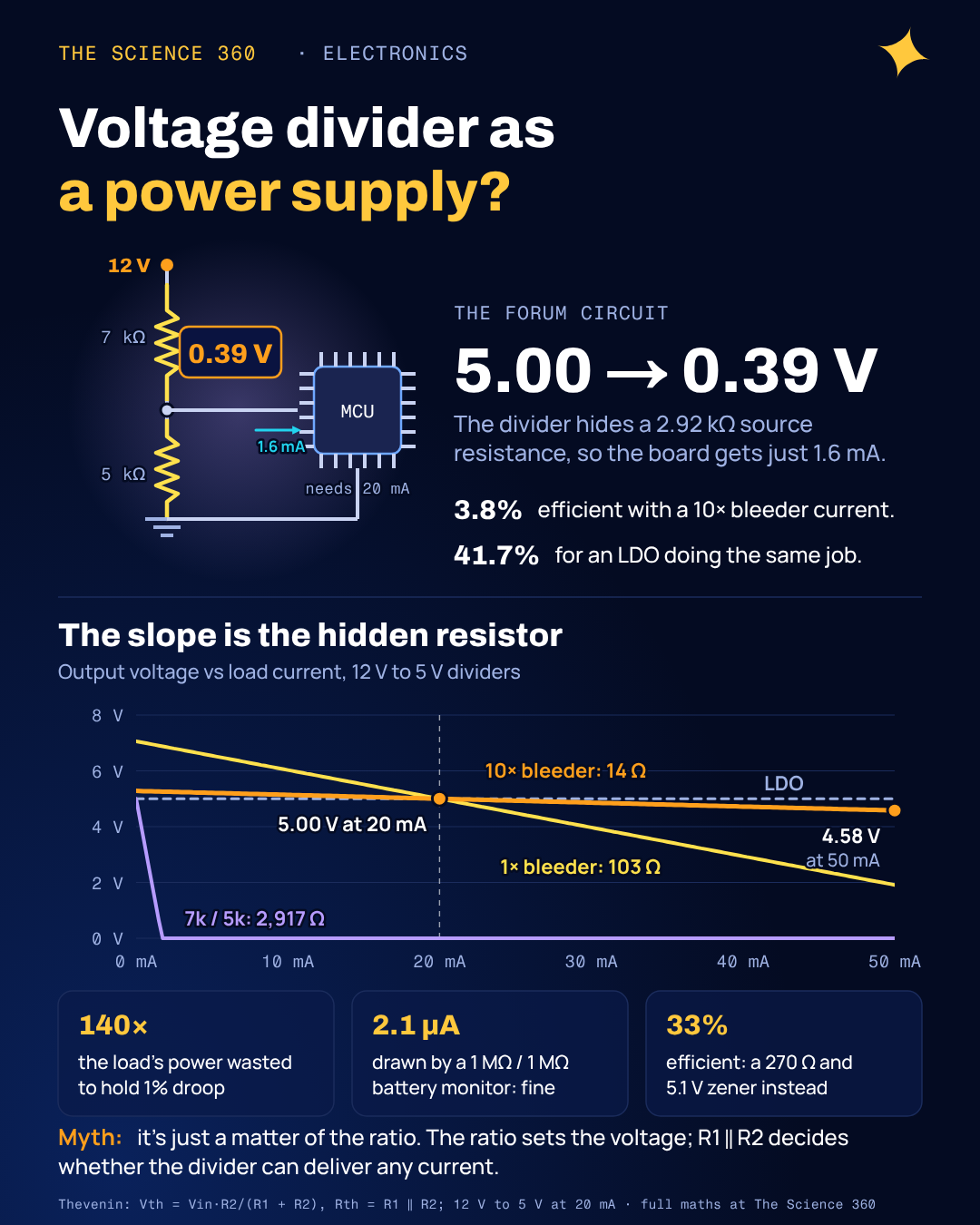
Here is a circuit that appears on electronics forums every week. You have 12 V, you need 5 V for a small board that draws 20 mA, and you remember that a 7 kΩ and a 5 kΩ resistor in series split 12 V into 7 V and 5 V. You build it, measure 5.00 V on the multimeter, connect the board, and it does nothing. The voltage at the board is now 0.39 V.
Nothing is broken. The divider did exactly what the physics says it does. The trouble is that "5 V" on an unloaded divider and "5 V supply" are different promises, and the gap between them is one resistor you did not draw. This post works out that resistor, shows the hard trade-off between regulation and efficiency that every resistive divider is stuck with, and lists the jobs where a divider is the right tool.
Why does the voltage drop when you connect a load?
The unloaded divider formula, , assumes no current leaves the middle node. Connect a load and it sits in parallel with R2, so the bottom of the divider becomes smaller and the output falls. That is correct but awkward to reason with. The cleaner way is Thevenin's theorem: from the load's point of view, any network of resistors and a voltage source looks like one voltage source with one series resistor.
Thevenin equivalent of a divider
Vth is the open-circuit voltage. Rth treats the input voltage source as a short.
Apply it to the forum circuit. A board drawing 20 mA at 5 V looks like a 250 Ω resistor.
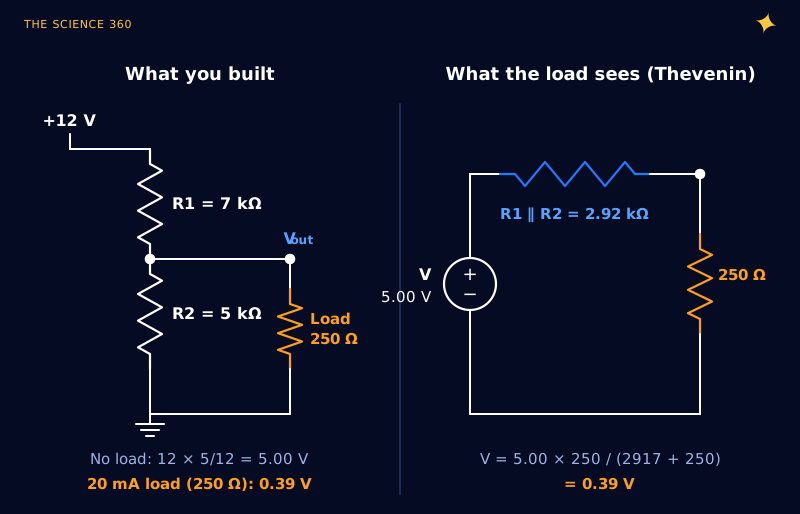
The divider is a 5 V source with 2.9 kΩ of internal resistance. For comparison, a fresh AA alkaline cell has an internal resistance of a fraction of an ohm. The divider is roughly ten thousand times "softer" than a battery.
The misconception: “it’s just a matter of the ratio”
Most beginners think of a divider as a ratio device, so any pair with the right ratio should work. 7 Ω and 5 Ω, 7 kΩ and 5 kΩ, 7 MΩ and 5 MΩ all give 5 V unloaded. The ratio sets Vth. The absolute values set Rth, and Rth is what decides whether the divider can deliver current. Choosing the ratio is half the design, and it is the easy half.
So the obvious fix is to scale the resistors down until Rth is small compared with the load. That is where the second problem arrives.
What does the “10 times bleeder current” rule actually buy you?
A common rule of thumb on forums is to let ten times the load current flow through the divider (the "bleeder" current), so the load is a small perturbation. Let us design it properly for our 12 V to 5 V, 20 mA case, so the output is exactly 5 V at full load.
Design for 5.00 V at 20 mA with bleeder current k × IL, k = 10
Power
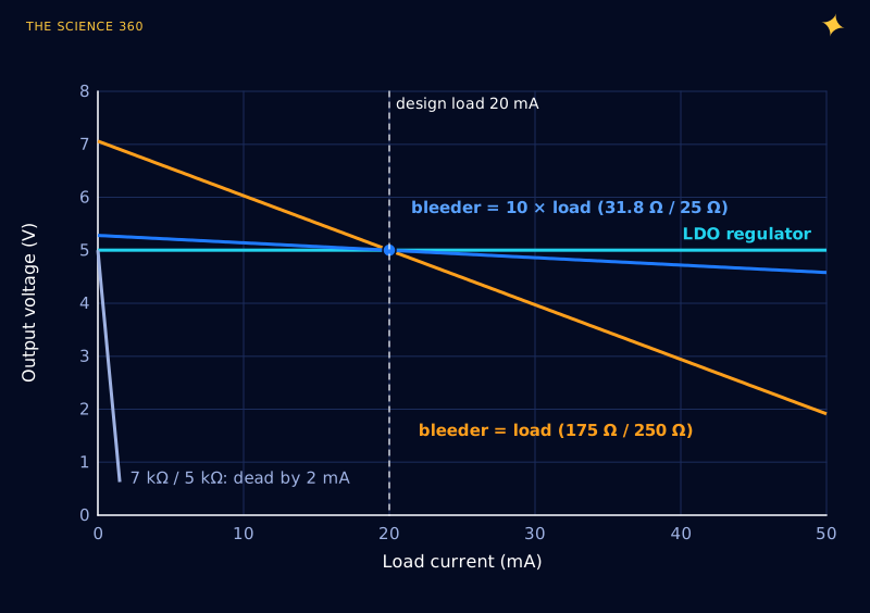
The output now moves from 5.28 V with the board unplugged to 5.00 V at full load, a 5.3% swing. In exchange, the divider burns 2.5 W of heat to deliver 0.1 W, and R1 needs to be a 2 W or 3 W part. Figure 2 shows the load behaviour of this design next to a weaker divider and a regulator.
The efficiency limit nobody mentions
Here is the part I could not find on page one of the search results, and it is the most useful result in this post. For a resistive divider designed to hit its target voltage at full load, the efficiency and the load regulation are locked together by a simple formula. Call the voltage ratio and the bleeder ratio k. Working through the algebra (R1 and R2 as above, then the no-load voltage):
Efficiency at full load, and droop from no load to full load:
Divide one by the other:
For 12 V to 5 V, . Allow 1% droop and η = 0.71%, so the divider wastes 140 times the load's power. Allow 5.3% droop and η = 3.8%, which is the 10× design above.
The bleeder ratio drops out entirely. There is no clever choice of resistors that escapes it: if you want the voltage to move by only 1% between "load off" and "load on", you will spend about 140 times the load power doing it. Figure 3 puts that line next to the alternatives.
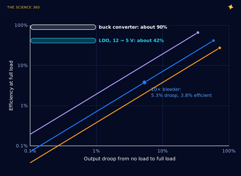
Look at where each line ends, at the top right. With no bottom resistor at all (k = 0), the divider's efficiency equals Vout/Vin, exactly what an LDO achieves. But its regulation is then total: with no load, the output floats to the full 12 V. An LDO gets the same efficiency with a fraction of a percent of droop, because it replaces R1 with a transistor whose resistance is adjusted continuously by a feedback loop.
Why changing loads make it worse
The 5.3% figure assumed a load that is either off or drawing 20 mA. Real electronics do not behave so politely. A microcontroller might draw a few microamps asleep and tens of milliamps awake, and a radio module draws short bursts far above its average. The divider output follows every one of those changes with a slope equal to Rth.
With our 14 Ω design, a load that briefly draws 50 mA pulls the output down to . A bulk capacitor across the output can smooth short bursts, but it cannot fix the average, and the time constant Rth × C sets how fast it recovers (the same exponential covered in our post on why the RC time constant is 63%).
There is also a quieter failure: the divider passes through every ripple and spike on the input in exact proportion. A regulator rejects most of it.
What should you use instead?
A linear regulator (LDO) is the direct replacement for small loads. Microchip's MCP1703A, for example, accepts up to 16 V in, delivers up to 250 mA at outputs of 2.5 V and above, and draws about 2 µA of quiescent current itself. For our 20 mA board:
The 0.14 W of heat is fine for a small package. Compare the 10× divider: 2.64 W input, 3.8% efficient, 5.3% droop.
A buck converter is the answer when the voltage ratio is large or the current is more than a few tens of milliamps. It stores energy in an inductor instead of burning the difference, and small modules are commonly 85% to 95% efficient. Our post on how a buck converter works walks through why.
A zener shunt regulator is the halfway house, and it is worth understanding because it is literally a divider with a smart bottom resistor. Replace R2 with a zener diode: when the load takes more current, the zener takes less, and the voltage barely moves.
Zener shunt, 12 V → 5.1 V, load 0 to 20 mA
Keep at least 5 mA in the zener at full load, so the series current is 25 mA:
Zener current is 25.6 mA with no load and 5.6 mA at full load. The 7 Ω is the 1N4733A's ZZT maximum at its test current; it is higher at low current. PZ is the worst-case zener dissipation, at no load.
Same circuit position as R2, about half the voltage swing of the 10× divider (0.14 V against 0.28 V) and nearly nine times the efficiency, because the wasted current is now sized to the load rather than to ten times the load. An LDO is better still, because it wastes nothing when the load is off.
When is a voltage divider perfectly fine?
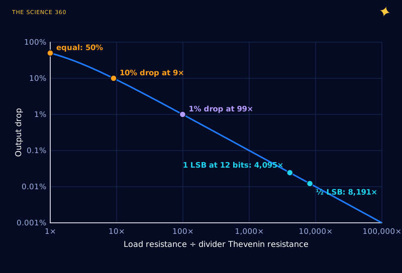
Whenever the "load" is a high-impedance input that takes almost no current. The rule is a direct consequence of the Thevenin model: the fractional error is , which Figure 4 plots.
Jobs where that condition holds easily:
- Op-amp and comparator inputs. CMOS inputs take picoamps to nanoamps. A 100 kΩ / 100 kΩ divider making a mid-supply bias point is the textbook use.
- Regulator feedback pins. Every adjustable regulator uses a divider to compare its output against an internal reference. The pin takes almost nothing, and the regulator does the heavy lifting.
- Battery monitoring with an ADC. A 1 MΩ / 1 MΩ divider across a 4.2 V lithium cell draws only 2.1 µA. The catch is dynamic, not static: Rth = 500 kΩ, so charging a 10 pF sample-and-hold capacitor to 12-bit accuracy takes 9.01 × 500 kΩ × 10 pF = 45 µs, longer than many ADCs allow. A 100 nF capacitor at the pin fixes it: the sampling capacitor then disturbs the pin by about 10 pF / 100 nF = 0.01%, roughly 0.4 LSB at 12 bits.
- Slow logic level shifting. A 1 kΩ / 2 kΩ divider turns a 5 V signal into 3.33 V for a 3.3 V input. With Rth = 667 Ω and about 10 pF of input capacitance, the time constant is under 7 ns, fine for UART and slow SPI, not for fast buses.
The common thread: in every one of these, the divider sets a voltage and something else (a high-impedance input, an op-amp, a regulator's pass transistor) supplies the current. An op-amp follower after a divider is, in effect, a tiny linear regulator. That is the right mental model for the whole topic. A divider is a reference, not a source.
FAQ
Why does the voltage drop when I connect a load to a voltage divider?
The load sits in parallel with the bottom resistor and lowers its effective value. Equivalently, the divider behaves like a source equal to its unloaded output voltage in series with R1 and R2 in parallel. Any load current flows through that series resistance and drops voltage across it.
Can I power an Arduino or microcontroller from a voltage divider?
Not sensibly. A microcontroller's current changes by a factor of a thousand between sleep and active modes, so a divider's output would swing wildly. Making the divider stiff enough wastes far more power than the chip uses. Use a linear regulator or a buck converter.
What is the 10 times rule for voltage dividers?
It says the current through the divider should be about ten times the load current. For a load that switches between zero and full current, that still gives a droop of roughly 5% from 12 V to 5 V, and the divider wastes about 25 times the power the load uses.
When is a voltage divider acceptable?
When the load draws almost no current compared with the divider's own current: op-amp and comparator inputs, ADC inputs with a capacitor at the pin, regulator feedback pins, bias points and slow logic level shifting. A rule of thumb is a load resistance at least 100 times the divider's Thevenin resistance for 1% accuracy.
Is a zener diode better than a voltage divider?
For regulation, yes: a zener shunt regulator holds its voltage within a few hundred millivolts as the load changes, because the zener adjusts its own current. It is still inefficient, because the series resistor must pass the maximum load current plus a margin at all times.
Related on The Science 360
Sources
- Wikipedia, "Voltage divider" (loading effect and Thevenin equivalent): en.wikipedia.org/wiki/Voltage_divider
- Wikipedia, "Thévenin's theorem": en.wikipedia.org/wiki/Thévenin's_theorem
- Build Electronic Circuits, voltage divider tutorial (loaded divider example and recommendation to use a regulator): build-electronic-circuits.com/?p=2467
- All About Circuits forum, "voltage divider" thread (the ten-times bleeder current rule of thumb): forum.allaboutcircuits.com/threads/voltage-divider.184099
- Microchip, MCP1703A 250 mA, 16 V low quiescent current LDO datasheet (2.7 to 16 V input, about 2 µA typical quiescent current): MCP1703 datasheet (Digi-Key HTML)
- onsemi 1N4733A, 5.1 V 1 W zener (ZZT 7 Ω maximum), distributor listing: digikey.tw/en/products/detail/onsemi/1N4733A/977210
- TI, MSP430FR267x datasheet, ADC sampling (9.01τ for 12-bit settling): ti.com document viewer
Method note: the efficiency and droop relations are my own derivation for a divider sized to give its nominal voltage at full load, with the load switching between zero and full current. All figures are computed from the Thevenin equations; the ADC sampling capacitance and logic input capacitance are round illustrative values.
Header image: NASA (image GRC-2013-C-04609), regraded for this article.