NTC Thermistor Calculation: Beta vs Steinhart-Hart
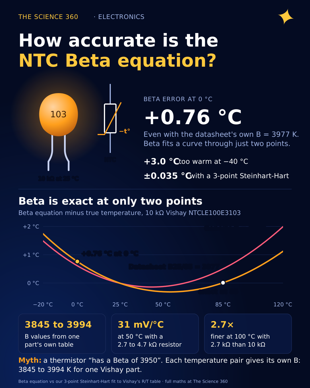
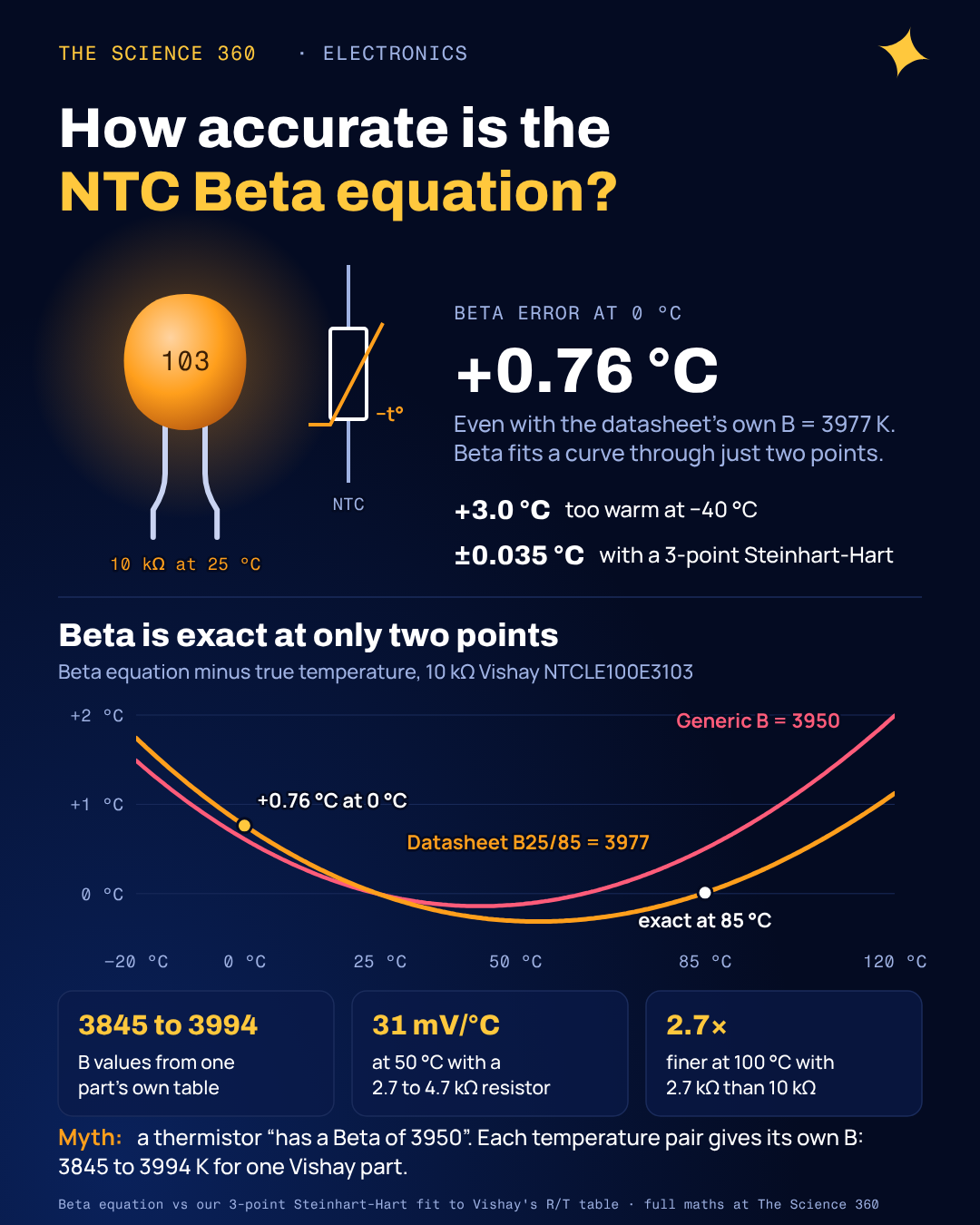
Vishay's datasheet for its 10 kΩ NTCLE100E3103 thermistor lists a Beta value of 3977 K. Plug that number into the Beta equation and read the sensor at 0 °C, and your code reports 0.76 °C. At −40 °C it reports +3.0 °C too warm. Nothing is broken: the Beta equation is a two-point straight-line fit to a curve, and 3977 K is the line through 25 °C and 85 °C. Most of the calculators that rank for this topic give you the formula, a generic "B = 3950" and a 10 kΩ pull-up, and stop there.
This post does the whole chain with real numbers from one real part: the resistance-to-temperature models and how far each is off, how to pick the fixed resistor (three different "optimal" answers, and which one you want), the ADC code to temperature conversion, and the self-heating that a wrong resistor can add.
The Beta equation and where B comes from
An NTC thermistor is a ceramic semiconductor whose resistance falls roughly exponentially with temperature. The simplest model writes that as
or, solved for temperature:
T in kelvin, T0 = 298.15 K (25 °C), R0 = R25.
B is not a material constant you can look up once. It is defined by two calibration temperatures, and the datasheet tells you which two with a subscript. Vishay specifies B25/85: the value that makes the equation exact at 25 °C and 85 °C. You can recover it from the datasheet table:
From the Vishay NTCLE100E3103 table, R25 = 10,000 Ω and R85 = 1,070 Ω:
Do the same with other pairs from the same table and you get B0/25 = 3845 K, B25/50 = 3932 K, B25/85 = 3977 K and B25/100 = 3994 K. A 4% spread from a single part. That is the first misconception to clear up: a thermistor does not "have a Beta of 3950". It has a family of Beta values, one per temperature pair, and a cheap listing that says "B3950" without a subscript is not telling you which pair it means.
The 3845, 3932 and 3994 K figures are our own calculations from Vishay's published table; Vishay itself states only B25/85.
How accurate is the Beta equation?
Vishay publishes the full resistance table for this part in 5 °C steps from −40 to 150 °C, plus an "extended Steinhart and Hart" polynomial that reproduces it to within 0.005 °C from 25 to 125 °C. That table is our reference. Figure 2 shows what each model calculates minus the true temperature, using the table resistance as the input.
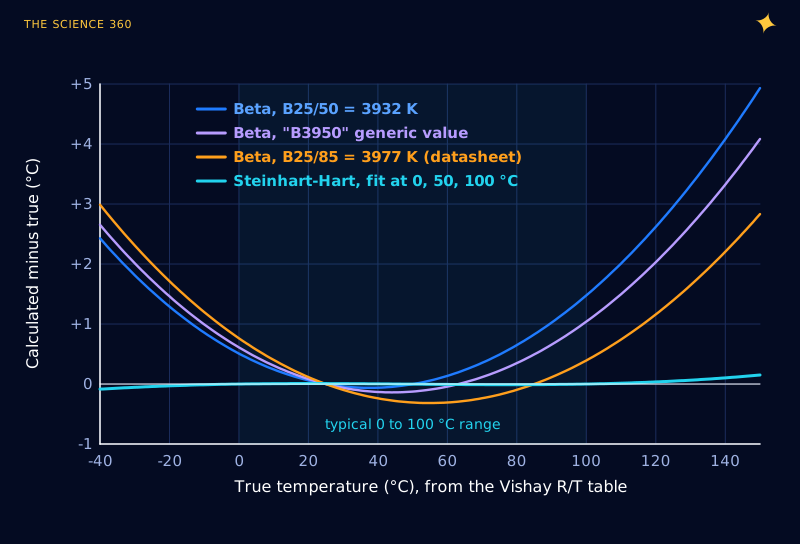
Three things stand out. With the datasheet B25/85, the Beta equation is within ±0.4 °C from about 15 to 100 °C and still 0.76 °C off at 0 °C. Using the wrong B (the generic 3950, or B25/50 when you measure up to 120 °C) moves the bowl and costs you several degrees at the hot end. And the error is systematic, not noise: averaging readings will not remove it.
Whether 0.8 °C matters depends on the part. Vishay works an example in its datasheet: a ±5% R25 tolerance plus ±0.92% from B tolerance gives ±1.17 °C at 0 °C. At 25 °C, with a temperature coefficient of −4.38%/K, a 5% part is already ±1.1 °C and a 1% part ±0.23 °C. So with an off-the-shelf 5% thermistor, the Beta equation's model error is smaller than the part tolerance over most of 0 to 100 °C. With a 1% part, or a part you calibrate, the model becomes the dominant error, and Steinhart-Hart pays off.
Steinhart-Hart: three points instead of two
Steinhart and Hart (1968) added terms in the logarithm of resistance:
Three unknowns need three calibration points. Take them from the table at the bottom, middle and top of your range, write the equation three times and solve the 3 × 3 linear system (any spreadsheet or numpy does it in one line):
Solution (our fit):
Error against the table: within ±0.035 °C from −20 to 120 °C, 0.16 °C at 150 °C.
That is roughly 20 times better than Beta over the same range, for the cost of one extra coefficient and a cube. On any microcontroller with a floating-point log, the run time difference is negligible. If you need better still, Vishay's own four-term polynomial (with a squared term as well) matches its table to 0.005 to 0.015 °C, and a lookup table with interpolation built straight from the datasheet is just as good.
Which fixed resistor gives the best reading?
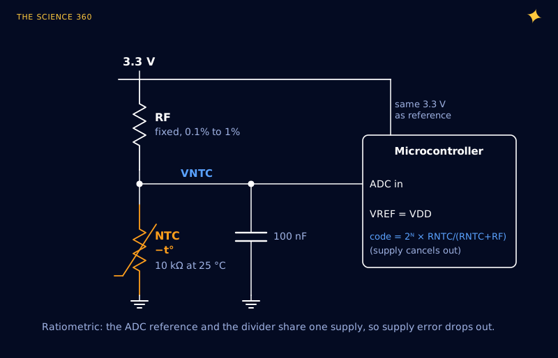
The divider in Figure 1 puts the NTC at the bottom and a fixed resistor RF at the top, so the voltage falls as temperature rises:
Slope:
The common advice is "use a fixed resistor equal to R25", so 10 kΩ for a 10 kΩ NTC. That is right only if 25 °C is the temperature you care most about. Three different design rules exist, and they answer three different questions. For a 0 to 100 °C design with our part:
| Rule | What it maximises | Formula | RF for 0 to 100 °C |
|---|---|---|---|
| Slope at one temperature | Set | ||
| Geometric mean | Total voltage swing over the range | ||
| Inflection at mid-range | Linearity around the middle |
TDK's readout application note uses the geometric-mean rule. The first rule follows from differentiating the slope with respect to RF; the third comes from setting the second derivative of V(T) to zero with the Beta model, which puts the steepest, straightest part of the S-curve at your chosen temperature. Figure 3 shows all of them alongside the 10 kΩ default.
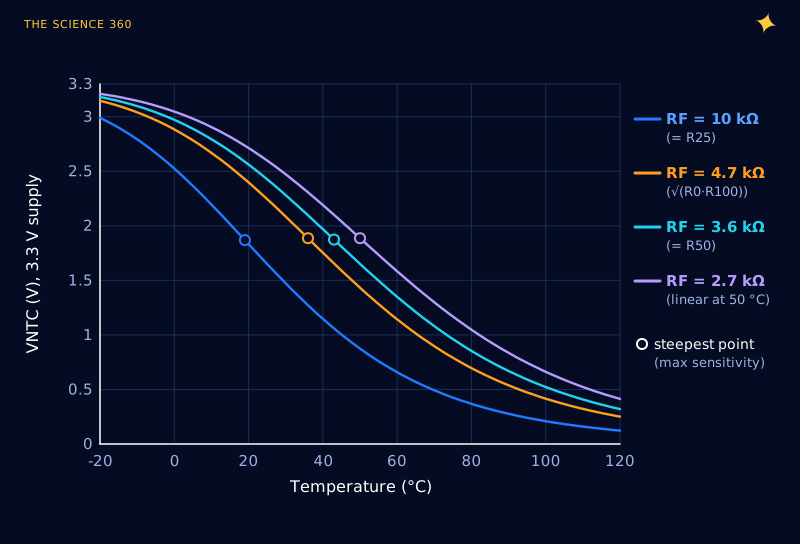
The surprise is how little the three "optimal" choices differ in the middle. At 50 °C on 3.3 V:
3.6 kΩ is the maximum, as the first rule promises.
Total swing 0 to 100 °C: 2.32 V (10 k), 2.47 V (4.7 k), 2.45 V (3.6 k), 2.39 V (2.7 k).
Anything from 2.7 to 4.7 kΩ is within 2% of the best possible slope at 50 °C. The real decision is where you want resolution to go, and that shows up at the ends of the range. The ADC sees steps of on a 12-bit converter, so temperature per count is 0.806 mV divided by the slope:
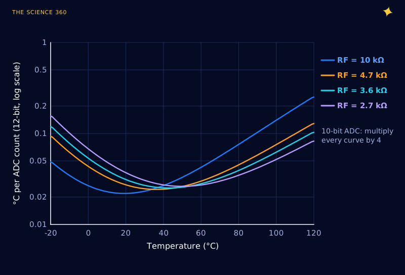
At 100 °C, 12-bit:
At 0 °C: 10 kΩ → 0.027 °C per count, 2.7 kΩ → 0.068 °C per count.
On a 10-bit Arduino every number is four times bigger. That is where the choice bites: 10 kΩ gives 0.56 °C per count at 100 °C on a 10-bit ADC, coarse enough to see as steps in a log. Remember that resolution is not accuracy; ADC offset, gain error and noise usually exceed one count, which is covered in ADC resolution vs accuracy. And use a 0.1% or 1% fixed resistor: its tolerance feeds straight into RT, and 1% of resistance is about 0.23 °C at 25 °C.
From ADC code to temperature: a worked example
Take an Arduino Uno: 10-bit ADC, 5 V supply used as the reference, RF = 10 kΩ on top, the Vishay NTC at the bottom. The ATmega328P datasheet defines the result as . Because VIN is a fraction of the same 5 V, the supply cancels out:
Reading: code = 405
Beta (B = 3977 K):
Steinhart-Hart (our fit): 34.98 °C; Vishay polynomial: 34.97 °C.
One count either side (404, 406): 34.87 and 35.07 °C, so 0.10 °C per count here.
The Beta answer is 0.18 °C low at this point, consistent with Figure 2. Two habits make this code robust. First, never use VCC in the conversion; work in ratios as above, so a 4.8 V USB supply gives the same answer as 5.0 V. Second, put a 100 nF capacitor from the ADC pin to ground. The ATmega328P datasheet says its ADC is optimised for sources of about 10 kΩ or less, and this divider's Thevenin resistance is 3.95 kΩ at 35 °C (6,543 Ω in parallel with 10 kΩ); the capacitor supplies the sampling charge anyway and filters noise (see why 100 nF is the standard capacitor). With 10 kΩ and 100 nF the RC time constant is under 1 ms, irrelevant next to a thermistor's thermal time constant of about 15 s for this leaded part.
// Uno, 10 k fixed resistor on top, NTC to ground on A0
const float RF = 10000.0;
const float A = 1.13939e-3, B = 2.32228e-4, C = 9.68046e-8;  // our 0/50/100 C fit
float readTempC() {
  long sum = 0;
  for (int i = 0; i < 16; i++) sum += analogRead(A0);
  float code = sum / 16.0;
  float r = RF * code / (1024.0-code);
  float L = log(r);
  return 1.0 / (A + B * L + C * L * L * L) -273.15;
}
Self-heating: the error your code cannot see
The divider current warms the thermistor above the thing it is measuring. The datasheet's dissipation factor δ tells you by how much: it is the power that raises the body temperature by 1 K. TDK's readout note derives the worst case, which occurs when :
3.3 V, RF = 10 kΩ, δ = 7 mW/K (Vishay leaded part):
3.3 V, RF = 2.7 kΩ, δ = 1.7 mW/K (TDK's figure for a small part):
5 V, RF = 2.7 kΩ, δ = 1.7 mW/K:
Our Uno example at 35 °C:
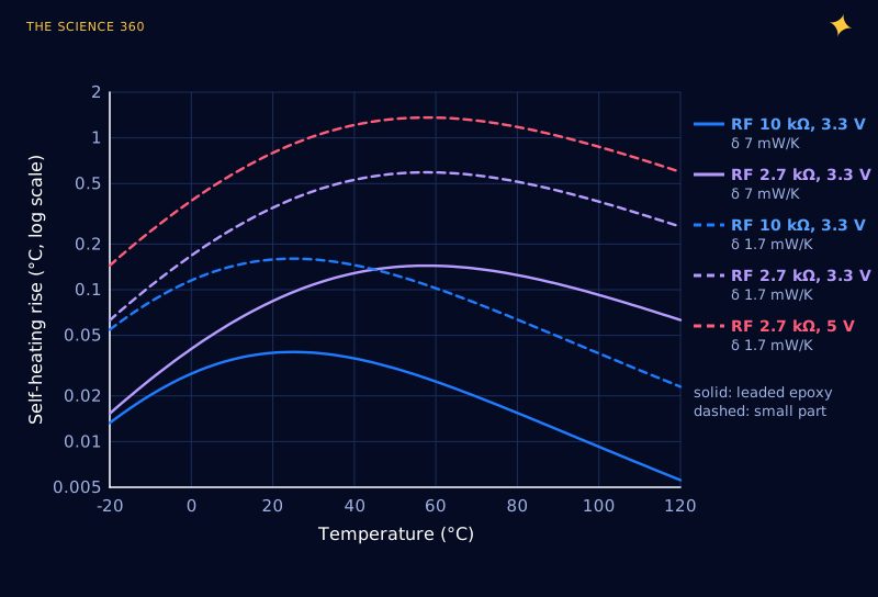
This is the trade-off nobody mentions alongside the resistor rules. Lowering RF for resolution raises the current. TDK quotes an industry rule (from IEC 60751) that self-heating should stay below 25% of the sensor tolerance; for a ±1% part that is about 0.06 °C, which the 2.7 kΩ, small-part case misses tenfold. The dissipation factor also depends on mounting: still air, a PCB pad and a stirred liquid differ by large factors, and the datasheet value is "for information only".
Three fixes, in order of preference. Power the divider from a GPIO pin and switch it on only for the few milliseconds of a reading; with a 15 s thermal time constant the average power, not the peak, sets the rise, so a 1% duty cycle cuts it a hundredfold. Use a higher-value thermistor (a 100 kΩ NTC with a 22 to 47 kΩ fixed resistor; TDK's note gets 0.1 K worst case that way on 3.3 V). Or run the divider from a lower reference voltage. The same divider analysis applies to battery packs, where the NTC pin on a charger IC is how phone charging adapts to temperature.
A design checklist
- Get the datasheet R/T table or coefficients for your exact part. If all you have is "10K B3950", treat the model error in Figure 2 as a lower bound and calibrate at two temperatures (ice water and a known warm point).
- Pick RF from your range: R at the middle temperature, or . Use 10 kΩ only for a range centred on room temperature.
- Check self-heating with , and switch the divider off between readings if it is more than a quarter of your error budget.
- Reference the ADC to the divider supply and convert with . The divider math is the same as any voltage divider, and the top resistor plays the same role as a pull-up resistor.
- Use Steinhart-Hart (three points) or a lookup table if you need better than about ±0.5 °C over a 100 °C span.
FAQ
How do you calculate temperature from NTC thermistor resistance?
With the Beta equation, , with T in kelvin, T0 = 298.15 K and R0 the resistance at 25 °C. For a 10 kΩ part with B = 3977 K, a reading of 6,543 Ω gives , so T = 307.94 K or 34.8 °C. Steinhart-Hart or the maker's table is more accurate over wide ranges.
How accurate is the Beta equation for a thermistor?
Against Vishay's table for its NTCLE100E3103, the Beta equation with the datasheet B25/85 of 3977 K is exact at 25 and 85 °C, about 0.3 °C low near 55 °C, 0.8 °C high at 0 °C and 3 °C high at −40 °C. A three-point Steinhart-Hart fit stays within 0.04 °C from −20 to 120 °C.
What resistor should I use with a 10k NTC thermistor?
Size it to the temperature range, not to the 25 °C value. For 0 to 100 °C, anything from about 2.7 to 4.7 kΩ gives about 31 mV per degree at 50 °C on 3.3 V and roughly twice the resolution of 10 kΩ at 100 °C. 10 kΩ is right only when you care most about room temperature.
What is the difference between B25/50 and B25/85?
They are Beta values calculated from the resistance at 25 °C and at 50 °C or 85 °C. Because a real thermistor does not follow the Beta equation exactly, the numbers differ: for the same Vishay part, B25/50 is 3932 K and B25/85 is 3977 K. Use the one whose temperature span matches yours.
Does thermistor self-heating matter?
It can. The worst-case rise is . On 3.3 V with 10 kΩ and a leaded part at 7 mW/K it is only 0.04 °C, but a small part at 1.7 mW/K with a 2.7 kΩ resistor on 5 V heats itself by about 1.4 °C.
Related on The Science 360
Sources
- Vishay BCcomponents, NTCLE100E3 datasheet, document 29049, rev. 07-May-2025 (R/T table for NTCLE100E3103, B25/85 = 3977 K ±0.75%, extended Steinhart-Hart coefficients and 0.005 to 0.015 °C interpolation accuracy, TCR −4.38%/K at 25 °C, tolerance example ±1.17 °C at 0 °C, dissipation factor 7 mW/K, thermal time constant 15 s): vishay.com/docs/29049/ntcle100.pdf
- TDK Electronics, "Digital Readout of NTC Thermistors: Circuit Optimization" application note, 2024 ( bias rule, self-heating , 1.7 mW/K, IEC 60751 25% rule, 100 kΩ with 22 kΩ example): tdk-electronics.tdk.com readout optimization application note PDF
- Microchip (Atmel), ATmega328P automotive datasheet, 7810D (; ADC optimised for source impedance of about 10 kΩ or less): microchip.com ATmega328P datasheet PDF
Method note: All curves are computed in Python from Vishay's published R/T polynomial for the NTCLE100E3103. The Beta curves, the Steinhart-Hart fit, the divider slopes, the ADC resolution and the self-heating curves are our own calculations.
Header image: NASA (image jsc2024e078233), regraded for this article.