Why Is the RC Time Constant 63%? The Math of 1 − 1/e

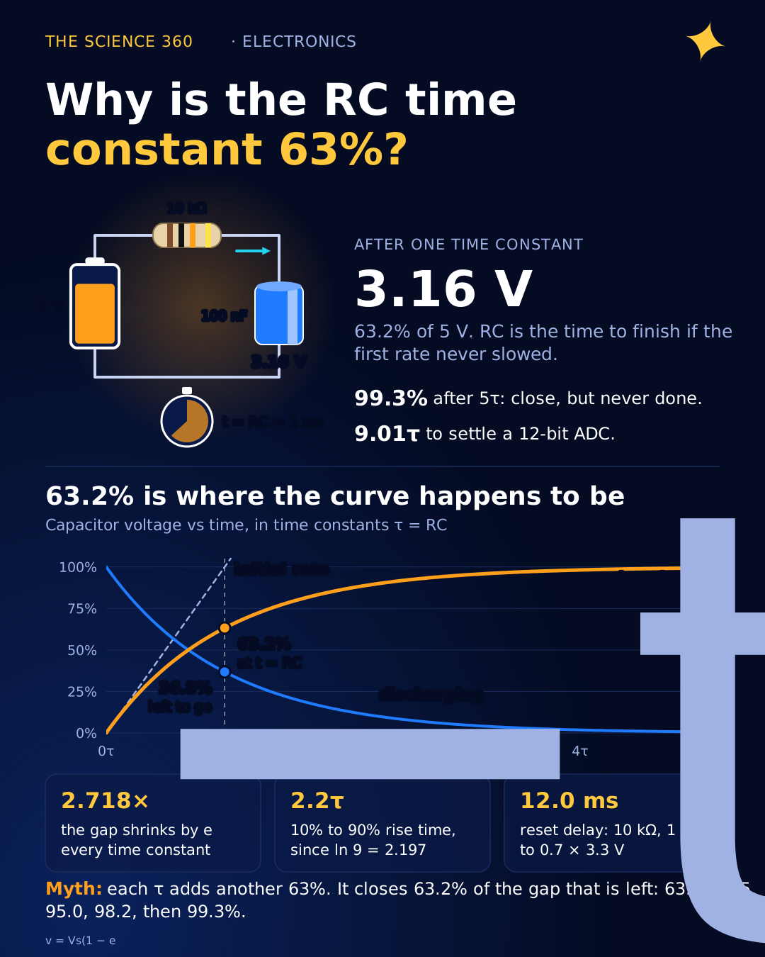
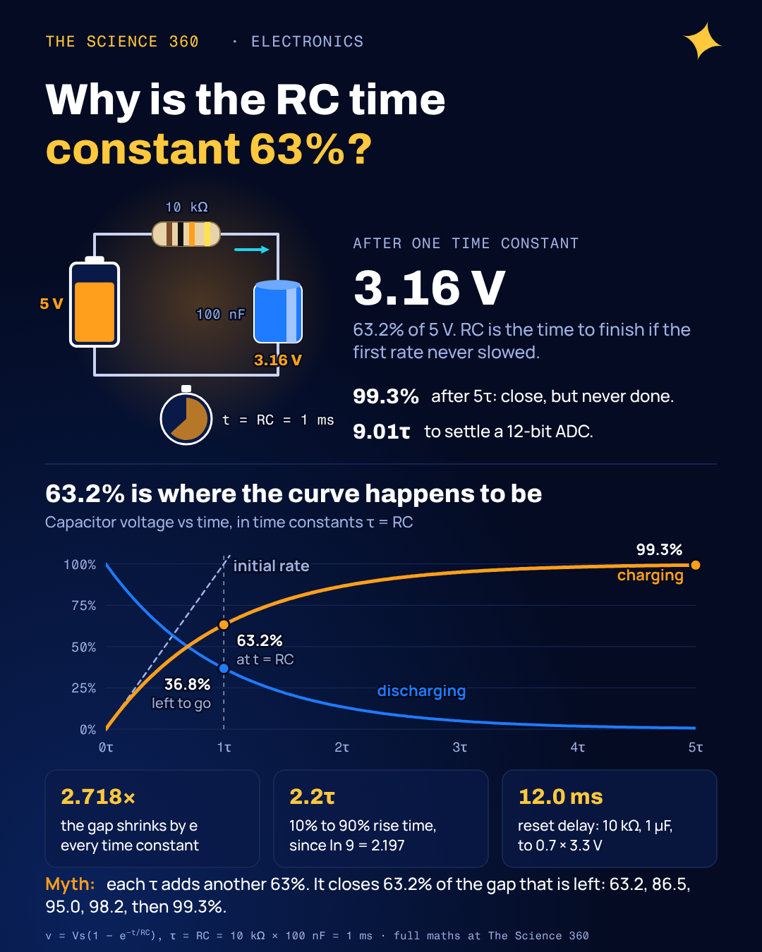
Put a 10 kΩ resistor in series with a 100 nF capacitor, connect 5 V, and start a stopwatch. After exactly 1 ms the capacitor sits at 3.16 V. Not 2.5 V, not 4 V: 3.16 V, which is 63.2% of the supply. Swap in any resistor and any capacitor and the same thing happens at t = R × C. Every textbook prints the number. Very few explain why the universe picked such an awkward one.
The short version is that nobody picked 63.2%. Engineers picked R × C because it is the only time scale the circuit has, and 63.2% is simply where the curve happens to be at that moment. Once you see why, the "5 time constants means fully charged" rule also stops looking like a law and starts looking like the rough convention it is.
Where does the RC charging equation come from?
Two facts are enough. The resistor's current is the voltage across it divided by R. The capacitor's current is C times how fast its voltage changes. In a series loop those currents are the same current, so:
Read that last line slowly, because it contains the whole story. The capacitor charges at a rate proportional to how far it still has to go. At the start the gap is the full 5 V and the voltage climbs fast. Halfway up, the gap is half as big, so the rate is half as big. The closer it gets, the slower it moves. The only function whose rate of change is proportional to itself is the exponential, so the solution is:
Notice that R and C never appear separately. Only their product matters, and it has to have units of time for the exponent to be a pure number. It does: an ohm is a volt per ampere, a farad is a coulomb per volt, so Ω × F is coulombs per ampere, which is seconds. For our parts, , or 1 ms.
Why is it 63.2 percent at one time constant?
Plug t = RC into the charging equation and the exponent becomes exactly −1:
That is the voltage after 1 ms with 10 kΩ and 100 nF.
So 63.2% is just 1 − 1/e. That answers "what", but the better question is why RC deserves to be the unit at all. Figure 1 shows the answer as geometry.
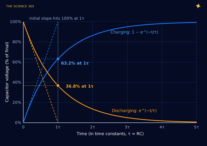
At t = 0 the full supply is across the resistor, so the current is Vs/R and the capacitor voltage rises at Vs/(RC) volts per second. If it kept that pace, it would cover the whole Vs in exactly RC seconds. That is what the time constant physically means: the time to finish if nothing slowed down. The curve does slow down, continuously, and by the time that imaginary straight line reaches the top the real curve has managed 63.2%.
Where does e come from? A step-by-step version
If the exponential feels like a trick, rebuild it by hand. Pretend the capacitor charges in jumps. Chop one time constant into n equal steps, and in each step let the voltage close 1/n of whatever gap remains at the start of that step (that is the "rate proportional to gap" rule, applied in chunks).
After one step, the gap is (1 − 1/n) of what it was. After n steps (one τ), the gap is (1 − 1/n)n.
The percentages are the charge reached. n = 1 is the straight-line fantasy.
This is the same limit that defines e in compound interest, run backwards. The finer you slice time, the more often the circuit "notices" that the gap has shrunk and eases off, and the answer converges on 1 − 1/e. There is nothing special about capacitors here. Any system whose rate of approach is proportional to its distance from the target does it: a cup of coffee cooling toward room temperature (approximately), a thermometer settling, an inductor's current in an RL circuit with , a radioactive sample decaying.
The misconception: “it charges another 63% every time constant”
A common mental slip is to think the second time constant adds another 63% of the supply, which would overshoot to 126%. What actually repeats is the fraction of the remaining gap that gets closed:
The right-hand number is how far the capacitor has charged.
Every τ, the error shrinks by the same factor of 2.718. That is why the error plot on a logarithmic axis (Figure 2) is a straight staircase, and why the curve never formally arrives.
Is a capacitor fully charged after 5 time constants?
"Five time constants and you are done" is a rule of thumb, and it is a good one for blinking LEDs, power-on delays and filter capacitors. At 5τ the voltage is within 0.67% of final, and the RC Wikipedia article states it the same way: generally considered steady state, though in theory it never arrives. The trouble starts when "done" has to mean something precise.
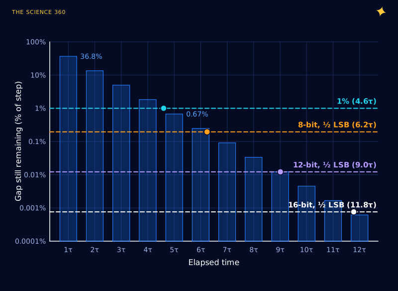
The general rule is a one-liner. To get within a fraction ε of the final value you need . For an ADC, the usual target is half a least significant bit of a full-scale step, :
Those figures are not my invention: TI's MSP430FR267x datasheet says about 9.01τ are needed for an error under ±0.5 LSB in 12-bit mode, the Xilinx XADC application note XAPP795 uses the same 9.01, and TI's analog filter settling note tabulates 11.78 for 16 bits. A design that waits 5τ before sampling a 12-bit converter can be off by 0.674% × 4096 ≈ 28 LSB on a full-scale step.
Worked example: sampling a 12-bit ADC through a source resistor. The numbers here are illustrative, not from one specific chip. Suppose a sensor with 10 kΩ output resistance drives an ADC whose sampling switch adds 1 kΩ and whose hold capacitor is 10 pF.
That is the acquisition time needed for 12 bits. If the ADC only allows 0.5 µs:
That last line is why datasheets publish a maximum source impedance, and why people put an op-amp buffer or a large capacitor right at the ADC pin. TI adds a caveat worth keeping: the full ln(2N+1) only applies to a worst-case full-scale step. If successive samples are close together the real error is smaller.
Other landmarks on the same curve
Once you can write , every other figure people quote for RC circuits is the same equation at a different threshold. Figure 3 marks the common ones.
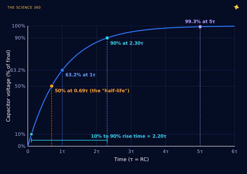
- Half-life, 0.693τ. If you prefer 50%, the circuit has a half-life just like a radioactive isotope. It is just less convenient to write than RC.
- Rise time, 2.2τ. Oscilloscope people measure 10% to 90%, which is 2.197τ. Since a first-order filter's cutoff is fc = 1/(2πτ), this gives the familiar tr ≈ 0.35/fc. Our 1 ms RC has fc = 159 Hz and tr = 2.2 ms.
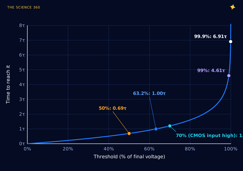
- Logic thresholds. A slow RC edge crosses a digital input's threshold at t = τ ln(Vs/(Vs − Vth)). That is how you design a reset delay or a debounce filter.
Worked example: a power-on reset delay. A 10 kΩ pull-up charges a 1 µF capacitor on a reset pin at 3.3 V. Many CMOS inputs are specified to read high above 0.7 × VDD.
Figure 4 shows why thresholds close to the rail are dangerous to design around. The time to reach 70% is 1.2τ and barely depends on the exact threshold. The time to reach 99% is 4.6τ, and a small change in where "99%" sits moves it enormously.
Why real RC timers drift from the formula
The equation assumes a perfect resistor, a perfect capacitor and an ideal supply. Three things break that in practice, and they matter more the slower the circuit.
Capacitor tolerance. General-purpose aluminium electrolytics are commonly sold at ±20% (the "M" tolerance code), so a 100 µF part can give a τ anywhere in a 1.5 to 1 range before temperature and ageing are counted. Use a C0G/NP0 ceramic or a film capacitor when timing matters.
Leakage. A real capacitor leaks DC current, which behaves roughly like a resistor RL in parallel with it. That turns the circuit into a divider: the final voltage drops to and the time constant shrinks to . Nichicon's general-purpose datasheets allow leakage up to 0.01CV or 3 µA, whichever is greater, after 2 minutes at rated voltage. For a 100 µF, 16 V part that is , which at 16 V looks like 1 MΩ. Real parts usually leak far less than that limit, but the limit is what you can design to.
Ideal: R = 1 MΩ, C = 100 µF, τ = 100 s. Crossing 3.5 V on the way down from 5 V:
With RL = 10 MΩ, Vfinal = 4.55 V and τ = 90.9 s:
With RL = 1 MΩ, Vfinal = 2.50 V, which never reaches 3.5 V.
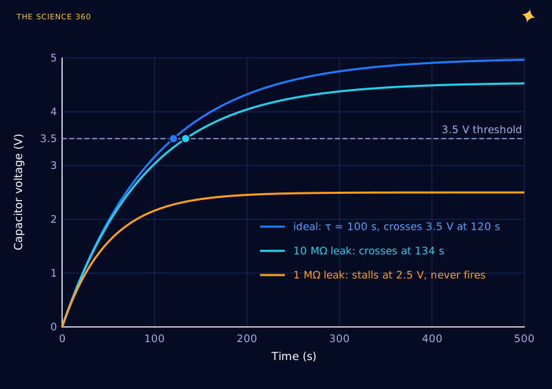
The lesson is the one Figure 4 hinted at. Keep R modest (tens to hundreds of kilohms for most timers), keep the threshold in the middle of the swing, and if you need minutes, count clock cycles instead.
Source and load resistance. Whatever drives the RC has its own output resistance, and whatever reads it loads it. Both add to or divide the R you think you have. A 10 kΩ divider feeding an RC filter adds its Thevenin resistance to the filter's R, a point the companion article on using a voltage divider as a power supply works through in detail.
FAQ
Why is the time constant 63.2 percent and not 50 percent?
Because the time constant is defined as R times C, which is the number that falls straight out of the circuit equation. At the remaining gap is , so the capacitor has covered 63.2%. The 50% point exists too: it is 0.693 RC, the RC circuit's half-life.
Is a capacitor fully charged after 5 time constants?
It is at 99.3%, which is close enough for most timing and power work. It is not enough for precision measurement: settling a 12-bit ADC input to half an LSB takes about 9 time constants, and 16 bits takes about 11.8.
What percentage does a capacitor discharge to in one time constant?
It falls to 36.8% of its starting voltage, which is 1/e. After two time constants it is at 13.5%, after three at 5.0% and after five at 0.67%.
Why are ohms times farads equal to seconds?
An ohm is a volt per ampere and a farad is a coulomb per volt. Multiply them and the volts cancel, leaving coulombs per ampere. An ampere is a coulomb per second, so coulombs per ampere is seconds.
How is the RC time constant related to cutoff frequency?
For a first-order RC filter the cutoff frequency is . A 1 ms time constant gives 159 Hz. The 10% to 90% rise time is 2.2 RC, or about 0.35 divided by the cutoff frequency.
Related on The Science 360
Sources
- Wikipedia, "RC time constant" (63.2% at 1τ, 99.3% at 5τ, rise time ≈ 2.2τ, fc = 1/(2πτ)): en.wikipedia.org/wiki/RC_time_constant
- Texas Instruments, MSP430FR267x datasheet, ADC sample timing (about 9.01τ for < ±0.5 LSB in 12-bit mode): ti.com document viewer, MSP430FR2672/3/5/6
- Texas Instruments, SBAA535, analog filter settling for ADCs (time constants to ½ LSB = ln(2N+1), 11.78 for 16 bits): ti.com/document-viewer/lit/html/SBAA535
- Xilinx, XAPP795, "Driving the Xilinx Analog-to-Digital Converter" (12 bits requires 9.01 time constants): physics.umd.edu mirror of XAPP795
- Nichicon, aluminium electrolytic capacitor datasheet, USV series (leakage current ≤ 0.01CV or 3 µA after 2 minutes at 20 °C): Nichicon USV datasheet (LCSC mirror)
- Physics Forums discussion, "Time constant: why τ = RC and 63%?" (the initial-slope interpretation): physicsforums.com/threads/time-constant-why-tau-rc-and-63.188582
Method note: all curves are computed directly from v = Vs(1 − e−t/τ). The ADC and leakage examples use round illustrative component values; check your own part's datasheet for its sampling capacitance, switch resistance and leakage limit.
Header image: NASA (image iss067e141213), regraded for this article.