How to Calculate Crystal Load Capacitors (With Stray C)

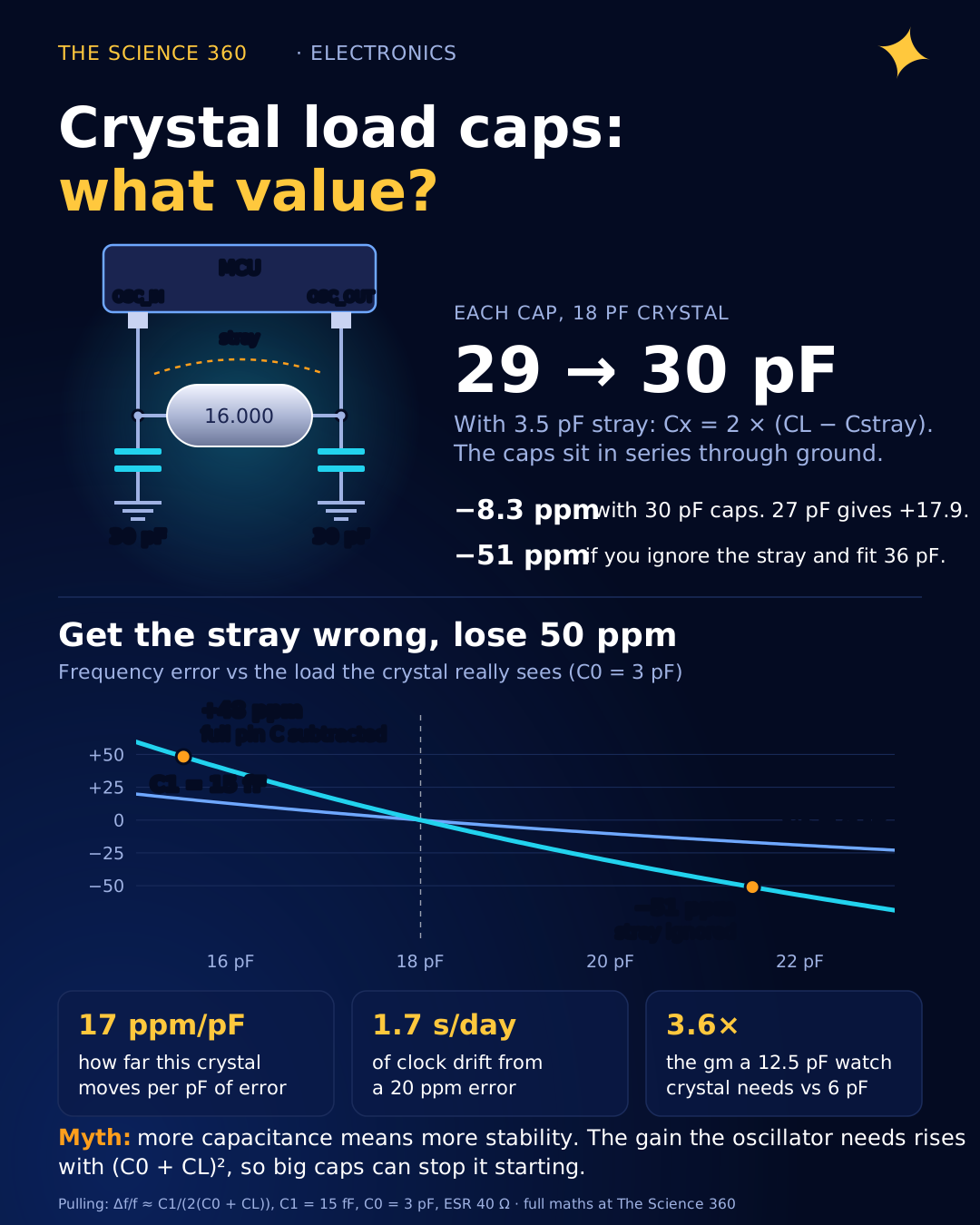
A 20 ppm frequency error sounds tiny. On a real-time clock it is 1.7 seconds a day, or close to a minute a month, which is exactly the kind of drift that makes a product reviewer write "the clock is useless". The usual cause is not a bad crystal. It is a pair of load capacitors chosen with the right formula and the wrong idea of what "stray capacitance" means.
Every guide gives the same equation. Few of them say which stray capacitance goes into it, how many ppm a mistake costs, or that choosing the capacitors also decides whether the oscillator starts at all. We will do all three with real numbers.
What does load capacitance actually mean?
A quartz crystal is a mechanical resonator with an electrical model: a series branch of motional inductance L1, motional capacitance C1 and resistance R1 (the ESR), all shunted by C0, the capacitance of the electrodes and package. On its own it has a series resonance. In a microcontroller's Pierce oscillator it runs slightly above that, at a frequency set by how much capacitance the circuit hangs across it.
The manufacturer trims each crystal so it hits its nominal frequency when it sees one particular capacitance: the load capacitance CL on the datasheet, commonly 6, 7, 9 or 12.5 pF for 32.768 kHz watch crystals and 8 to 20 pF for MHz crystals. Your job is to build a circuit that presents exactly that capacitance. Give it more and the crystal runs slow. Give it less and it runs fast.
The crystal load capacitor formula
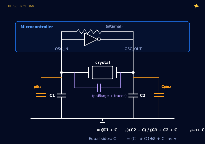
From the crystal's two terminals, C1 and C2 are in series through ground, so they combine like resistors in parallel. Anything directly across the crystal adds on top:
Equal capacitors (C1 = C2 = CX):
ST's worked example for an STM32 is the cleanest check: an 8 pF crystal with 3 pF of stray gives capacitors, and that is what they fit. NXP forum guidance uses the same formula with a stray of 2 to 5 pF.
The misconception: which “stray capacitance”?
Here is where forum threads go in circles. One person writes , another writes , and both are right, because they mean different things by Cstray.
- Per-pin capacitance (pin to ground) sits in parallel with C1 or C2. It enters the formula at half weight, because it is on one side of the series pair.
- Shunt capacitance (directly across the crystal, between the two traces and inside the package) enters at full weight.
Write the formula honestly with both and the confusion disappears:
With equal sides:
Effective stray for the simple formula:
So is the same equation with Cstray meaning the per-pin parasitic and the shunt ignored. The real error is mixing them: reading "pin capacitance 5 pF" in a microcontroller datasheet and subtracting it as if it were across the crystal, which double-counts it. ST notes that datasheets often list the I/O pin capacitance as 5 pF as a worst-case typical figure, and that experience puts the effective stray between 2 and 3 pF. Those two statements agree once you halve the per-pin number.
Worked example: a 16 MHz crystal rated for 18 pF
The crystal parameters below are illustrative values typical of an HC-49/SMD-sized 16 MHz part: CL = 18 pF, C0 = 3 pF, motional capacitance C1 = 15 fF, ESR 40 Ω maximum. Small 3.2 × 2.5 mm crystals often have a motional capacitance of only a few fF, which we will also look at.
Step 1. Estimate the parasitics
The 5 pF is the MCU pin figure from the datasheet, the 1 pF is a short trace (per side), and the 0.5 pF shunt is an estimate for two adjacent traces.
Step 2. Solve for the capacitor
Nearest E24 values: 27 pF or 30 pF.
Step 3. Check what you actually get
Which one is closer in frequency? For that we need the pulling equation.
How many ppm does a load capacitance error cost?
The crystal's operating frequency above series resonance depends on the total capacitance it sees. The standard approximation, used in ECS's crystal design notes and Raltron's primer, is:
S is in ppm per pF, with C1 in pF. For our crystal at 18 pF:
Error with 30 pF caps (18.5 pF) and 27 pF caps (17.0 pF):
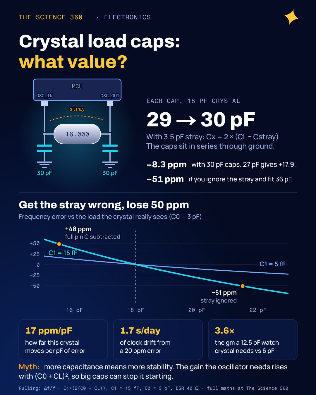
So 30 pF wins, and lands within 10 ppm of nominal before the crystal's own tolerance is counted. ECS's own example (C1 = 20 fF, C0 = 4.5 pF, CL = 30 pF) gives 8.4 ppm/pF by the same formula, a useful sanity check on the arithmetic. Now look at the two mistakes from the previous section:
Ignore stray and fit 2 × 18 = 36 pF:
Subtract the full 6 pF pin capacitance as stray and fit 2 × (18 − 6) = 24 pF:
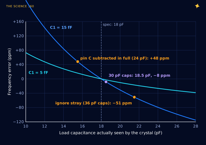
Fifty ppm is 4.3 seconds a day on a clock. It can also break a communications link. Ethernet, for instance, requires each end's clock to be within ±100 ppm, and a Bluetooth Low Energy radio's main clock must hold ±50 ppm, so a crystal that eats 50 ppm on layout mistakes plus 20 ppm of factory tolerance plus temperature drift is in trouble. A UART, by contrast, tolerates a couple of percent, so a sloppy crystal there costs nothing.
Why low load capacitance crystals are touchier
The sensitivity formula has (C0 + CL)2 in the denominator. Halve the load capacitance and the crystal becomes roughly three to four times more sensitive to every picofarad of layout error.
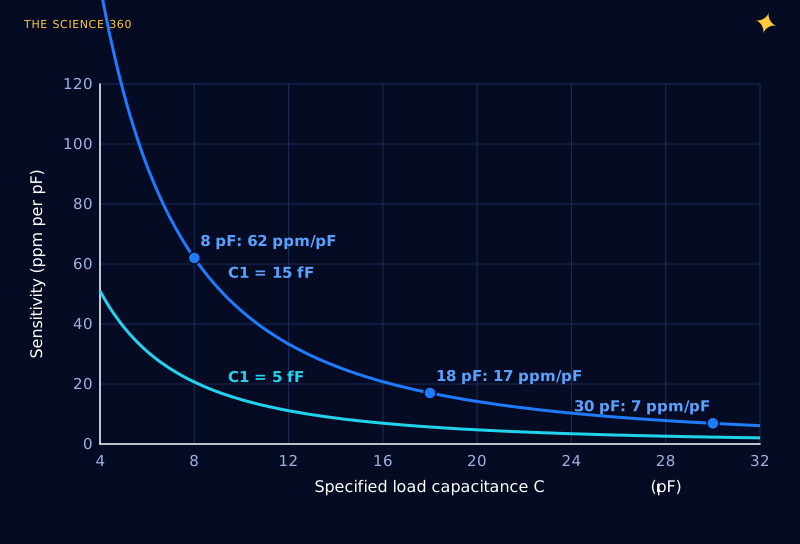
That explains the old habit of specifying 20 to 30 pF crystals: they were forgiving. Modern designs push CL down to 8 pF and below for two reasons, lower oscillator power and faster start-up, and they pay for it in sensitivity. With a low-CL crystal, measure the frequency on your first board and trim the capacitors. ST recommends exactly that for the 32.768 kHz LSE oscillator: tune empirically by measuring the RTC output.
Will the oscillator start? The gain margin check
Most load capacitor guides stop at frequency. But the same capacitors set how hard the amplifier has to work. A Pierce oscillator starts only if the amplifier's transconductance gm comfortably exceeds the critical value needed to overcome the crystal's losses. ST's application note AN2867 gives:
The (C0 + CL)2 term means bigger load capacitors make the oscillator harder to start. "Add more capacitance for stability" is a myth that can produce a board that starts at room temperature and fails in the cold, when ESR rises.
Our 16 MHz crystal
It needs an oscillator with .
Cross-check against an ST forum example (8 MHz, ESR 80 Ω, C0 3 pF, CL 20 pF):
ST's moderator quotes about 0.42.
Typical MHz oscillator cells have plenty of margin. The squeeze comes at 32.768 kHz, where the oscillator is deliberately starved of current to save battery and the crystal ESR is tens of kilohms.
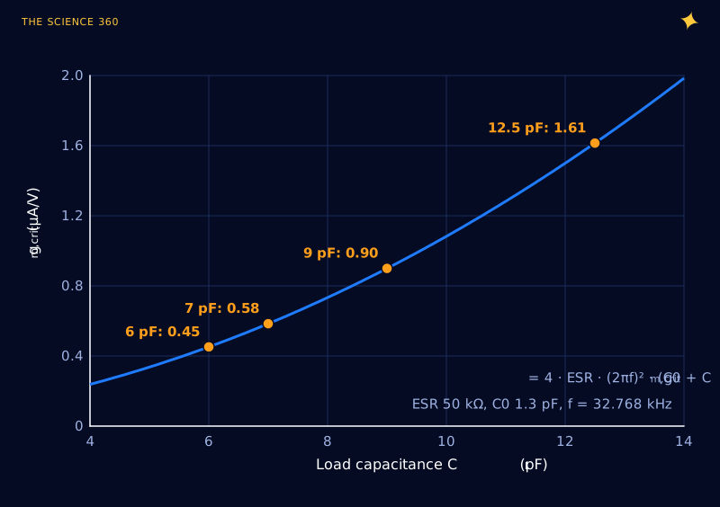
This is why 6 pF and 7 pF watch crystals exist. Low-power RTC oscillators in modern microcontrollers often specify a maximum gm,crit of only around a microamp per volt or less at their lowest drive setting. Drop a 12.5 pF crystal into such a design and the gain margin can fall below 1: the clock simply never starts. Always compare the crystal against the MCU datasheet's gm,crit,max before you look at capacitor values.
A practical procedure
- Pick the crystal against the oscillator, not the other way round. Compute gm,crit from the crystal's maximum ESR, C0 and CL, and confirm the gain margin is at least 5.
- Estimate parasitics honestly. Per-pin: the MCU's pin capacitance plus about 1 pF for a short trace. Shunt: under 1 pF for a tight layout. Effective stray = Cpin/2 + Cshunt, typically 2 to 5 pF.
- Compute CX = 2(CL − Cstray), then check both neighbouring standard values with the pulling formula and keep the closer one. Use C0G/NP0 capacitors, never X7R, whose capacitance moves with temperature and voltage.
- Keep the layout tight. Crystal and capacitors right next to the pins, a ground under them, no fast signals nearby. Every millimetre of trace is a fraction of a picofarad and an antenna.
- Measure on the prototype. Probing the crystal pins with a scope adds 10 pF or so and shifts the frequency you are trying to measure. Instead, route the clock to an output pin (MCO, CLKOUT) and use a frequency counter. Adjust CX and re-measure.
- Optionally test start-up margin. A common method is to add a resistor in series with the crystal and increase it until the oscillator fails to start; crystal makers usually recommend that this negative resistance be several times the ESR, often quoted as at least five.
FAQ
What is the formula for crystal load capacitors?
, where CL is the load capacitance on the crystal datasheet, C1 and C2 are the capacitors from each crystal pin to ground, and Cstray is the effective stray capacitance across the crystal. With equal capacitors, .
What value should I use for stray capacitance?
Start with 2 to 5 pF of effective stray capacitance for a compact layout. ST's guidance is that experience puts it between 2 and 3 pF; other sources suggest 3 to 5 pF. Then measure the actual frequency on a prototype and adjust the capacitors.
What happens if crystal load capacitors are wrong?
Too much capacitance lowers the frequency, too little raises it. For a typical 18 pF crystal, a 3.5 pF error shifts the frequency by roughly 20 to 60 ppm depending on its motional capacitance. Far too much capacitance can also stop the oscillator from starting, because the required amplifier gain rises with the square of the total capacitance.
Is the load capacitance the value of each capacitor?
No. The two capacitors are effectively in series across the crystal, so each one must be roughly twice the load capacitance, minus an allowance for stray capacitance. A crystal specified for 18 pF typically needs capacitors of about 27 to 30 pF.
Why do 32.768 kHz crystals come in 6 pF and 7 pF versions?
Lower load capacitance reduces the transconductance the oscillator needs, which lets low-power real-time clock oscillators run on less current. The cost is higher pulling sensitivity, so stray capacitance matters more.
Related on The Science 360
Sources
- ST Community knowledge article, "How to select a compatible crystal and load capacitors for STM32" (stray 2 to 3 pF by experience, pin capacitance often listed as 5 pF, 8 pF crystal with 3 pF stray gives 10 pF capacitors, empirical LSE tuning): community.st.com
- ST Community, "Oscillator design: where are ESR and gmcrit formulas from?" (AN2867 gm,crit formula, gain margin above 5, 8 MHz worked example): community.st.com
- STMicroelectronics, AN2867 "Guidelines for oscillator design on STM8AF/AL/S and STM32 MCUs/MPUs": st.com AN2867 PDF
- NXP Community, "How to calculate the value of crystal load capacitors?" (formula, stray 2 to 5 pF): community.nxp.com/thread/388856
- ECS Inc., "Quartz Crystal Design Parameters" (pulling sensitivity formula, worked example 8.4 ppm/pF): ECS design parameters PDF (MSU mirror)
- Raltron, "Crystal Mini Primer Part 1" (trim sensitivity derivation): raltron.com
- Abracon ABS07-LR 32.768 kHz crystal datasheet (6 pF load, 50 kΩ maximum ESR, 1.3 pF shunt capacitance): ABS07-LR datasheet
- All About Circuits forum, "Crystal load capacitors calculation" (the 2CL − Cstray variant): forum.allaboutcircuits.com
- TechOverflow, computing crystal load capacitors (starting estimate of 3 pF stray): techoverflow.net
Method note: the 16 MHz crystal's C0, C1 and ESR are illustrative values, not from one specific part; check your crystal's datasheet. Pulling figures use the first-order approximation Δf/f ≈ C1/(2(C0 + CL)), which is accurate to a few percent for these values. The Ethernet and BLE tolerance figures and the low-power RTC gm,crit range are from general knowledge of the standards and datasheets, not checked for this article.
Header image: NASA (image iss072e097465), regraded for this article.