LC Resonant Frequency Formula: Derivation, Q and Real Parts
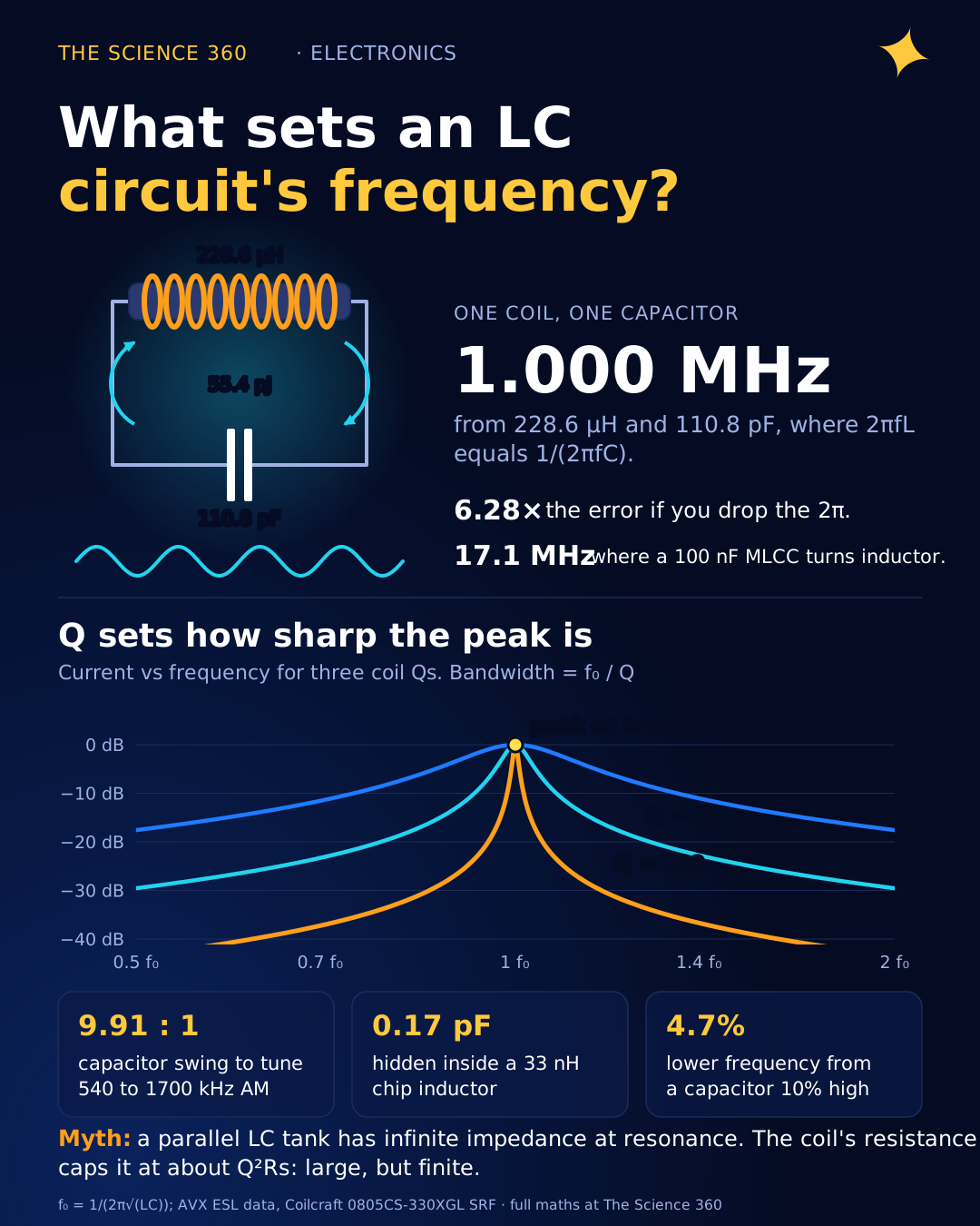
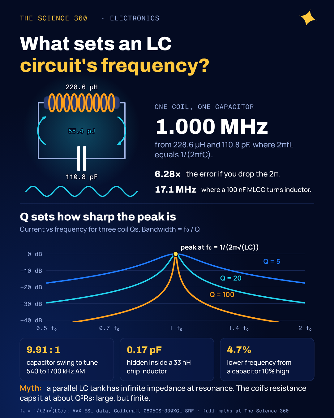
A 228.6 µH coil and a 110.8 pF capacitor, wired together and given one nudge of charge, will swap 55 picojoules back and forth between them a million times a second. That is the whole of LC resonance, and the formula that predicts the million, , is in every textbook and every online calculator. What the calculators do not tell you is how far a real circuit drifts from it, which version of "resonant frequency" you are actually measuring, and why the capacitor on your bench stops being a capacitor somewhere around 17 MHz.
Where does f = 1/(2π√(LC)) come from?
The reactance route is the one most pages use. An inductor's reactance rises with frequency, ; a capacitor's falls, . In series they subtract, because one voltage leads the current by 90° and the other lags by 90°. Resonance is where they are equal:
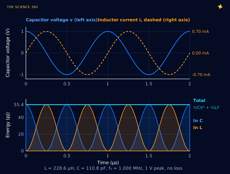
The energy route explains why the circuit wants to oscillate at all. Charge a capacitor and connect it across an inductor. Current builds gradually, because the inductor resists any change in current, while the capacitor drains. At zero volts all the energy sits in the magnetic field and the current peaks. The inductor then refuses to let that current stop, so it charges the capacitor the other way round, and the whole thing runs backwards.
Write it as two equations. The inductor says ; the capacitor says . Combine them and you get , the equation of a mass on a spring, whose solution is a cosine at . The inductance plays the role of mass (inertia against changing current) and 1/C plays the role of spring stiffness. Bigger L or bigger C, slower oscillation, and only as the square root.
The energy check is a good way to remember the peak current. At the moment all energy is in the capacitor it is ; a quarter cycle later it is all . Set them equal and . The quantity has units of ohms and is called the characteristic impedance Z0 of the resonator. You will meet it again in why coax is 50 Ω, where a transmission line's Z0 is √(L/C) per unit length.
Worked example: the energy picture at 1 MHz, with L = 228.6 µH, C = 110.8 pF, V0 = 1 V.
The 2π mistake that costs a factor of 6.28
The single most common error with this formula is mixing up f and ω. gives angular frequency in radians per second. For the example above, , and if you read that as hertz you will build a filter tuned to 6.28 MHz instead of 1 MHz. Simulators report hertz, textbooks often derive in ω, and spreadsheet formulas copied from one into the other are where the factor sneaks in. If your answer is off by 6.28, this is why.
The second common slip is units. Picofarads and microhenries are the natural units for radio work, and their product carries a 10−18. A handy shortcut for exactly those units: . Check: .
Series vs parallel LC: what is different?
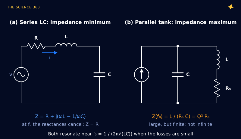
The series circuit is an impedance minimum. At f0 the inductor's and capacitor's voltages are equal and opposite, so they cancel, and the source sees only R. The parallel circuit is the dual: at f0 the currents in the two branches are equal and opposite, so the source has to supply only the small current that makes up for losses, and the tank looks like a large resistance.
Both hide a large circulating current or voltage. In a series circuit at resonance the voltage across C is Q times the source voltage, so a Q = 100 circuit driven with 1 V puts 100 V on the capacitor. That is how a wireless charging coil builds a strong magnetic field from a modest supply, and it is also how people blow up 50 V capacitors in circuits fed from 5 V.
The misconception: “at resonance a parallel LC has infinite impedance, and all resonant frequencies are the same”
Most top-ranking pages state the formula, show XL = XC, and stop; forum answers often add that a parallel tank has infinite impedance at resonance. Both hold only for perfect parts. Give the coil resistance and two things change.
First, the impedance is finite. For a coil with series resistance Rs, the tank impedance at resonance is very close to , which is the same as , where is the coil's quality factor. Electronics Tutorials gets this right in its parallel resonance page; many shorter answers do not.
Tank impedance at 1 MHz (our numbers, assuming a coil Q of 100):
The last line is a check.
Second, "resonant frequency" stops being one number. With a lossy coil in the tank, there are three reasonable definitions, and they no longer coincide:
- The undamped frequency, , which is the formula.
- The zero-phase frequency, where the tank looks purely resistive and the source current is in phase with the voltage: ω = ω0√(1 − 1/Q2).
- The frequency of maximum impedance, which stays within a hair of ω0 (the exact expression is ω0√(−1/Q2 + √(1 + 2/Q2))).
A fourth number appears if you ring the tank and watch it decay on a scope: the damped natural frequency, . Here they are for a deliberately poor coil and a good one:
Coil Q = 5, relative to :
Those are 2.0%, 0.04% and 0.5% low. At coil Q = 100, zero phase is at 0.99995 f0 (0.005% low) and ringing at 0.999988 f0.
We checked the Q = 5 numbers by brute force, sweeping the impedance of in parallel with on a fine grid: the peak lands at 0.99962 and the phase crosses zero at 0.97980. So the practical rule is simple. Above a Q of about 20 every definition agrees with to better than 0.13%, far inside component tolerance, and you can forget the distinction. Below about 10, which is common for ferrite-cored power inductors, lossy wireless charging coils and heavily loaded tanks, it matters: an oscillator that locks to zero phase will run measurably below the formula.
Q and bandwidth: how sharp is the resonance?
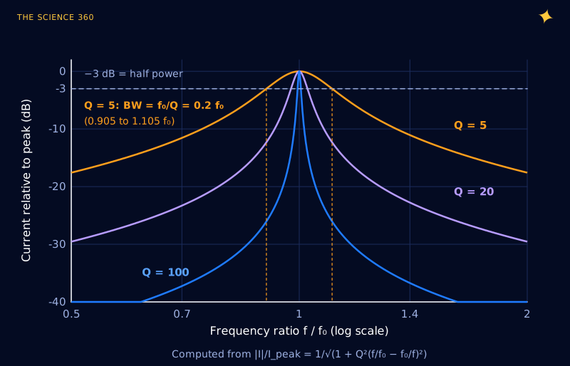
Q measures how many cycles the circuit rings before the energy leaks away. More usefully for design, it sets the bandwidth. The half-power bandwidth, measured between the two frequencies where the response is 3 dB down, is:
The bandwidth is independent of C.
That last line is worth staring at. For a series circuit with a fixed resistance, the bandwidth in hertz depends only on R and L. Retuning with the capacitor moves the centre frequency but leaves the width alone, so Q rises in proportion to frequency. The 3 dB points are not symmetric around f0 on a linear axis; they are symmetric on a log axis, with their geometric mean equal to f0. Figure 3 shows the shape for three values of Q. The same half-power definition sets the cutoff of a first-order filter, which is covered in the RC low-pass filter cutoff frequency.
Worked example: designing an AM radio tuner
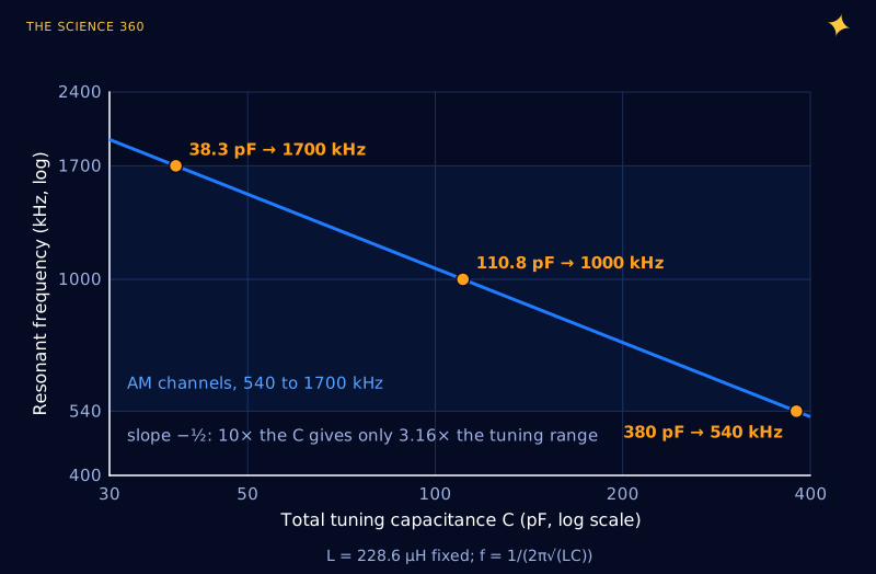
The North American AM broadcast band runs from 535 to 1705 kHz, and its 117 carrier frequencies sit on a 10 kHz grid from 540 to 1700 kHz (FCC rule 47 CFR 73.14). A single variable capacitor and a fixed coil have to cover that range. Because f depends on , the capacitance range has to be the square of the frequency range:
Pick the maximum total capacitance: Cmax = 380 pF (our choice, tuning capacitor plus strays).
Mid-band check: 1000 kHz needs 110.8 pF.
The awkward number is Cmin. The 38.3 pF is the total: the variable capacitor at its minimum setting plus every stray picofarad from the wiring, the coil's own capacitance and the next stage's input. If strays add 20 pF, the variable capacitor must swing from 18.3 to 360 pF, a ratio near 20:1, which is much harder to make than 10:1. This is why stray capacitance, a nuisance at most frequencies, is a design input for a tuner, and why the same thinking appears in choosing crystal load capacitors, where a few picofarads of board stray decide whether a crystal runs on frequency.
Now the selectivity. Suppose the coil's loss behaves like a fixed series resistance chosen to give Q = 100 at 1 MHz, which is R = 14.36 Ω. Then:
The bandwidth is the same at every setting.
A 10 kHz bandwidth on a 10 kHz channel grid sounds tidy, but a single tuned circuit is a poor channel filter. Look at Figure 3: one channel away (10 kHz off at 1 MHz, which is f/f0 = 1.01), a Q = 100 circuit is only about 7 dB down: . A strong local station next door comes straight through. Real coils also do not behave like a fixed resistor; their losses rise with frequency (partly the skin effect in the winding), so the bandwidth varies across the band. This is the reason almost every AM receiver is a superheterodyne: the antenna tank only does rough preselection, and the channel is picked by fixed-frequency filters that do not have to tune.
Why real inductors and capacitors self-resonate
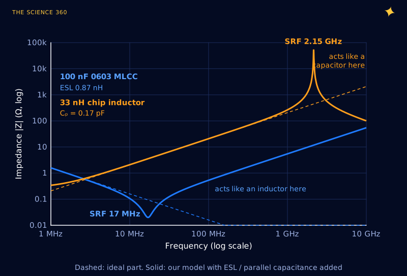
Every real capacitor has some inductance, from the current loop through its plates and terminals. Every real inductor has some capacitance, between adjacent turns. So each part is secretly an LC circuit, with a self-resonant frequency (SRF) of its own. Above that frequency the part does the opposite of its job.
Jeffrey Cain at AVX measured the parasitic inductance of 0.1 µF ceramic capacitors and found about 870 pH for an 0603 chip, 1,050 pH for 0805 and 1,200 pH for 1206. Feed the 0603 number into the formula:
100 nF 0603 MLCC, ESL = 0.87 nH:
Above 17 MHz that "capacitor" is an inductor of about 0.87 nH plus whatever the board adds, which is exactly the story told in why 100 nF is the standard decoupling capacitor. Going the other way, Coilcraft's 0805CS-330XGL, a 33 nH ceramic chip inductor, is listed with an SRF of 2.15 GHz. Invert the formula to find its hidden capacitance:
A sixth of a picofarad. That is the whole gap between a 33 nH inductor and an open circuit at 2.15 GHz, and it is why an RF designer picks an inductor whose SRF sits well above the operating frequency, often by a factor of two or more, since the effective inductance climbs steeply as you approach SRF.
How accurate does the formula need to be?
Because f0 goes as the inverse square root, tolerances are halved: a capacitor 10% high moves f0 4.7% low (). That is fine for a filter, but not for a radio that must land within 1% on a 10 kHz grid at 1 MHz, which is why tuners have trimmers and why fixed-frequency oscillators use a quartz crystal, a mechanical resonator with a far higher Q than any coil (see why watch crystals run at 32,768 Hz).
For a stable resonator, use C0G ceramic capacitors and air or low-permeability cores; X7R ceramics and ferrites drift with temperature and bias. Resonance is also how an antenna works, since a quarter-wave whip is a resonant structure with distributed L and C (see quarter-wave antenna length).
FAQ
What is the formula for the resonant frequency of an LC circuit?
, with L in henries, C in farads and f0 in hertz. The angular frequency is in radians per second. For example, 228.6 µH with 110.8 pF resonates at 1.000 MHz.
Is the resonant frequency the same for series and parallel LC circuits?
For ideal, lossless parts, yes: both resonate at . With a lossy coil in a parallel tank the definitions split. The zero-phase frequency drops by a factor , about 2% at Q = 5, while the impedance peak stays almost exactly at . Above Q of about 20 the differences are under 0.13% and can be ignored.
Is the impedance of a parallel LC circuit infinite at resonance?
Only for perfect parts. A real tank has an impedance at resonance of about , which equals Q2 times the coil's series resistance. A 228.6 µH coil with 14.4 Ω of loss and 110.8 pF gives about 144 kΩ at 1 MHz: large, but finite.
How does Q relate to bandwidth in an LC circuit?
The half-power (−3 dB) bandwidth is f0/Q. For a series RLC circuit , so the bandwidth works out to , which does not depend on C at all. A Q of 100 at 1 MHz gives a 10 kHz bandwidth.
Why does my LC circuit not resonate at the calculated frequency?
Usually stray capacitance and lead inductance. A few picofarads of wiring and input capacitance can be a large fraction of a small tuning capacitor, and every inductor has its own parallel capacitance that makes it self-resonate. Tolerances of 5 to 20% on L and C shift f0 by roughly half that percentage, because f0 depends on the square root.
Related on The Science 360
Sources
- Wikipedia, "RLC circuit" (series and parallel Q, bandwidth Δω = R/L, damped frequency ωd = √(ω02 − α2), parallel circuit with series coil resistance: zero-phase and maximum-impedance frequencies): en.wikipedia.org/wiki/RLC_circuit
- Electronics Tutorials, "Parallel Resonance Circuit" (impedance at resonance is a maximum equal to the circuit resistance, not infinite; coil resistance modifies the formula): electronics-tutorials.ws/accircuits/parallel-resonance.html
- Keysight, "Resonance frequency formula" (typical page-one treatment: XL = XC, same formula for series and parallel, no Q): keysight.com resonance frequency formula
- US Code of Federal Regulations, 47 CFR 73.14 (AM band 535 to 1705 kHz; 117 carriers from 540 to 1700 kHz in 10 kHz steps): law.cornell.edu/cfr/text/47/73.14
- Jeffrey Cain, KYOCERA AVX, "Parasitic Inductance of Multilayer Ceramic Capacitors" (0.1 µF ESL: 870 pH 0603, 1,050 pH 0805, 1,200 pH 1206): kyocera-avx.com parasitc.pdf
- Coilcraft 0805CS-330XGLC, 33 nH ±2%, Q 60 at 500 MHz, SRF 2.15 GHz, DCR 270 mΩ (distributor listing of the manufacturer data): lcsc.com/product-detail/C38516310.html
Method note: all figures were computed with Python from the equations shown. The AM tuner values (380 pF maximum, coil Q of 100) and the loss models in Figure 5 are our own illustrative choices, not measurements.
Header image: NASA/JPL-Caltech (image PIA17792), regraded for this article.