Quarter Wave Antenna Length: 234/f, 246/f and Why

Type "quarter wave antenna length" into a search engine and you will get a dozen calculators that agree on one formula, 234 divided by the frequency in MHz gives feet, and disagree on why. Several call the 5% trim from the true quarter wavelength () is a "velocity factor" of 0.95. It is not, and the difference matters: for a thin wire at 14 MHz the 234 rule cuts the antenna 10 cm too short and pushes it out of the band, while for a fat whip at 2.4 GHz it leaves it too long.
Below we compute the resonant length from first principles for several real cases, show why the correction depends on wire thickness, and explain why a perfectly cut quarter-wave whip still does not present 50 Ω.
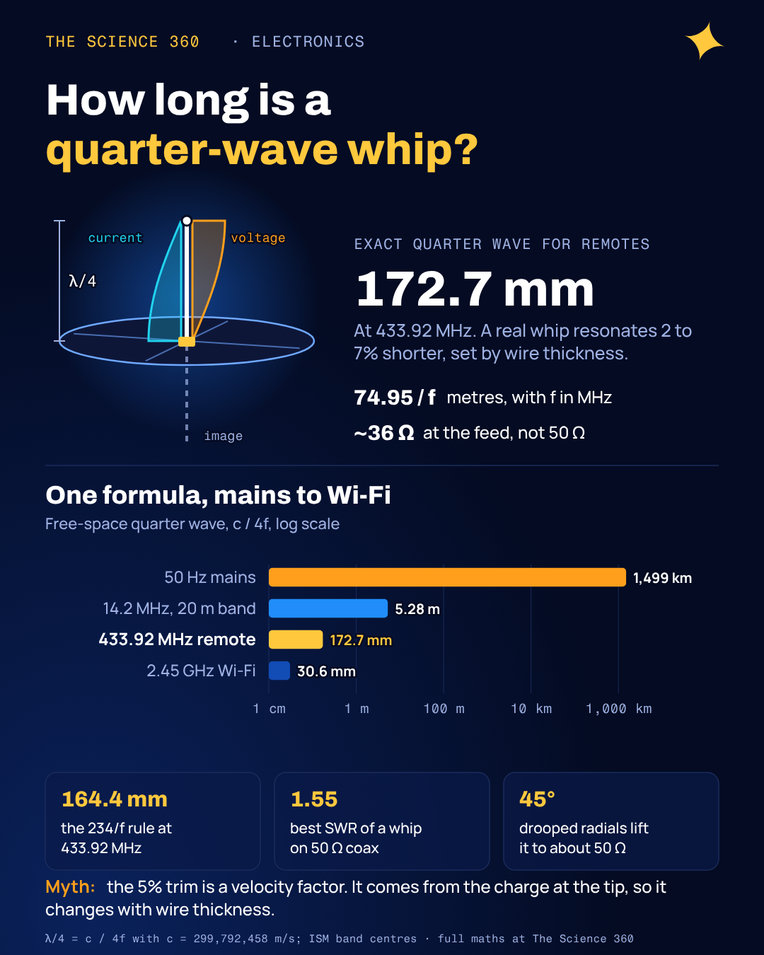 metres, f in MHz. A log bar chart shows the quarter wave at 50 Hz mains, 1,499 km; at 14.2 MHz, 5.28 m; at 433.92 MHz, 172.7 mm; and at 2.45 GHz, 30.6 mm. The 234/f rule gives 164.4 mm, a whip's best SWR on 50 ohm coax is about 1.55, and radials drooped to 45 degrees give about 50 ohms." width="1080" height="1350" loading="lazy" />
The quarter-wave formula, done properly
A wavelength is the speed of light divided by frequency, and the speed of light is defined as exactly 299,792,458 m/s. A quarter of that, with frequency in MHz:
In feet:
which rounds to .
The "234 rule" is a 4.9% shortening. Metric version of the 234 rule:
Calculators often print 71.5.
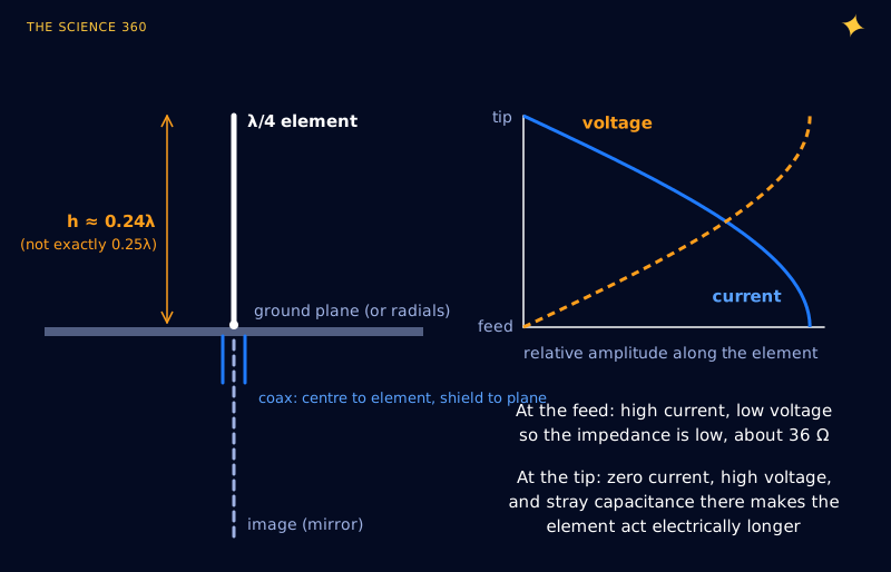
Why a quarter wave at all? A vertical element of height h over a conducting plane behaves like a dipole of length 2h, because the plane creates a mirror image of the element and of its current. A half-wave dipole is the shortest straight wire that is naturally resonant, so its half, the quarter-wave monopole, is too. The current is largest at the feed and falls to zero at the tip; the voltage does the opposite. That standing-wave pattern is the same one you see on any resonant line, and it is why the feed impedance is low.
The misconception: it is not a velocity factor
Velocity factor is a property of transmission lines. In a coax cable the field travels through a plastic dielectric, so the wave is slower than light, about 66% of it for solid polyethylene cable. That is a real slowing, and it makes a quarter-wave length of coax physically shorter than a quarter wave in air.
A bare wire in air has no such dielectric, so the signal along it travels at essentially the speed of light. Even Wikipedia's dipole article frames the shortening as a "reduced speed of radio waves in the conductor", and several of the calculator pages on page 1 call it a velocity factor of 0.95. The cause is different, and it shows up in the numbers.
The real cause is the antenna's own reactance. Cut a monopole to exactly λ/4 and its feed impedance is not purely resistive. The classic induced-EMF result is:
Exact λ/4 monopole over a perfect ground plane (half of the λ/2 dipole's ):
Slightly inductive.
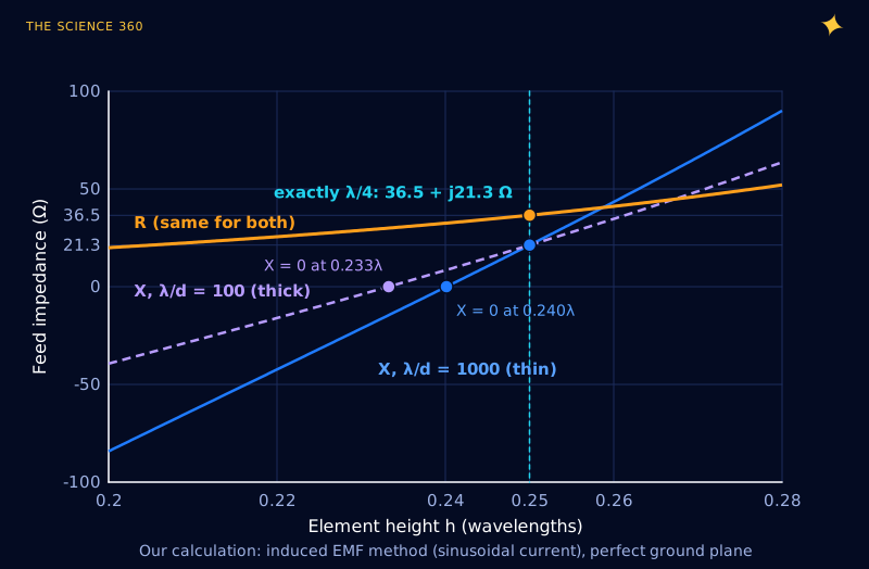
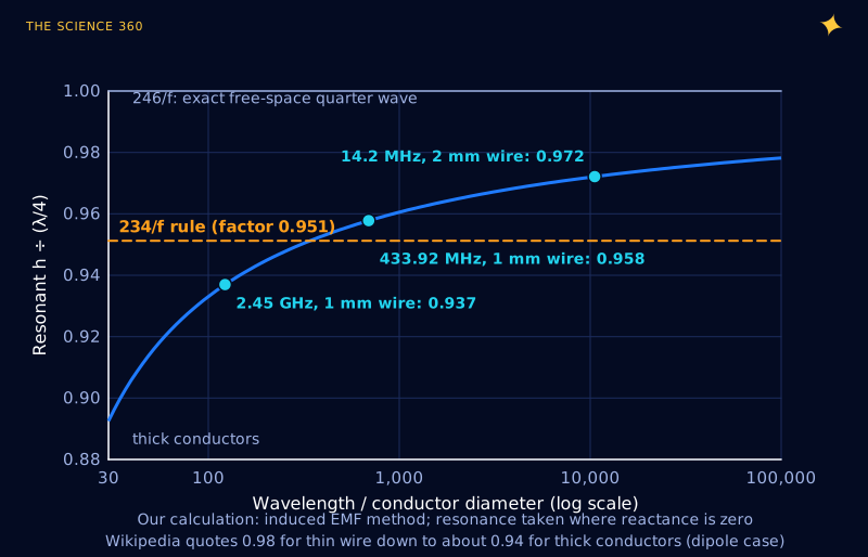
To cancel the +j21 Ω you shorten the element until the reactance passes through zero. How much shortening that takes depends on how fast the reactance changes with length, and that rate depends on the conductor's thickness. A thin wire has a steep reactance curve, so a small trim fixes it. A thick conductor has a shallow curve and needs a bigger trim. Physically, a fat element has more capacitance near its tip, the "end effect", which loads it like a capacitor hung on the end of a line. Wikipedia gives the dipole shortening factor as about 0.98 for thin wires down to about 0.94 for thick conductors. A true velocity factor would not care about thickness.
How the right shortening factor depends on wire thickness
Sweep the ratio of wavelength to conductor diameter and find where the reactance crosses zero each time, and you get a design chart (Figure 3). It is our own calculation with the induced-EMF formulas from Balanis, which assume a sinusoidal current; it is a good approximation for thin wires and becomes unreliable for very fat elements, so we stopped the curve at .
Worked example: a 433 MHz whip
The 433.05 to 434.79 MHz ISM band, centre 433.92 MHz, is used by remote controls, weather sensors and cheap transmitter modules. Here is the length three ways for a 1 mm copper wire:
for 1 mm wire. Free-space quarter wave:
234 rule:
Our model at : factor 0.958:
R = 32.3 Ω at resonance.
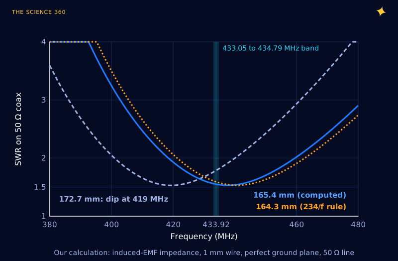
Here the rule of thumb and the model agree within about a millimetre, because a 1 mm wire at 433 MHz happens to sit near the thickness the rule describes. The real mistake is the one many hobby guides make: cutting the wire to 172.7 mm, the exact quarter wave, because "a quarter wave is a quarter wave". Figure 4 shows what that does.
Worked example: 2.4 GHz and an HF wire
At 2.45 GHz the wavelength is only 122 mm, so a 1 mm wire is relatively fat:
for 1 mm wire. 234 rule:
Our model: factor 0.937 → 28.7 mm (0.5 mm wire: 0.947 → 29.0 mm)
234 rule error for 1 mm wire:
Thirty-seven megahertz is still mostly inside a 2.4 to 2.5 GHz band, so a 2.4 GHz whip cut by the rule will work. A trace antenna on a circuit board is another matter: there the field passes partly through the board material, so a genuine dielectric slowing appears on top of the end effect, and the resonant length shrinks a good deal further. Use the chip vendor's reference layout rather than any formula here.
Now a thin wire on the 20 m amateur band, 14.0 to 14.35 MHz:
At 14.2 MHz:
2 mm wire gives . Our model: factor 0.972 → 5.131 m
234 rule:
That is 108 mm shorter. Resonance moves up by:
That is above the band edge.
This is why experienced builders say to cut long and trim. For a thin HF wire the 234 rule overcorrects. Insulated wire complicates the picture again, since the plastic jacket does add a real dielectric effect of a few percent, but that only reinforces the point: the correction is not one universal 0.95.
Why a quarter-wave whip is about 36 Ω, not 50 Ω
The monopole sees only half the space a dipole does, the half above the ground plane, so it radiates half the power for the same current and has half the radiation resistance: at exactly λ/4, and a little less, about 32 to 34 Ω, once trimmed to resonance. Feed that from 50 Ω coax and some power reflects:
A fifth of a decibel is nothing to worry about for most links, and it is why you should not chase a 1.0:1 SWR on a ground-plane antenna by trimming: no length gives it, and trimming for lowest SWR actually lands a little above the resonant frequency (Figure 4), because the resistance rises with length. The VSWR explainer covers what these numbers mean in practice.
If you do want 50 Ω, bend the radials down. The US amateur radio General exam pool states that sloping the radials of a ground-plane vertical down to about 45° raises the feed-point impedance from about 35 Ω to about 50 Ω. A tilted ground plane is less of a mirror, so the antenna starts to behave partly like a dipole, whose impedance is higher.
What counts as a ground plane?
The image trick only works if there is something to make the image. Wikipedia's monopole article puts it at a plane extending at least half a wavelength from the element, which is 35 cm at 433 MHz and 6 cm at 2.4 GHz. Three or four radials about a quarter wave long are the usual substitute. A small transmitter module on a 5 cm board has neither, so the board and its power leads become the other half of the antenna; its feed impedance drops and its resonance moves, and the only reliable length is the one you measure. Using the coax shield as the counterpoise also puts RF current on the outside of the cable, which is why such setups are sensitive to how the cable is routed.
Resistance in the element matters little for a full-size whip: a copper wire's RF resistance, set by the skin effect, is a fraction of an ohm against 32 Ω of radiation resistance. It matters a great deal for shortened, loaded antennas, where the radiation resistance falls to a few ohms.
For a sense of scale, the same formula says a quarter-wave antenna for 50 Hz mains would be 1,499 km tall (see why mains is 50 or 60 Hz), and at the 2.45 GHz of a microwave oven it is about 3 cm. An antenna is just a resonator with distributed L and C, the open-air relative of the LC tank circuit.
FAQ
How long is a quarter wave antenna?
A free-space quarter wavelength is metres, or feet, with f in MHz. A real resonant whip is a little shorter, typically 2 to 7% depending on how thick the conductor is relative to the wavelength. For 433.92 MHz the free-space value is 172.7 mm and a 1 mm wire resonates at about 165 mm.
What is the difference between 234/f and 246/f?
(feet, f in MHz) is the exact free-space quarter wavelength. is 95.1% of that, a rule of thumb for the shortening a real conductor needs to be resonant. The right factor depends on conductor thickness: about 0.97 for thin wire at HF and about 0.94 for a 1 mm wire at 2.4 GHz.
What is the impedance of a quarter wave antenna?
Over a large ground plane, an exactly quarter-wave monopole has about 36.5 Ω of resistance plus about 21 Ω of inductive reactance. Trimmed slightly shorter to resonance, it is about 32 to 35 Ω resistive. Sloping the radials down at about 45° raises it to roughly 50 Ω.
Does a quarter wave antenna need a ground plane?
Yes. A quarter-wave monopole is half of a dipole; the ground plane or radials supply the other half as a mirror image. Without one, the coax shield or the circuit board becomes the other half, and the length, impedance and pattern all change.
Related on The Science 360
Sources
- NIST CODATA, speed of light in vacuum, 299,792,458 m/s exact: physics.nist.gov/cgi-bin/cuu/Value?c
- Wikipedia, "Dipole antenna" ( for a true half-wave dipole; shortening factor about 0.98 for thin wires to about 0.94 for thick conductors; for ; attributes the shortening to reduced wave speed): en.wikipedia.org/wiki/Dipole_antenna
- Wikipedia, "Monopole antenna" (36.5 Ω for λ/4; element and image act as a dipole; ground plane at least half a wavelength; resonant length slightly shorter due to end effects): en.wikipedia.org/wiki/Monopole_antenna
- NCVEC General class question pool G9B02 and G9B03 via HamStudy (sloping radials raise the feed-point impedance from about 35 Ω to 50 Ω at 45°): hamstudy.org/browse/E3_2015/G9B
- Wikipedia, "ISM radio band" (433.05 to 434.79 MHz, centre 433.92 MHz; 2.4 to 2.5 GHz, centre 2.45 GHz): en.wikipedia.org/wiki/ISM_radio_band
- 66pacific.com, quarter-wave vertical calculator (typical page-one treatment: and citing the ARRL Antenna Book, radials at least a quarter wave, cut long and trim for best SWR): 66pacific.com quarter-wave calculator
- C. A. Balanis, Antenna Theory: Analysis and Design, Wiley, induced-EMF expressions for the radiation resistance and reactance of a finite dipole (the formulas used for Figures 2 to 4; we checked our code against the half-wave result rather than against the book itself).
Method note: Figures 2 to 4 were computed in Python with the induced-EMF formulas (sinusoidal current, perfect ground plane, monopole impedance = half the dipole's). Figure 1 is a schematic with the ideal sinusoidal current and voltage distributions.
Header image: NASA (image iss005e08718), regraded for this article.