Why Is AC Power 60 Hz (or 50 Hz)? The Real Tradeoffs
In 1886 the first commercial Westinghouse alternators had eight poles and spun at 2,000 rpm. Multiply it out and you get 16,000 alternations per minute, or 133⅓ cycles per second, which is what America's first AC lighting systems ran on. Nobody chose 133⅓ Hz because it was good. It fell out of a convenient armature design. Four years later a Westinghouse engineer sat down and worked out what the frequency should be, and the answer was 7,200 alternations per minute: 60 Hz.
That story, told by Westinghouse's chief engineer Benjamin Lamme in a 1918 paper, is more interesting than the version usually repeated online. It shows that 60 Hz is a compromise between competing pieces of physics, and the same tradeoffs explain why Europe settled on 50 Hz, why railways in Germany run on 16⅔ Hz, and why the airliner you flew on uses 400 Hz.
Where did 60 Hz come from?
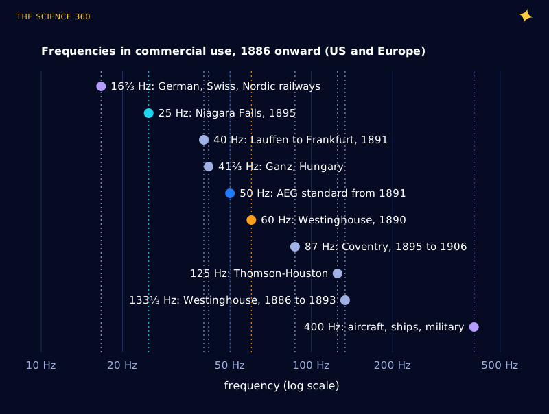
Early AC systems used whatever frequency their generators happened to produce. Figure 1 shows the spread: Thomson-Houston used 125 Hz, Coventry in England ran 87 Hz until 1906, the Hungarian firm Ganz used 41⅔ Hz (5,000 alternations per minute), and the 1895 Niagara Falls plant chose 25 Hz. London alone had ten different frequencies in 1918.
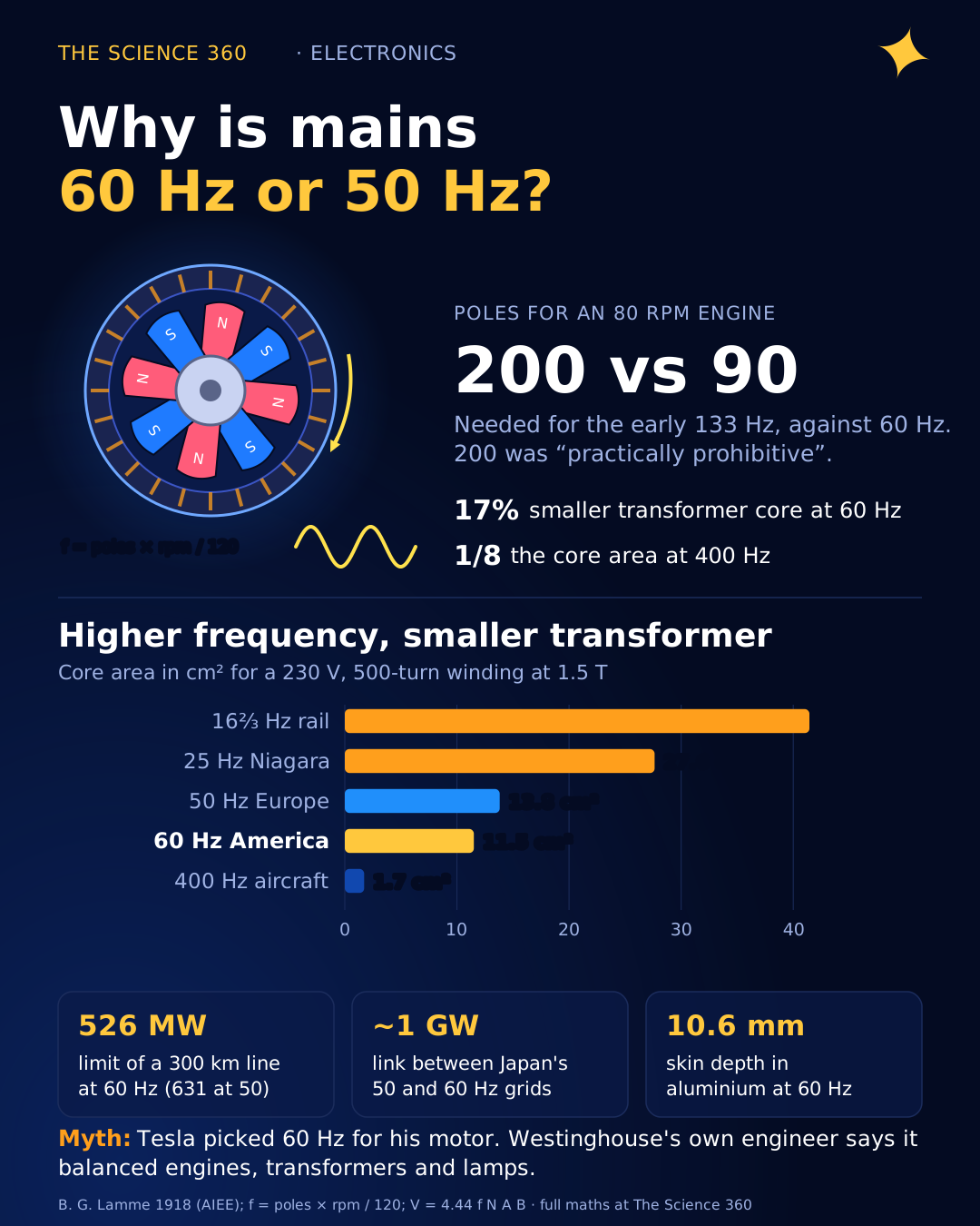
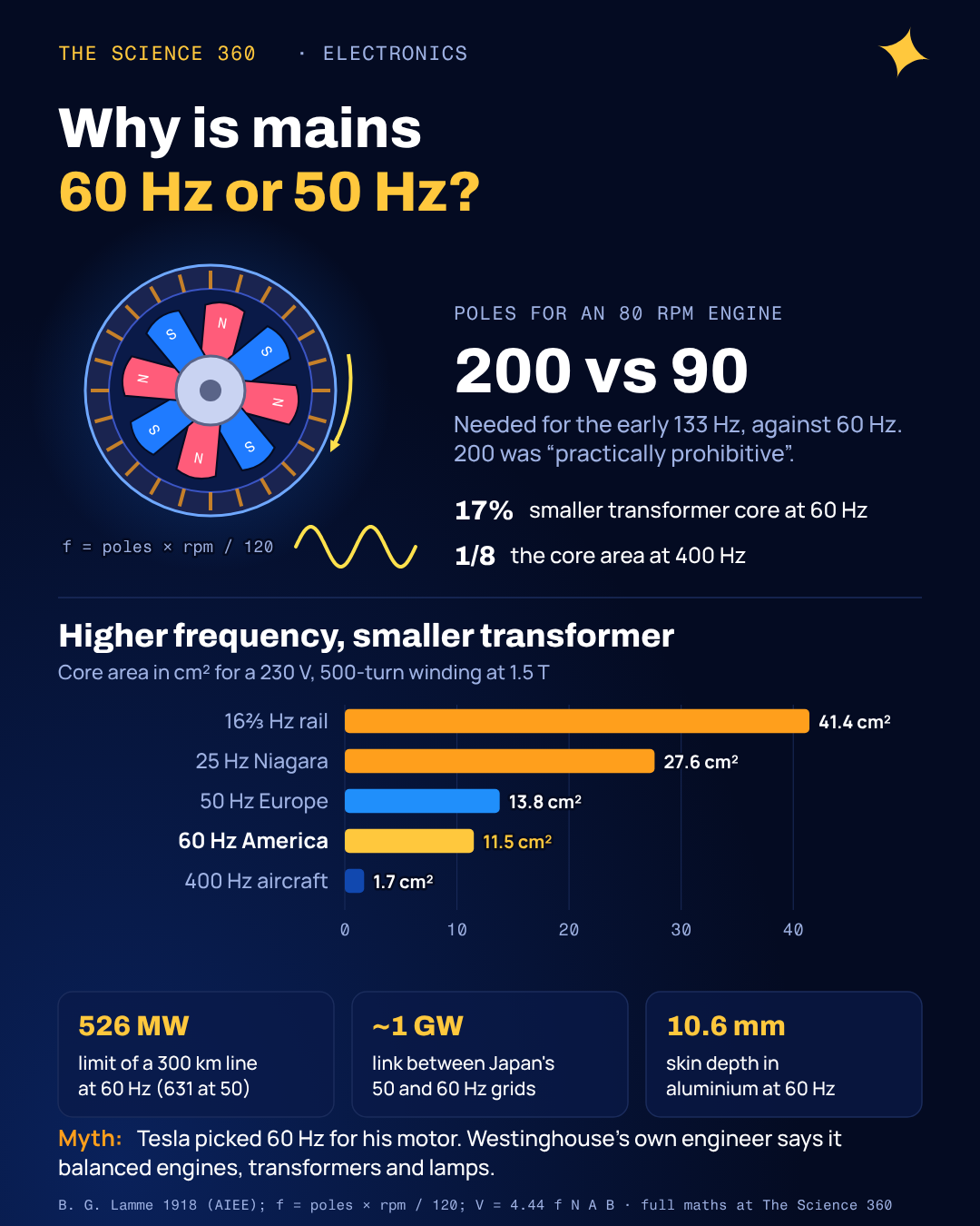
Lamme's account of the 60 Hz decision is specific. Around 1889 or 1890 it was becoming clear that 125 to 133 Hz was too high. Large, slow engine-driven alternators were coming, and a generator's frequency is set by its speed and pole count:
Generator frequency
An 80 rpm steam engine, direct-coupled
Lamme quotes the 200-pole figure himself and calls it "practically prohibitive". L. B. Stillwell, then at Westinghouse, studied the problem case by case and concluded that 7,200 alternations per minute "was about as high as would be desirable for the various engine speeds then in sight." Transformers and arc lighting were weighed in the same study: a somewhat higher frequency would have been better for transformers, a lower one for engine-type generators. In Lamme's words, "a compromise between all the various conditions eventually led to 60 cycles as the best frequency."
The Tesla myth
The most common answer online is that Nikola Tesla calculated 60 Hz to be the most efficient frequency for his induction motor, and Westinghouse adopted it for him. It makes a good story. The engineer who ran Westinghouse's engineering department says otherwise.
Lamme writes that adopting 60 Hz "was not considered as a direct means for bringing forward the polyphase induction motor, for the earlier 60-cycle systems, like the 125- and 133⅓-cycle, were all single-phase." He adds that the polyphase motor was thought to need "a still lower frequency," and that Westinghouse actually shelved its work on the Tesla motor in 1890 because there was no suitable supply system for it. The motor was revived in 1892 and found it could run happily on 60 Hz after all. So the induction motor shaped which frequency survived (60 Hz was low enough for it, 133 Hz was not), but it did not set the number. Frequencies around 60 Hz did suit his motors, which helped 60 Hz win out over 133 Hz. The specific number, though, came out of a broader engineering compromise.
Europe's number has its own story. AEG built the 1891 Lauffen to Frankfurt demonstration line, 175 km at 40 Hz, and saw lamp flicker. It raised its standard to 50 Hz. The often-repeated claim that 50 was picked because it is a round metric number may contain some truth, but the flicker observation is better documented.
Why does frequency change transformer size?
A transformer works because a changing magnetic flux in its iron core induces a voltage in the windings. The faster the flux changes, the more voltage you get per turn for the same peak flux. The standard design equation is:
= frequency, = turns, = core cross-section, = peak flux density (silicon steel saturates near 1.5 to 1.8 T).
The iron can only carry so much flux before it saturates, so is fixed by the material. That leaves . Halve the frequency and you need twice the core area or twice the turns. Here is a worked example for a winding with 500 turns.
Core area for a 230 V, 500-turn winding at 1.5 T
At 25 Hz it is 27.6 cm², and at 16⅔ Hz 41.4 cm². At 400 Hz the core is one eighth of the 50 Hz size.
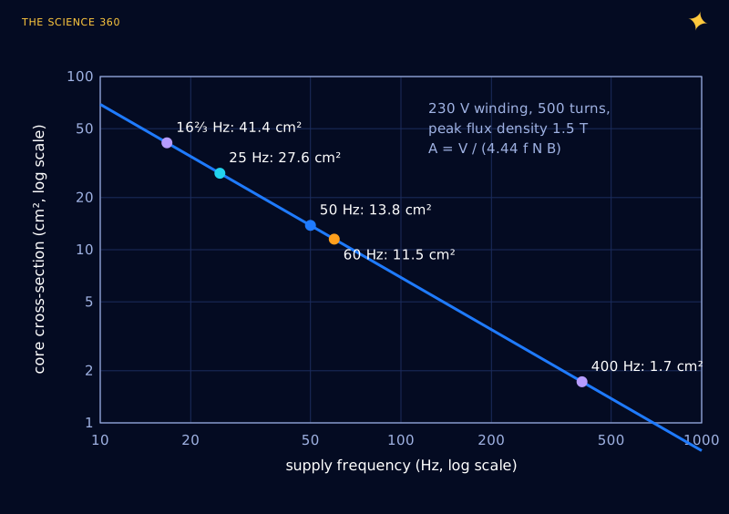
This is why the 1880s lighting engineers liked 133 Hz: they had thousands of small house transformers, and higher frequency meant less iron and copper in each one. It is also why the switch-mode charger for your phone runs its tiny transformer at tens or hundreds of kilohertz, not 50 Hz. The physics has not changed; only the electronics to generate high frequency cheaply has.
The flip side is core loss. Hysteresis loss per cycle is roughly fixed, so it grows in proportion to frequency, and eddy current loss grows roughly with the square of frequency. At higher frequency you need thinner laminations and a lower flux density. Nineteenth-century iron was poor enough that this limited how high anyone wanted to go.
Why does a lower frequency suit long power lines?
Two effects work against high frequencies on a power line. Both get worse in direct proportion to f or its square root.
Skin effect
Alternating current crowds toward the outside of a conductor. The depth at which current density falls to 1/e of its surface value is the skin depth:
Aluminium () at 60 Hz:
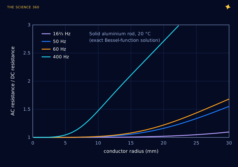
At 50 Hz: 11.6 mm. At 400 Hz: 4.1 mm. At 16⅔ Hz: 20.1 mm. Copper at 60 Hz: 8.4 mm; at 50 Hz: 9.2 mm.
Big transmission conductors have radii comparable to that skin depth, so the effect is real but modest at mains frequency. Figure 3 uses the exact solution for a solid round rod to show how much the AC resistance exceeds the DC value.
Line reactance
The bigger effect is inductance. An overhead line has an inductance of roughly 1 mH per km, and its reactance grows with frequency. The power an AC line can carry between two points is limited by the angle between the voltages at either end:
This is for a lossless line, in the short-line approximation.
345 kV line, 300 km, L = 1.0 mH/km, operated at θ = 30°
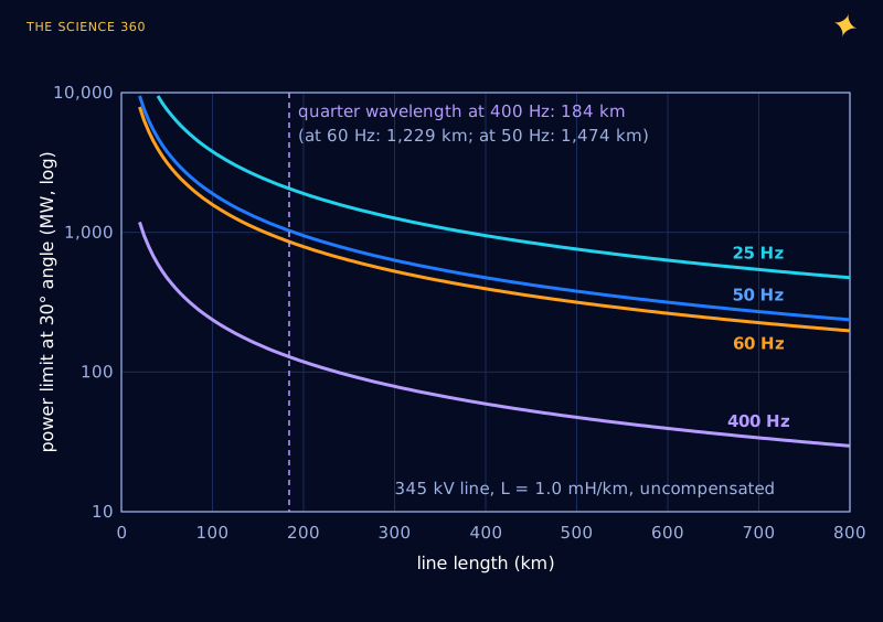
Real grids add series capacitors and reactive compensation to push these limits, and the very longest links now use HVDC, which sidesteps reactance entirely. But the basic scaling is why Niagara's 1895 engineers, who wanted to send power to Buffalo, picked 25 Hz. It is also why nobody runs a continental grid at 400 Hz.
Flicker and motors set the lower limit
If low frequency is good for lines, why not 25 Hz everywhere? Lighting. A lamp's power pulses at twice the line frequency, since power goes as voltage squared and peaks on both halves of the cycle. At 25 Hz that is 50 flashes per second, slow enough that an incandescent filament cools visibly between them and arc lamps flicker badly. That is exactly the problem AEG saw at 40 Hz on the Lauffen line. By 50 or 60 Hz (100 or 120 pulses per second) the flicker is below what most people notice for incandescent lamps, though fluorescent and cheap LED lamps can still show it in peripheral vision or on camera.
Motors pull in a similar direction. An induction motor's synchronous speed is rpm, so a two-pole motor runs at 3,000 rpm on 50 Hz and 3,600 rpm on 60 Hz. Lamme notes that the arrival of steam turbines, which like high speeds, pushed American utilities further toward 60 Hz: a four-pole 60 Hz turbo-generator turns at 1,800 rpm, a speed the early machines handled well. On 25 Hz the same machine would be limited to 1,500 rpm with two poles (the theoretical maximum for 25 Hz), and induction motors on 25 Hz were bulky for their power.
Same motor, 50 Hz versus 60 Hz
A centrifugal pump's power scales with speed cubed, so a pump designed for 50 Hz needs a smaller impeller, or a slower motor, on 60 Hz.
Why do aircraft use 400 Hz?
Put the tradeoffs together and an aircraft is the extreme case. Every kilogram costs fuel, the wiring runs are tens of metres rather than hundreds of kilometres, and there are lots of motors and transformers on board. So line reactance and skin effect barely matter, while transformer and motor size matter enormously. At 400 Hz, Figure 2 says a transformer core can be about one eighth of the area of a 50 Hz design for the same voltage and turns. Motors spin faster and deliver more power per kilogram.
That is why aircraft AC power, governed in the US military by MIL-STD-704, is 400 Hz, and why the same frequency turns up in ships, submarines, military ground equipment and old mainframe computer rooms (IBM used 415 Hz). Ground power carts at airports have to supply 400 Hz to a parked plane, which is why you see those dedicated cables plugged into the nose.
Going the other way, Germany, Austria, Switzerland, Sweden and Norway electrified their railways at 16⅔ Hz. Early AC traction motors were commutator motors, which spark and lose efficiency at higher frequency, and a low frequency suited them. Amtrak's Northeast Corridor and SEPTA still run sections on 25 Hz for similar historical reasons.
Why hasn’t the world standardised?
Because the differences are small and the switching cost is enormous. Brazil did it: a 1964 law moved the country from mixed 50 and 60 Hz to 60 Hz, and the conversion was finished in 1978. Southern California Edison ran 50 Hz until about 1948. Those were expensive, decade-long projects in grids far smaller than today's.
Japan is the cautionary tale of not standardising. In the 1890s Tokyo bought generators from AEG (50 Hz) and Osaka bought from General Electric (60 Hz). The country still runs two grids that can only exchange power through frequency converter stations. When the 2011 earthquake and tsunami took 9.7 GW of nuclear capacity offline in the east, the converters between the halves could handle only about 1 GW, so the west's spare capacity could barely help.
For most purposes the choice is a wash. 60 Hz equipment is about 17% smaller for magnetics; 50 Hz lines carry about 20% more power per unit of reactance. The bigger difference between US and European homes is the voltage (120 V versus 230 V), and that is a separate decision with its own history. If you were designing a grid from scratch today, you might pick something in the same range for the same reasons, and put HVDC on the long links.
FAQ
Did Tesla choose 60 Hz?
Not according to the engineers who were there. Westinghouse's B. G. Lamme wrote in 1918 that 60 Hz came from a study by L. B. Stillwell around 1890 that balanced engine-driven generators, transformers and arc lighting. The early 60 Hz systems were single-phase, and the induction motor was then thought to need an even lower frequency.
Is 50 Hz or 60 Hz better?
Neither is clearly better. 60 Hz allows transformers and motors about 17 percent smaller for the same rating and motors spin 20 percent faster. 50 Hz has slightly lower line reactance and skin-effect losses, so long lines carry a little more power. The differences are small enough that neither region has a reason to switch.
Why do airplanes use 400 Hz power?
Because transformer and motor size scale roughly inversely with frequency, so 400 Hz equipment can be several times smaller and lighter than 50 or 60 Hz equipment. On an aircraft every kilogram matters and the wires are only tens of metres long, so the extra line reactance and skin effect at 400 Hz do not matter.
Why does Japan use both 50 Hz and 60 Hz?
In the 1890s Tokyo bought generators from Germany's AEG (50 Hz) while Osaka bought from America's General Electric (60 Hz). The split survived, and the two grids are linked only through frequency converter stations, whose roughly 1 GW of combined capacity limited power sharing after the 2011 earthquake.
Can a 60 Hz appliance run on 50 Hz?
Most electronics with switch-mode power supplies are labelled 50/60 Hz and do not care. Induction motors run about 17 percent slower on 50 Hz, and simple transformers designed only for 60 Hz can overheat on 50 Hz because their core flux rises by 20 percent at the same voltage.
Related on The Science 360
Sources
- B. G. Lamme, "The Technical Story of the Frequencies," Proceedings of the AIEE, vol. 37, 1918 (133⅓ Hz from 8 poles at 2,000 rpm; Stillwell's 7,200 alternations study; 200-pole example; 60 Hz not chosen for the induction motor). PDF: zenodo.org/records/1554754 (DOI 10.1109/paiee.1918.6594479)
- Utility frequency (history of 25, 40, 41⅔, 50, 87, 125 Hz systems; AEG and Lauffen; Japan; Brazil; 16⅔ Hz rail; 400 Hz and MIL-STD-704; transformer size): en.wikipedia.org/wiki/Utility_frequency
- Energy in Japan (frequency converter capacity about 1 GW; 9.7 GW of reactors offline after 2011): en.wikipedia.org/wiki/Energy_in_Japan
- NPTEL, Equipment and Stability Constraints in System Operation (typical line L = 1.044 mH/km, C = 12 nF/km, surge impedance about 295 Ω): archive.nptel.ac.in course 108101040, module 2
- All About Circuits, "Why is the US standard 60 Hz?": allaboutcircuits.com/news/why-is-the-us-standard-60-hz
- Skin effect and the Bessel-function solution for a round conductor: en.wikipedia.org/wiki/Skin_effect
- Transformer EMF equation: en.wikipedia.org/wiki/Transformer
Method note: Figures 2 to 4 are computed from the equations shown. The line model in Figure 4 ignores resistance, compensation and the full distributed-line correction, so treat its numbers as an illustration of scaling rather than ratings for a real line.
Header image: NASA (image iss072e000922), regraded for this article.