Why Is Three-Phase Power Used? The Real Reasons
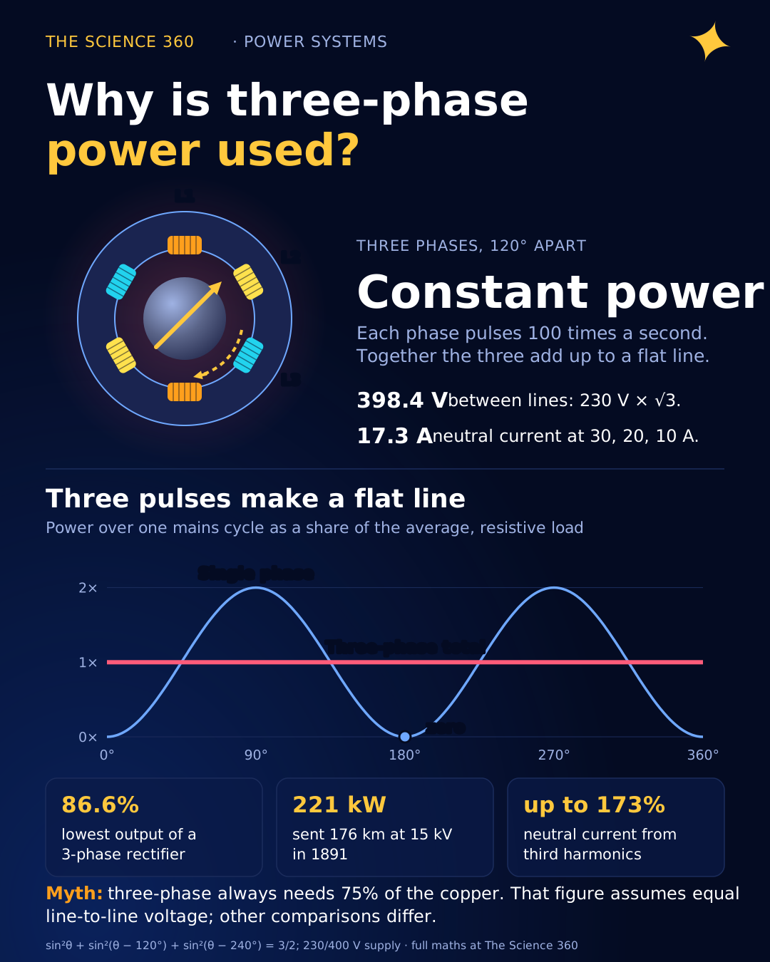
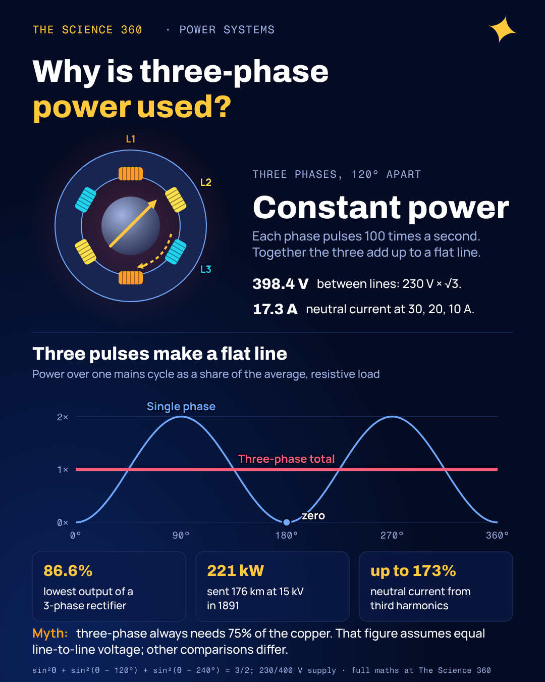
Put your hand on a single-phase fan motor and you can feel a faint 100 Hz buzz (120 Hz in North America). That is not a fault. Power in a single-phase circuit really does drop to zero 100 times a second and climb back to twice its average in between, and the motor's torque follows it. A three-phase motor of the same size is noticeably smoother, and the reason is a small piece of trigonometry: three sine-squared waves offset by 120° add up to a perfect constant.
The pages that rank for this question usually lead with a different reason: "three-phase uses less copper." That is true, but the famous percentages (75%, "three times the power with one extra wire") each assume a particular comparison, and change the comparison and the number changes. One fair comparison makes three-phase no better than the split-phase system in a North American house. The things three phases do that nothing simpler can are the constant power and the rotating field. Here are all three, with the numbers.
Why single-phase power pulses and three-phase does not
Feed a resistor from and the power is . Sine squared never goes negative, but it touches zero twice per cycle. Now add two more phases shifted by 120° and 240° and sum the three powers:
The three cosines are 240° apart, which is the same as three phasors 120° apart: they sum to zero. So the sum is 3/2 at every instant, and:
That is constant.
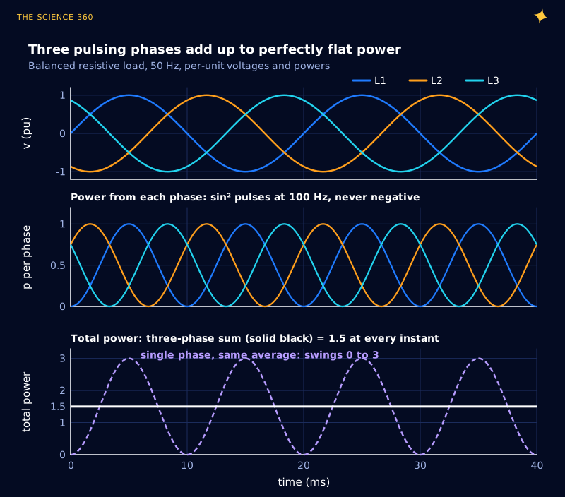
Why does constant power matter? A generator turbine or a motor shaft must carry torque equal to power divided by speed. With single-phase, that torque pulsates at 100 or 120 Hz, which shakes bearings, mountings and windings, and is part of why single-phase motors hum (the same 100 Hz you hear from a humming transformer, though there the cause is magnetostriction). A balanced three-phase machine sees steady torque. The Wikipedia summary of three-phase power puts it as: "Power transfer into a linear balanced load is constant, which, in motor/generator applications, helps to reduce vibrations."
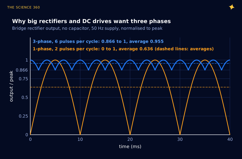
The same smoothing shows up when you rectify. A single-phase bridge gives two pulses per cycle that fall to zero; a three-phase bridge gives six that never fall below 86.6% of peak.
As fractions of the peak:
The 3-phase bridge has 13.4% ripple before any capacitor.
How three fixed coils make a rotating field
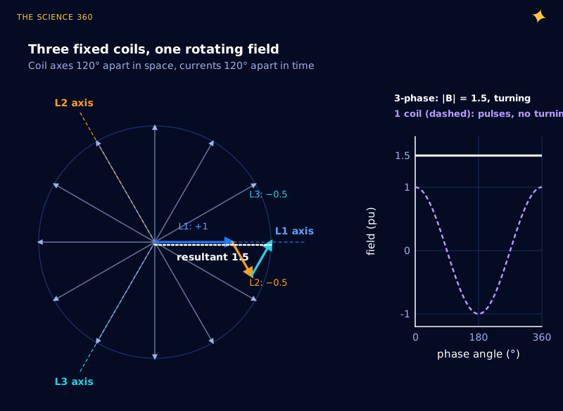
The second reason is what made three-phase win in the 1890s. Wind three coils around a motor's stator with their axes 120° apart in space, and drive them with currents 120° apart in time. Each coil's field only pulses back and forth along its own axis. Add the three as vectors and the result has constant length and turns smoothly at the supply frequency.
At θ = 0, coil L1 gives cos 0° = +1 along its axis; L2 and L3 give cos(−120°) = cos(120°) = −0.5 along theirs. Resolve along the L1 axis:
The perpendicular parts of L2 and L3 cancel. Repeat at any θ: magnitude 1.5, direction θ.
Put a conducting cage in that rotating field and the induced currents drag it round: the induction motor, which has no brushes and no commutator and is still the workhorse of industry. Wikipedia notes that the rotating field of "specified direction and constant magnitude" means "no starting circuit is required". Reverse any two phases and the field, and the motor, runs backwards. A two-phase supply (Ferraris's original motor was two-phase) can also make a rotating field, but its common wire carries about 1.4 times the phase current, and three-phase displaced it.
Does three-phase really use 75% of the copper?
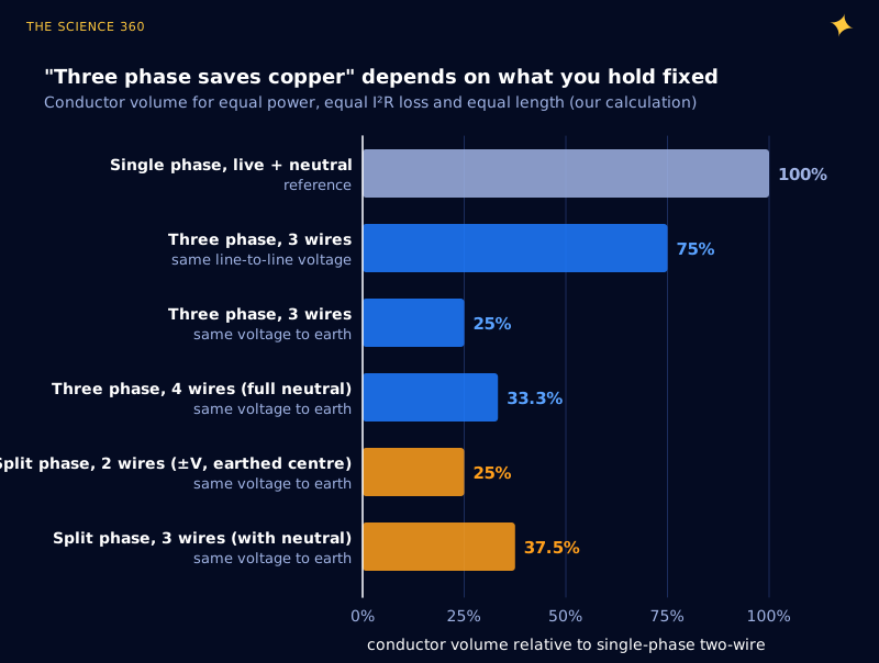
This is where most explanations get loose. The question is: for the same power, the same length and the same I2R loss, how much conductor do you need? The answer depends entirely on which voltage you hold equal, because insulation, safety and equipment are rated by voltage. Here is the derivation for the most quoted case, the same line-to-line voltage V:
Single phase, 2 wires, and three phase, 3 wires:
Equal loss means R3 = 2R1, so each three-phase wire has half the cross-section. Copper: 3 × ½ = 1.5 units against 2 units, or 75%.
That matches the 0.75 figure on Wikipedia, which is careful to say "at the same phase-to-phase voltage". But a 230/400 V system is not compared with a 400 V single-phase circuit in practice; it is compared with an ordinary 230 V live and neutral. Hold the voltage to earth at 230 V instead and three-phase looks far better, at 25% (33% with a full-size neutral). Then compare it with a centre-earthed single-phase pair, where each wire sits at 230 V to earth on opposite sides of zero, and the advantage vanishes: that also needs 25%.
Worked example: 23 kW over 50 m with 3% loss. Copper resistivity 1.72 × 10⁻⁸ Ω·m, all at 230 V to earth.
Single phase 230 V: I = 23,000/230 = 100 A, allowed loss 690 W, two conductors.
Three phase 230/400 V: I = 23,000/(3 × 230) = 33.3 A.
That is four conductors (full neutral), a third of the single-phase copper.
Real cables come in standard sizes and are also limited by heating, but the ratio holds. Voltage drop scales the same way, as the wire gauge for 12 V post shows at the other end of the voltage range, and it is the same logic that pushes transmission to high voltage.
Why is three-phase 400 V and single-phase 230 V?
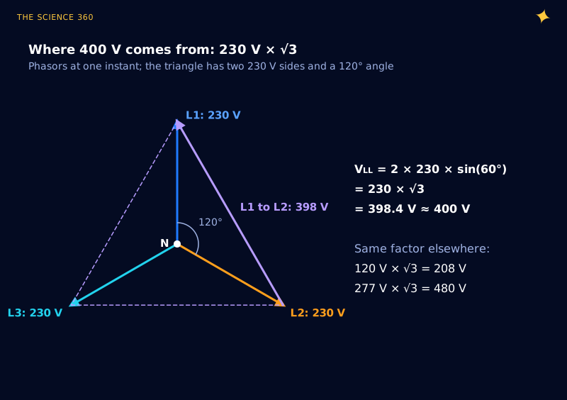
Both come from the same supply. Each line sits 230 V from neutral, and the lines are 120° apart, so the voltage between two lines is the third side of a triangle with two 230 V sides and a 120° angle.
The same √3 shows up in the power formula, which confuses people. Three-phase power is , which is just written with line voltage. It does not mean three-phase carries 1.73 times "more" than something.
A 32 A, 400 V three-phase supply at power factor 0.9:
The second line uses the exact 230 V. A 32 A, 230 V single-phase circuit at unity power factor gives .
What does the neutral carry?
In a perfectly balanced load, nothing: three equal currents 120° apart sum to zero, which is why high-voltage transmission lines need only three conductors. Homes are not balanced, so a 4-wire distribution feeder carries the phasor sum of the imbalance.
Phase currents 30 A, 20 A, 10 A (unity power factor):
There is a modern twist. Rectifier loads (computers, LED drivers, phone chargers) draw current in short pulses rich in the third harmonic. Shifting a fundamental by 120° shifts its third harmonic by 360°, so the three phases' third harmonics are exactly in phase and add in the neutral instead of cancelling. Ian Evans, writing in the IET's Wired In, notes this "can result in up to 173% of phase current levels, even if all phases are completely balanced", which is why office buildings sometimes have oversized neutrals.
Why three phases, not two or six?
Constant power is not unique to three: any balanced set of N ≥ 3 symmetric phases has it, and so does two-phase at 90° (). The trade-offs pick three:
Two phases need four wires to be independent, or three with a shared wire carrying √2 times the phase current, so they lose the neutral-cancellation trick. Six or twelve phases deliver smoother rectified DC, but every extra phase is another conductor, insulator string, breaker pole and transformer winding, for a ripple improvement that only very large rectifiers need. Those make their six or twelve pulses locally from three-phase with phase-shifting transformers. Three is the smallest number that gives constant power, a rotating field and zero neutral current with only three wires on the pylon.
History agreed quickly. Wikipedia credits Mikhail Dolivo-Dobrovolsky of AEG with a three-phase generator and motor in 1888, and the 1891 Lauffen to Frankfurt demonstration sent 221 kW at 15 kV over 176 km. The frequency those systems settled on is its own story, told in why AC is 50 or 60 Hz. And the reason a bird on one of those three wires is safe, while a hand bridging two would not be, is in why birds don't get electrocuted.
If you drive motors from DC instead, the electronics have to recreate those phases with switches; the single-phase version of that problem is the H-bridge motor driver, and a three-phase inverter is three half-bridges. At the high-current end, conductor size is also limited by the skin effect.
FAQ
Why is three-phase power used?
Three balanced phases deliver constant total power instead of power that pulses at twice the mains frequency, they create a rotating magnetic field that starts and drives induction motors without extra parts, and they move a given power with less conductor than an ordinary live-and-neutral circuit. Three is the smallest number of phases that gives all of this with no current in the neutral.
Why is three-phase 400 V and not 690 V?
The 400 V is the voltage between two lines, while 230 V is the voltage from each line to neutral. Two 230 V phasors 120° apart differ by , which is rounded to the nominal 400 V of IEC 60038. In North America the same factor gives 120/208 V and 277/480 V.
Does three-phase use less copper than single-phase?
It depends on what you hold equal. At the same line-to-line voltage, a three-wire three-phase circuit needs 75% of the conductor of a two-wire single-phase circuit for the same power and loss. At the same voltage to earth it needs 25%, or 33% with a full-size neutral. A centre-earthed split-phase circuit does as well on that basis.
Why not use six or twelve phases?
Three phases already give constant power, a rotating field and zero neutral current in a balanced load. More phases need more conductors, switchgear and transformer windings for little extra benefit. Six and twelve pulse arrangements are used inside large rectifiers, made from three-phase supplies with transformers.
Can the neutral current in a three-phase system be larger than the phase current?
Yes. Balanced sinusoidal currents cancel in the neutral, but third-harmonic currents from rectifier loads such as computers and LED drivers are in phase on all three lines and add. Harmonics specialists report neutral currents up to about 173% of the phase current in balanced systems with many such loads.
Related on The Science 360
Sources
- Wikipedia, "Three-phase electric power" (0.75 conductor at same phase-to-phase voltage, constant power into balanced load, rotating field with no starting circuit, neutral and triplen harmonics, two-phase common wire about 1.4 times, Dolivo-Dobrovolsky 1888, Lauffen to Frankfurt 1891 221 kW at 15 kV over 176 km): en.wikipedia.org/wiki/Three-phase_electric_power
- Wikipedia, "IEC 60038" (230/400 V replacing 220/380 V and 240/415 V, Amendment 1 of 1994, ±10% by 2003, 120/208, 277/480 and 120/240 V systems): en.wikipedia.org/wiki/IEC_60038
- Ian Evans, "Triplen harmonics" solution article, Wired In (IET), March/April 2007, hosted by Mirus International (neutral current up to 173% of phase current): mirusinternational.com PDF
- Electricity Forum, "3 Phase Power Explained" (typical page-one explanation): electricityforum.com/3-phase-power
Method note: all five figures are computed from the equations in the text with numpy. The conductor comparisons assume balanced resistive loads, identical conductors within each system and equal I2R loss; they are our calculations.
Header image: NASA (image GRC-1979-C-02443), regraded for this article.