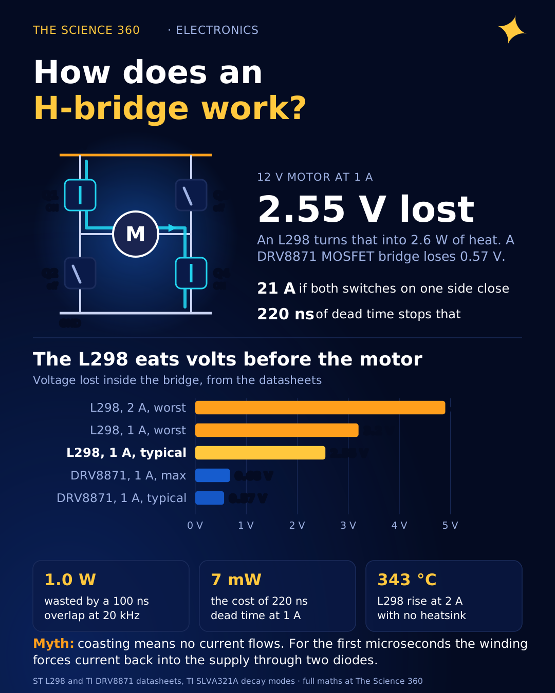
How Does an H-Bridge Work? Decay, Dead Time, Losses

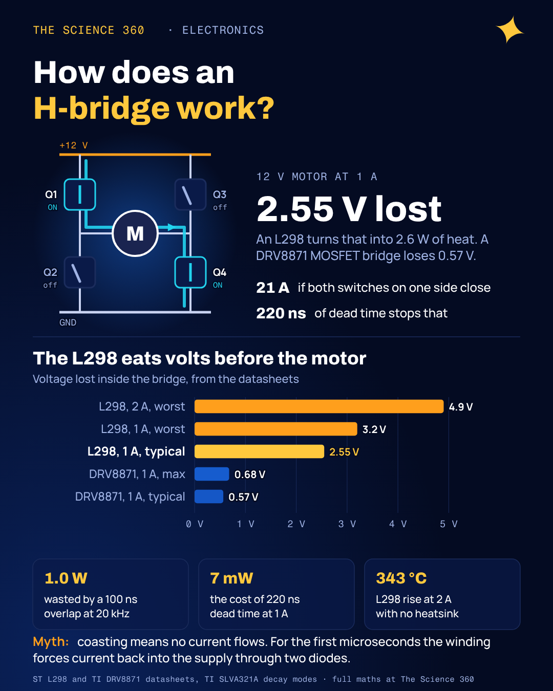
Wire a 12 V motor to the red L298N board every robotics kit ships with, run it at 1 A, and put a meter across the motor terminals. The datasheet says you should read somewhere between 8.8 V and 10.2 V. The missing volts become about 2.5 W of heat in a chip that has to sit under a finned heatsink to survive. A MOSFET driver doing the same job loses about half a volt.
Most explanations of the H-bridge stop at the truth table: four switches, close the diagonals to go forward or back, never close both switches on one side. That is correct and it is the easy part. What the switch diagrams leave out is what the motor's inductance does every time a switch opens, which is where shoot-through, dead time, the real difference between braking and coasting, and the strange speed curves you get from PWM all come from.
How does an H-bridge reverse a motor?
Figure 1 shows the circuit. Each side of the motor connects to a half-bridge: a high-side switch to the supply and a low-side switch to ground. Q1 and Q2 form the left leg, driving terminal OUT1; Q3 and Q4 form the right leg, driving OUT2. Draw it and it looks like a letter H with the motor as the crossbar.
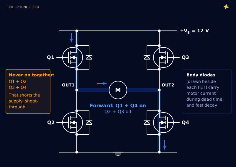
Turn on Q1 and Q4 and OUT1 sits at the supply while OUT2 sits at ground: current flows left to right through the motor and it turns one way. Turn on Q3 and Q2 instead and the voltage across the motor flips sign, the current reverses, and so does the torque. Integrated drivers hide this behind two logic pins. TI's DRV8871, for example, uses IN1 = 1, IN2 = 0 for forward (current OUT1 to OUT2), the reverse for reverse, 1 and 1 for brake, and 0 and 0 for coast.
The switches are almost always transistors. Old and cheap drivers such as the L298 use bipolar transistors; modern ones use MOSFETs. For a discrete bridge, the low-side switches are just low-side switches, driven like the ones in our posts on sizing a transistor base resistor and choosing a MOSFET gate resistor. The high-side switches are harder. An N-channel MOSFET between the supply and OUT1 needs its gate several volts above its source, and when it is on, its source is at the supply. So the gate has to go above the supply rail, which is why bridge driver chips contain a charge pump or bootstrap capacitor.
What is shoot-through, and why does dead time fix it?
Turn on Q1 and Q2 together and you have connected the supply to ground through two on-resistances and nothing else. Every forum warns about this, but it is worth putting a number on it because it explains why nobody ever does it on purpose and why it still happens by accident.
DRV8871 on-resistance, high side + low side: 565 mΩ typical. Shoot-through current at 12 V:
That is limited only by the supply and wiring. The normal rated peak output is 3.6 A.
The accidental version happens at every switching edge. Transistors do not switch instantly. If the controller turns Q2 on at the same moment it turns Q1 off, there is a short window where Q1 is still partly on and Q2 is already partly on. TI's application note on decay modes puts it bluntly: "there will be a short period of time in which all four FET switches will conduct. This is extremely hazardous to the device." Suppose each overlap lasted only 100 ns at 21 A. At 20 kHz PWM, with two edges per period:
That is pure waste at 20 kHz with two edges per period (our illustration, for a hypothetical 100 ns overlap).
A watt of heat with no useful output, in a chip that is supposed to dissipate half a watt in total. The fix is dead time: a short pause in which both switches of a leg are off before the other one turns on. The DRV8871 inserts 220 ns automatically. During that pause the motor current, which cannot stop instantly because of the winding inductance, flows through a body diode. The datasheet says exactly where: if current is leaving the pin, the output sits "a diode drop below ground", and if it is entering, a diode drop above the supply. That costs a little:
Dead-time conduction loss at 1 A, 20 kHz, through a 0.8 V body diode:
The duty error is per edge, as a share of the period.
Seven milliwatts is the price of not burning a watt. If you build a bridge from discrete MOSFETs and drive the gates from a microcontroller, you have to create this dead time yourself, either in the PWM peripheral (many motor-control timers have a dead-time register) or with a gate driver chip that enforces it.
What is the difference between braking and coasting?
Here is where page-one explanations usually go wrong. They say "short the motor to brake; open the switches and no current flows, so it coasts", which is true for what the motor does over the next second, and misleading about what happens in the next microsecond. Figure 2 shows the three states the bridge actually spends its time in when it runs a motor forward.
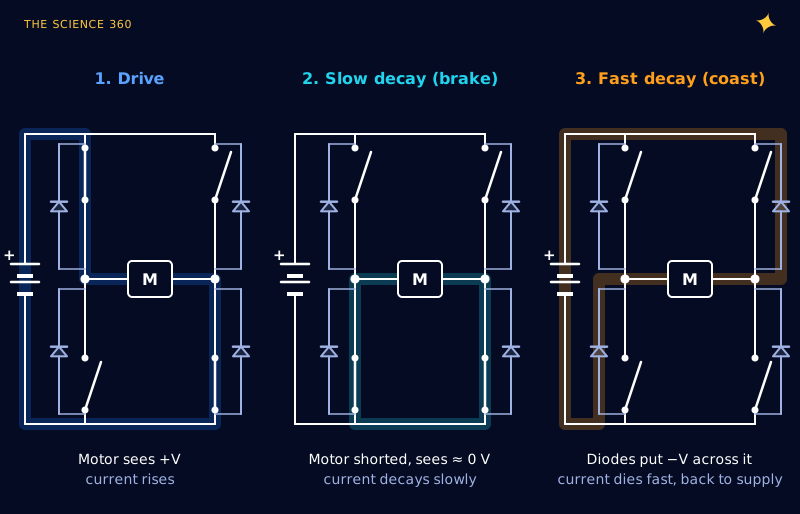
Brake, or slow decay (both low-side switches on). The motor terminals are shorted together through two on-resistances. Any current already flowing keeps circulating around the bottom of the bridge (green loop), decaying only as fast as the winding resistance lets it. TI notes it decays with the L/R time constant, where R includes two low-side on-resistances. If the motor is spinning, its back-EMF now drives current through that short, and the current produces torque opposing the rotation. The TI note describes it as a short that "collapses the back EMF" and gives "a very quick rotor stop". How hard? For the model motor used in this post's figures (2 Ω, 0.5 mH, spinning at 9,100 rpm with 9.5 V of back-EMF):
Brake current at full speed, and running current at the same speed:
Braking current is almost 4× the running current, and right at the DRV8871's 3.6 A peak rating.
So braking a large motor from full speed can stress the bridge harder than driving it. The kinetic energy ends up as heat in the motor winding and the two low-side switches.
Coast, or fast decay (all switches off). With every switch open you might expect the current to just stop. It cannot: the motor winding is an inductor, and an inductor's current cannot change instantly. The voltage rises until something conducts, and the somethings are the body diodes of Q2 and Q3 (orange loop). Current flows up from ground through Q2's diode, through the motor, and through Q3's diode into the supply rail. The motor now has the whole supply voltage plus two diode drops across it, in the direction that opposes the current, which is why the current collapses quickly. TI: "a voltage of greater magnitude but opposing polarity is applied to the inductive load."
Fast decay rate at 0.79 A, back-EMF 5.57 V (model motor):
Slow decay from the same point:
And the current would settle at a negative (braking) value instead of zero.
Once the current reaches zero the diodes stop conducting, the motor terminals float, and the rotor really does coast, with nothing but friction slowing it. So "coast" is accurate on a human timescale, but for the first tens of microseconds it is the most violent of the three states, and the energy stored in the winding goes back into the supply. With a battery that is harmless. With a bench supply or a regulator that cannot sink current, it pumps up the supply rail, which is one reason motor drivers want a large bulk capacitor right at the bridge as well as the usual 100 nF decoupling.
The L298 makes this point the hard way: it has no body diodes, because bipolar transistors do not have them. ST's datasheet requires an external bridge of four fast-recovery diodes (trr ≤ 200 ns) whenever it drives an inductive load, the same job a flyback diode across a relay coil does. Leave them out and the coil's turn-off voltage has nowhere to go but through the transistors.
How does PWM speed control interact with decay mode?
Speed control means switching between drive and one of the decay states tens of thousands of times a second. Each half of a leg is then doing the same job as the switch and diode in a buck converter, with the motor winding as the inductor; our buck converter post uses the same volt-second reasoning. Which decay state you pick for the off-time matters a lot more than most tutorials admit.
Figure 3 simulates the current in our model motor over three PWM periods at 60% duty and 20 kHz, holding the back-EMF constant (the rotor cannot change speed in 150 µs).
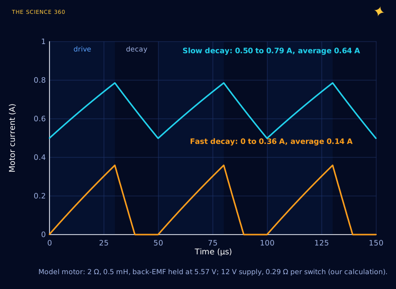
With slow decay, the motor current never stops. Over a period the motor sees the supply for a fraction D of the time and a near short for the rest, so the average voltage is . The ripple follows from the inductor equation:
Slow decay ripple (peak to peak):
The simulation agrees: 0.50 to 0.79 A, 0.29 A. D = 0.5 is the worst case. At f = 1 kHz the same formula gives 6 A, larger than the average current, so the current goes discontinuous.
With fast decay, the off-time applies the supply in reverse, so the current falls about as fast as it rose, hits zero and stops there (the diodes will not pass reverse current). Even if it stayed continuous, the ripple formula gains a factor of two, because the off-time voltage is −VS instead of zero. In practice the current becomes a string of separate pulses whose size depends on the back-EMF, the inductance and the PWM frequency.
That has a visible consequence: the speed you get for a given duty cycle. Figure 4 solves for the steady speed of the model motor against a simple friction-plus-viscous load at every duty cycle.
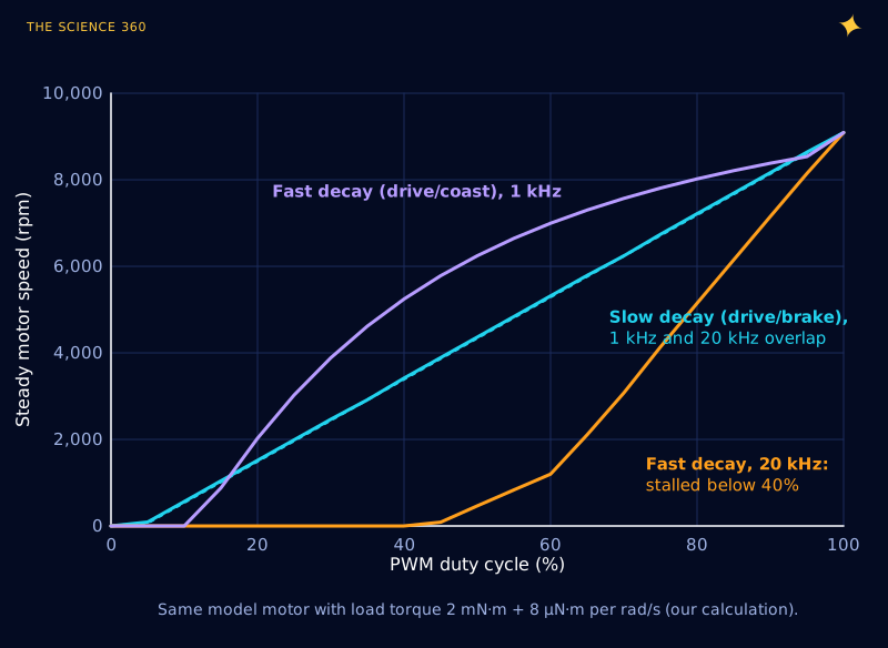
This is the practical upshot. If you drive an L298N board with PWM on the enable pin, the bridge turns all its transistors off in the off-time: that is drive/coast, fast decay. The speed then depends on the PWM frequency as much as on the duty cycle, and raising the frequency to get rid of motor whine can leave the motor stalled at duty cycles that used to work. PWM on an input pin with the enable held high gives drive/brake instead, which is what the DRV8871 datasheet recommends. The DRV8871 datasheet says "it typically works best to switch between driving and braking."
Why does an L298 lose so many volts?
Because each current path goes through two bipolar transistors in saturation, and bipolar transistors at amp-level currents do not saturate cleanly. ST's L298 datasheet (Tj = 25 °C) specifies:
VCE(sat) in volts (min, typ, max):
Source is the high side, sink the low side. Total drop: 1.80 V min to 3.2 V max at 1 A, and 4.9 V max at 2 A.
Adding the typical source and sink figures gives about 2.55 V at 1 A and 3.7 V at 2 A. Compare a MOSFET bridge, whose loss is a resistance:
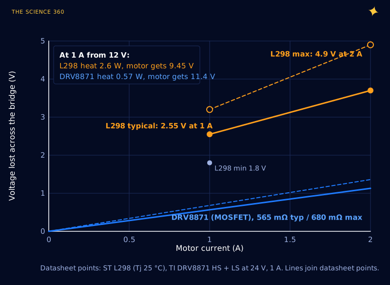
12 V motor at 1 A
Each row is the bridge drop, the voltage the motor gets, and the bridge heat (DRV is the DRV8871). The DRV8871 drop is 0.565 Ω × 1 A typical, and 360 + 320 mΩ at maximum.
At 2 A, L298 worst case:
That is per bridge, with no heatsink (35 °C/W junction to ambient). It needs the heatsink.
On a 12 V supply, the L298 throws away a fifth to a quarter of your voltage before the motor sees any of it, and on a 5 V or 6 V supply it can eat half. That is the real reason robot kits with L298N boards feel sluggish on small batteries. The heat side of the calculation is the same thermal-resistance chain as in our heatsink sizing post: 2.6 W into the L298's Multiwatt power package is manageable with a heatsink, 9.8 W needs a serious one. For a battery-powered robot the lost volts are also lost run time, and a pack's current rating (see LiPo C rating explained) does not help if a quarter of the energy warms the driver.
The L298 still has honest uses: it tolerates up to 46 V, it is forgiving, and its sense pins make simple current control easy. But for anything below about 2 A on a modest supply, a MOSFET driver wins on every number in the box above. The same logic applies to stepper drivers, which are two H-bridges with current regulation; our A4988 Vref calculation post covers how they choose between the decay modes on the fly.
A checklist for using an H-bridge
FAQ
How does an H-bridge reverse a motor?
An H-bridge has two half-bridges, one on each motor terminal. Turning on the top-left and bottom-right switches puts the supply across the motor one way; turning on the top-right and bottom-left puts it across the other way, so the current and the direction of rotation reverse.
What is shoot-through in an H-bridge?
Shoot-through is when the high-side and low-side switch on the same side conduct at the same time, shorting the supply to ground through two on-resistances. With a 565 mΩ bridge on 12 V that is about 21 A. Drivers prevent it with dead time, a short gap such as the DRV8871's 220 ns when both switches are off.
What is the difference between braking and coasting with an H-bridge?
Braking turns on both low-side (or both high-side) switches, shorting the motor so its back-EMF drives a current that slows it hard; in PWM this is called slow decay. Coasting turns all switches off; the motor current is forced through the body diodes back into the supply and dies within microseconds, after which the motor spins freely. In PWM this is fast decay.
Why does an L298 get so hot?
The L298 uses bipolar transistors, and each conducting path drops two saturation voltages. ST specifies a total drop of 1.8 to 3.2 V at 1 A and up to 4.9 V at 2 A. At 1 A that is roughly 2.5 W of heat, against about 0.57 W for a MOSFET driver like the DRV8871.
What PWM frequency should I use for an H-bridge?
High enough that the current ripple is small compared with the average current, which depends on the motor inductance: ripple is about in slow decay. Around 20 kHz is common because it is above most people's hearing. Use drive and brake (slow decay) PWM if you want speed roughly proportional to duty cycle.
Related on The Science 360
Sources
- Texas Instruments, DRV8871 3.6-A Brushed DC Motor Driver datasheet, SLVSCY9B (565 mΩ typical HS + LS, 307/360 mΩ and 258/320 mΩ per switch, 220 ns dead time, body diode 0.8 V at 1 A, truth table for forward, reverse, brake and coast, "switch between driving and braking"): ti.com/lit/ds/symlink/drv8871.pdf
- Texas Instruments, SLVA321A, "Current Recirculation and Decay Modes" (fast decay, slow decay, dead time, shoot-through hazard, L/R decay with 2 RDS(on), back-EMF collapse): ti.com/lit/an/slva321a/slva321a.pdf
- STMicroelectronics, L298 Dual Full-Bridge Driver datasheet (source and sink VCE(sat), total drop 1.8 to 3.2 V at 1 A and 4.9 V max at 2 A, 46 V operating, 2 A DC per channel, Rth j-amb 35 °C/W, external fast-recovery diodes trr ≤ 200 ns): sparkfun.com copy of the ST L298 datasheet
- Typical page-one explainer (coasting described as "no current flows" and the motor "rotates freely"; no mention of dead time or diodes): CircuitBread, "How does an H-bridge work?": circuitbread.com/ee-faq/how-does-an-h-bridge-work
Method note: Figures 3 and 4 are our own time-step simulations of a brushed DC motor (series R, L and back-EMF) on an H-bridge with resistive switches and 0.8 V diodes, solved to a periodic steady state at each duty cycle; Figure 4 then finds the speed where motor torque equals load torque. The shoot-through power and braking current are our arithmetic from the datasheet values.
Header image: NASA/JPL-Caltech/MSSS (image PIA21486), regraded for this article.