Relay Flyback Diode: Why You Need One and Which to Use

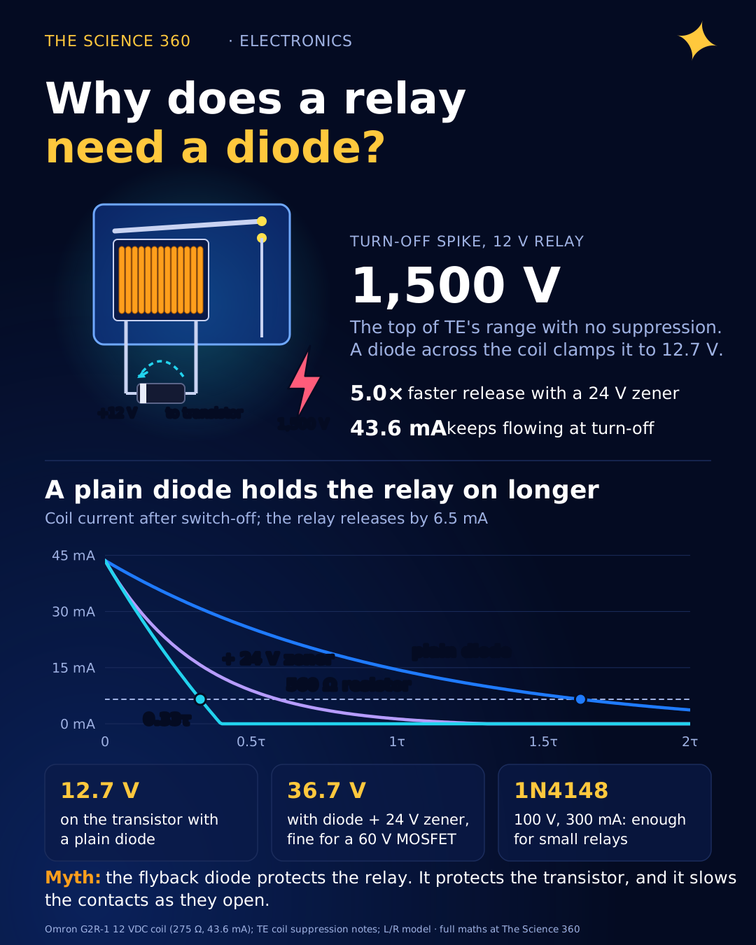
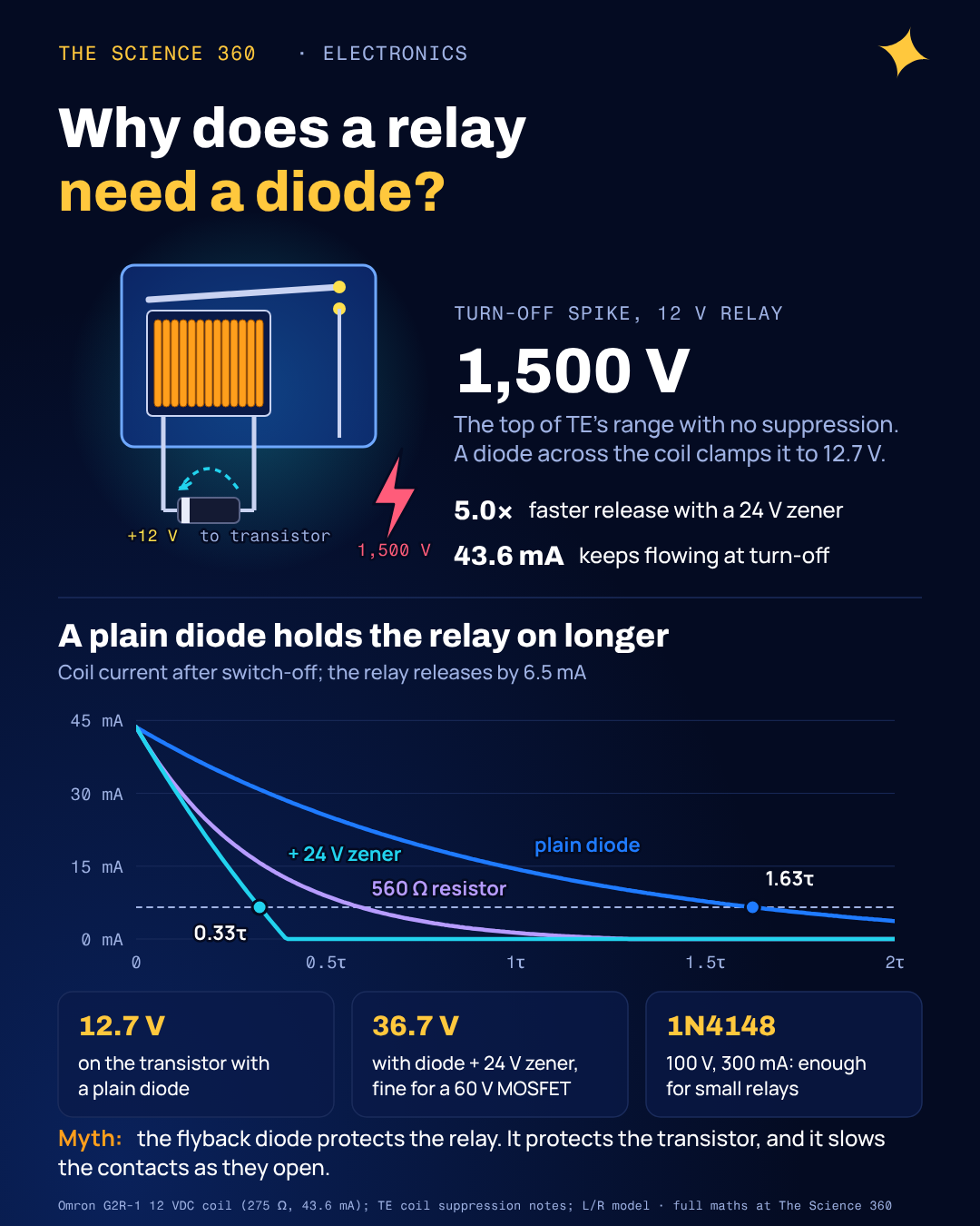
A 12 V relay coil draws a modest 43.6 mA. Switch it off with a transistor and, for a few microseconds, the coil tries to keep that 43.6 mA flowing through whatever it can find. TE Connectivity, one of the largest relay makers, says a 12 V relay can generate 1,000 to 1,500 V at turn-off. That is why every relay circuit you have ever seen has a diode across the coil.
What most tutorials skip is that the diode has a cost. It makes the relay release later and its contacts open more slowly, and TE goes as far as saying its impact on relay performance "can be devastating". There is a two-part fix that costs one extra component. This post works through both, with real coil numbers.
Why does a relay coil create a voltage spike?
An inductor obeys . While the relay is on, the coil stores energy in its magnetic field, and the current through it cannot change instantly without an infinite voltage. When your transistor turns off in a microsecond or so, it asks the current to go from 43.6 mA to zero in that time. The coil answers with whatever voltage is needed to keep the current flowing.
Our example is an Omron G2R-1 12 VDC power relay: 275 Ω coil, 43.6 mA rated current, 5 ms maximum release time. Omron does not publish the coil inductance, so for the worked numbers below we assume L = 0.5 H. That figure is our assumption for illustration, not a datasheet value. The important ratios in this post do not depend on it, and the end of the post shows how to measure yours.
What the coil "wants" if the switch opens in 1 µs
Energy that has to go somewhere
It never actually reaches 22 kV. Long before that, something breaks down: the transistor avalanches, or the stray capacitance of the winding and wiring charges up and rings. That is why measured spikes land at hundreds to about 1,500 V. The energy is tiny, under a millijoule, but dumping it repeatedly into a transistor rated for 40 or 60 V is how relay drivers die after a few thousand cycles. The same physics, inductor current refusing to change instantly, is what makes a buck converter work, used there on purpose.
What does a flyback diode actually do?
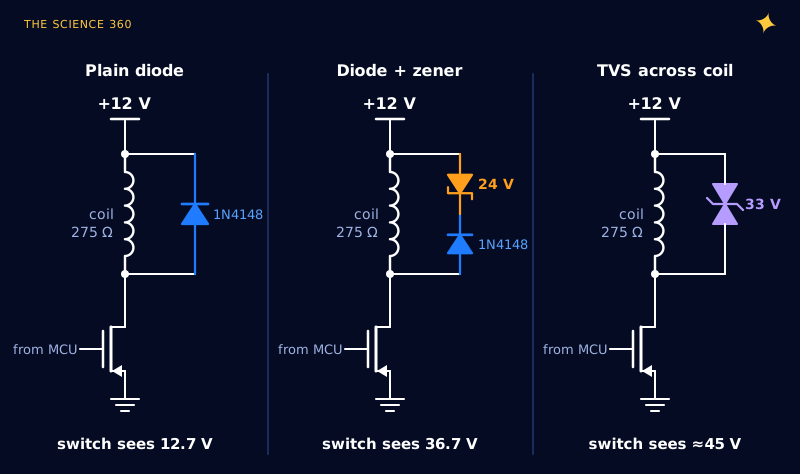
The diode sits across the coil, reverse-biased while the relay is on, so it does nothing. At turn-off, the coil voltage reverses (the bottom of the coil swings above the supply) and the diode becomes forward-biased. Now the coil current circulates round a small loop, coil to diode and back, and the voltage at the transistor is clamped to the supply plus one diode drop: 12.7 V instead of a kilovolt.
The coil current then decays through the coil's own resistance. With nothing but 275 Ω and 0.7 V opposing it, that decay is slow, with time constant . That slowness is the hidden cost.
The misconception: “the flyback diode protects the relay”
The diode protects the transistor. It does nothing for the relay, and it actively hurts the relay's contacts.
A relay releases when the magnetic pull falls below the return spring's force. The magnetic pull follows the coil current. With only a diode, the current lingers, so the armature lets go later, and it accelerates away more slowly because the field is still partly holding it as it moves. Contacts that separate slowly draw a longer arc, especially when they are breaking a DC or inductive load. TE's application notes describe the result as random "tack welding" of normally-open contacts and recommend against diode-only suppression for relays that switch real loads.
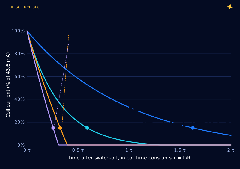
We can put numbers on the delay. After switch-off, the circuit is the coil's inductance and resistance in series with a fixed clamp voltage Vclamp (0.7 V for a diode, 0.7 V plus VZ with a zener). Solving :
Time to fall to the release current Ir:
We use the G2R's guaranteed must-release level, 15% of rated: .
Plain diode (Vclamp = 0.7 V):
Diode + 24 V zener (Vclamp = 24.7 V):
Ratio: 1.63 / 0.33 = 5.0× faster with the zener. With the assumed L = 0.5 H, , so 3.0 ms versus 0.6 ms.
Three milliseconds of extra delay may sound harmless, but compare it with the G2R's own release-time specification of 5 ms maximum. The diode can add more delay than the relay's whole rated release time, and worse, the contacts move slowly during the opening that matters for arcing.
The first-order model leaves out one effect that only helps the argument: as the armature moves away, the magnetic gap opens, the inductance drops, and the moving armature induces a back-voltage of its own. A fast-collapsing current lets that motion happen quickly. A slowly decaying one fights it.
How does a diode plus zener fix it?
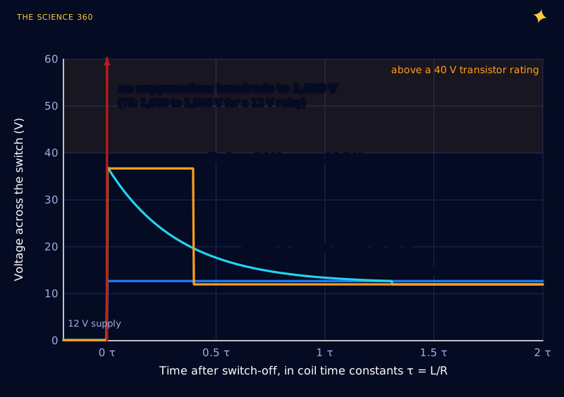
Put a zener diode in series with the flyback diode, cathode to cathode, as in the middle of Figure 1. During normal operation the rectifier diode blocks. At turn-off, the current flows forward through the rectifier and backward through the zener, which holds its breakdown voltage VZ. The coil now has 24.7 V pushing its current down instead of 0.7 V, and the energy is dumped about five times faster.
The price is a higher voltage on the switch: the supply plus the diode drop plus VZ. Figure 3 shows the trade.
How to choose the zener voltage
Work backwards from your switch's voltage rating:
60 V MOSFET, 80% derating, 12 V supply that can reach 14.4 V:
That calls for a 24 V or 27 V zener. With a 40 V transistor:
That calls for a 15 V zener.
Power is not a concern for a small relay. The zener only sees the coil current (43.6 mA peak) for well under a millisecond per release. A 1 W part such as the 1N4749A (24 V) is generous. For relays switched many times a second, multiply the coil energy by the switching rate and check the average.
Comparing the alternatives: diode, resistor, zener and TVS
TE lists four practical options, and they all fit the same equation with a different clamp. A resistor Rs in series with the diode gives a clamp that starts at I0Rs and shrinks as the current decays; TE's sizing rule is simply . A TVS across the coil is effectively a zener that works in both directions and needs no separate diode.
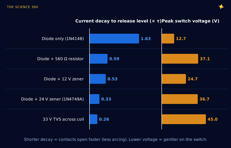
Notice that the 560 Ω resistor and the 24 V zener both put about 37 V on the switch, but the zener releases nearly twice as fast. A resistor's clamp voltage falls with the current, so it is strong at the start and weak when you need it most. A constant clamp spends the whole voltage budget all the way down.
When is a plain diode the right answer? TE notes that when the important load is on the normally-closed contact, slower armature motion can actually reduce contact bounce on closing. A plain diode is also fine when the contacts switch low-power signals, when release timing does not matter, or for very small signal relays where arcing is negligible.
Which diode should you use for a relay?
- Reverse voltage above the coil supply, with margin. Anything 50 V or more covers 5 to 24 V coils.
- Current at least the coil current. Peak flyback current equals the coil current at turn-off and only decays from there.
- Speed does not matter much. Relay coils switch in milliseconds, not nanoseconds.
A Vishay 1N4148 is rated 100 V, 300 mA continuous and 2 A for a 1 µs surge, which covers most PCB relays up to a few watts of coil. A 1N4007 (1,000 V, 1 A) is the universal choice for larger contactor coils. Mount it right at the relay, not back at the driver, so that the current loop is small and the spike never travels down your wires. And check the orientation: stripe to the positive side. Backwards, the diode shorts the supply through your transistor the moment the relay turns on.
How do you measure your relay’s time constant?
Because the conclusions scale with τ, it is worth measuring. TE describes the method: apply rated DC voltage while holding the armature seated, and time how long the coil current takes to rise to about 63% of its final value. That time is τ, and . With a 1 Ω sense resistor in the ground return and a scope, it takes five minutes. Inductance is higher with the armature seated than open, and it varies with drive level, so measure at rated voltage.
Do solid state relays need a flyback diode?
The input of a solid state relay is an LED, not a coil, so there is nothing to suppress on the control side. The output is a different story. A DC SSR (a MOSFET inside) that switches a solenoid, motor or another relay coil sees exactly the same kickback from that load, so it needs a diode or TVS across the load. AC SSRs switching inductive loads usually need a snubber or varistor instead; follow the maker's guidance.
FAQ
Do I need a flyback diode on a relay?
Yes, whenever a transistor or IC switches the coil. When the coil current is interrupted the inductance drives the voltage up until something conducts; TE Connectivity notes a 12 V relay can generate 1,000 to 1,500 V. A diode, diode plus zener, TVS or resistor across the coil gives that current a safe path.
Which way does the flyback diode go on a relay?
Reverse-biased during normal operation: the cathode (the striped end) goes to the positive supply side of the coil and the anode to the side connected to the switching transistor. Installed backwards it short-circuits the supply through the transistor as soon as the relay is switched on.
What diode should I use for a relay coil?
Any silicon diode whose reverse voltage rating exceeds the coil supply and whose current rating covers the coil current. A 1N4148 (100 V, 300 mA continuous) suits small 5 V and 12 V relays; a 1N4007 (1,000 V, 1 A) suits larger coils. Speed is not critical for relay coils.
Does a flyback diode slow down a relay?
Yes. With only a diode across the coil, the current decays slowly through the coil's own resistance, so the armature releases later and the contacts open more slowly. For a 12 V coil the current takes about five times longer to reach the release level than with a 24 V zener added in series with the diode.
Do solid state relays need a flyback diode?
Not on the input, which is an LED rather than a coil. But a DC solid state relay that switches an inductive load such as a solenoid or motor still needs suppression across that load, because the load's inductance produces the same kickback the relay coil would.
Related on The Science 360
Sources
- TE Connectivity, "Relay Coil Suppression with DC Relays" (1,000 to 1,500 V for a 12 V relay; diode-only effect on contacts; diode plus zener recommendation; resistor sizing R = Vpeak / Icoil; TVS clamping): te.com relay coil suppression
- TE Connectivity, "Coil Suppression Can Reduce Relay Life" (slowest flux decay with a simple diode shunt; near-optimal with a zener in series): te.com coil suppression and relay life
- TE Connectivity, "Determining Relay Coil Inductance" (L = tR method; seated versus unseated armature): te.com determining relay coil inductance
- Omron, G2R PCB power relay datasheet (12 VDC coil 43.6 mA, 275 Ω; must-release 15% min; DC release time 5 ms max): omronfs.omron.com en-g2r.pdf
- Vishay, 1N4148 small signal diode datasheet (100 V, 300 mA, 2 A surge at 1 µs): vishay.com/docs/81857/1n4148.pdf
- Vishay, 1N4001 to 1N4007 rectifier datasheet: vishay.com/docs/88503/1n4001.pdf
- Vishay, 1N4728A to 1N4764A 1 W zener datasheet (1N4749A, 24 V): vishay.com/docs/85816/1n4728a.pdf
- Wikipedia, "Flyback diode" (delayed relay drop-out; zener and resistor alternatives): en.wikipedia.org/wiki/Flyback_diode
Method note: decay curves use the first-order L/R model with a constant clamp voltage and ignore armature motion. Coil inductance (0.5 H) is an illustrative assumption; all ratios are independent of it.
Header image: NASA (image iss073e0330134), regraded for this article.