Why Do Transformers Hum? It's 100 or 120 Hz, Not 50 or 60
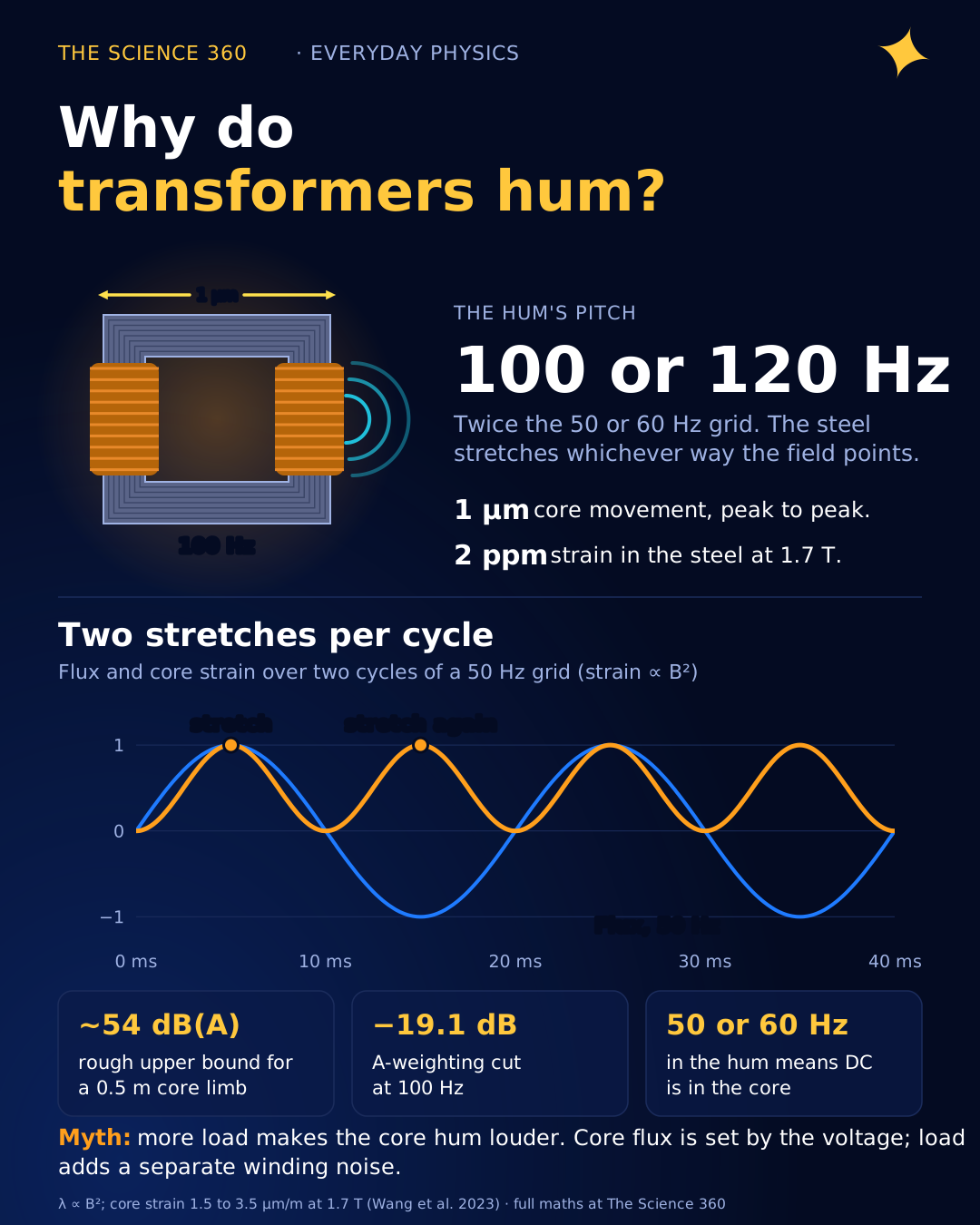
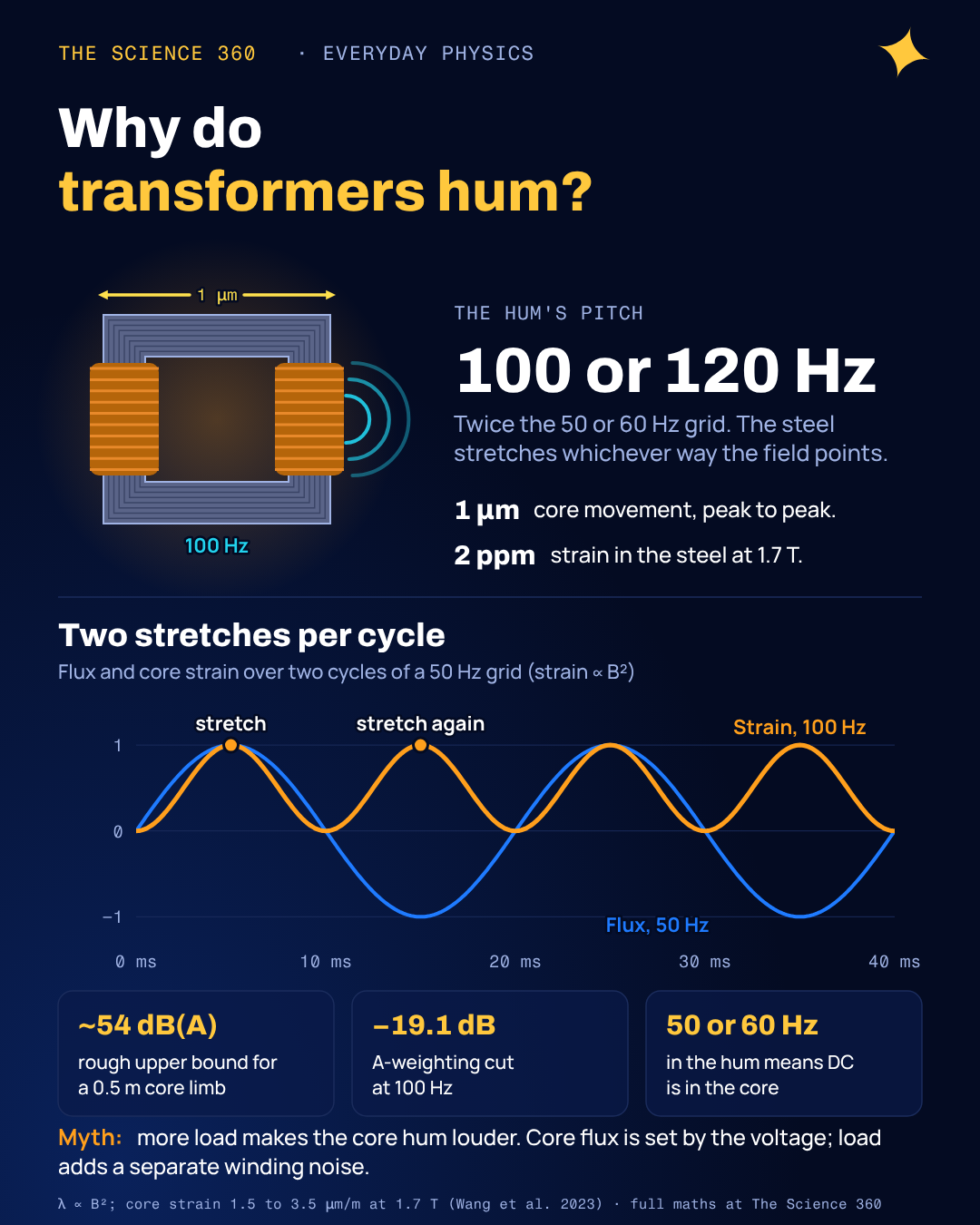
Stand next to a pole transformer in the US and sing the note you hear. If your pitch is good you will land almost exactly halfway between the low B-flat and B a baritone sings (116.5 and 123.5 Hz), at roughly 120 Hz. Do the same next to one in Britain and you will be a little sharp of the G below that (98 Hz), at about 100 Hz. The US grid runs at 60 Hz and the British grid at 50 Hz, so the hum is not at the line frequency. It is at exactly twice it.
That factor of two is the clue to what is going on, and it is the part most explanations skip. The steel core of a transformer physically changes length with magnetisation, by about two millionths of its size, and it does not care which way the field points. So it stretches twice per electrical cycle.
What is magnetostriction?
James Joule noticed in 1842 that an iron bar changes length when you magnetise it. The reason is the material's magnetic domains: small regions in which the atomic magnetic moments all point the same way. In an unmagnetised piece of steel the domains point in many directions. Apply a field and the domains swing round and grow to line up with it, and because the crystal lattice is slightly distorted along each domain's magnetisation direction, the whole piece changes shape.
The size of the effect depends on the material. Cobalt manages about 60 parts per million, the largest of any pure element at room temperature. Engineered alloys such as Terfenol-D reach about 2,000 ppm and are used in sonar and actuators. The grain-oriented silicon steel in power transformers is designed to have very little, and in its rolling direction it does: a 2023 study measuring a laminated core at a peak flux density of 1.7 T found peak-to-peak strains of about 1.5 to 3.5 micrometres per metre, or 1.5 to 3.5 ppm.
Small, but a large transformer core is metres long, and it does this a hundred or more times a second.
Why does a transformer hum at twice the line frequency?
Magnetostrictive strain depends on how strongly the steel is magnetised, not on the direction. A domain magnetised north-to-south distorts the lattice the same way as one magnetised south-to-north. So the strain λ is, to a first approximation, proportional to the square of the flux density B.
The frequency doubling, in one line
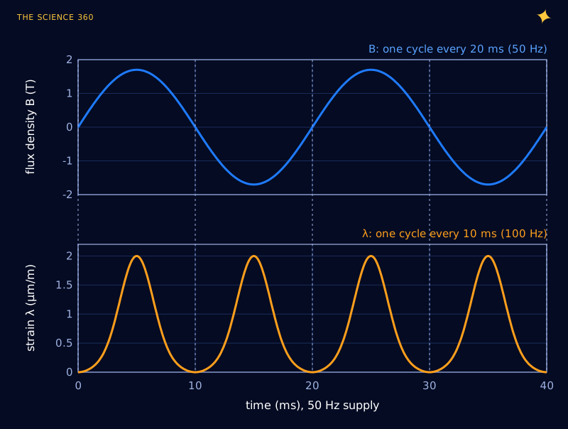
This is a handy diagnostic. On a 50 Hz grid, a transformer that hums at 100 Hz is behaving normally. A strong 50 Hz component means something has broken the symmetry between the positive and negative halves of the cycle, which we come back to below.
How far does the core actually move?
Let us turn the strain into motion and sound, with honest caveats.
Distribution transformer, core limb about 0.5 m long, 1.7 T peak
λpp ≈ 2 μm/m, the middle of the measured 1.5 to 3.5 range:
That is an amplitude of 0.5 μm.
Surface velocity at 100 Hz
Sound pressure if a surface moved like that and radiated perfectly
A-weighted at 100 Hz (−19.1 dB): about 54 dB(A).
That is an upper-bound sketch, not a prediction: real tanks do not radiate perfectly at 100 Hz, and the core's motion reaches the tank through oil, clamps and mounts that can either damp it or amplify it. But it lands in the same range as the NEMA ratings for small liquid-filled distribution transformers, about 56 dB(A) for 45 to 500 kVA units. A motion of half a micrometre, a hundredth of the width of a hair, is enough to be heard across a quiet street.
Where do the harmonics come from?
If strain were exactly proportional to B², you would hear a pure 100 Hz tone. You do not. Transformer hum has a buzzy edge, because the real strain curve is far from a simple square law. Grain-oriented steel's magnetostriction stays small at moderate flux densities and then climbs steeply above about 1.5 to 1.7 T, as small "closure domains" near grain boundaries disappear and the remaining domains are forced to rotate.
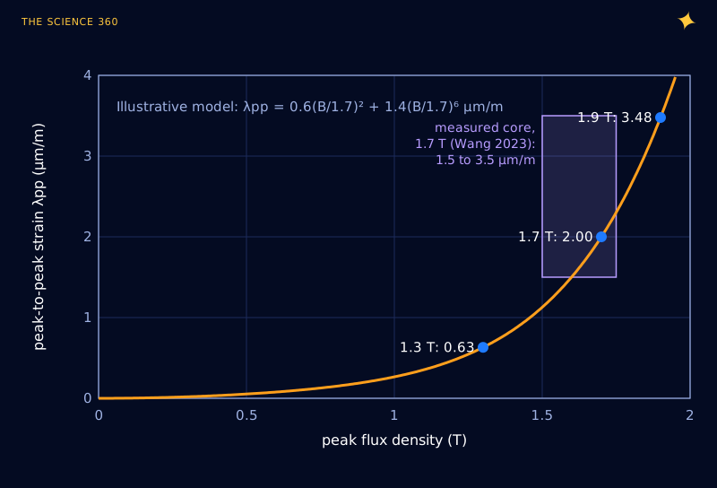
Any curved strain law turns a sine wave of flux into a strain waveform with harmonics. Because strain is still an even function of B, the harmonics land only at even multiples of the line frequency: 100, 200, 300 Hz on a 50 Hz grid. Industry sources report harmonics up to the 16th from cores whose sheets twist and writhe unevenly depending on how they are clamped.
Two further effects decide what you actually hear, and together they push the loudness toward the harmonics.
- Sound tracks acceleration, not displacement. For a vibrating surface small compared with the wavelength (a 100 Hz sound wave is 3.4 m long), the radiated pressure scales with the surface's acceleration, which is (2πf)2 times the displacement. A harmonic at 200 Hz with a quarter of the displacement makes the same acceleration as the 100 Hz fundamental.
- Your ears are deaf to bass. The A-weighting curve, the standard approximation to human loudness perception used in noise regulations, knocks 19.1 dB off a 100 Hz tone but only 10.8 dB off 200 Hz and 7.1 dB off 300 Hz.
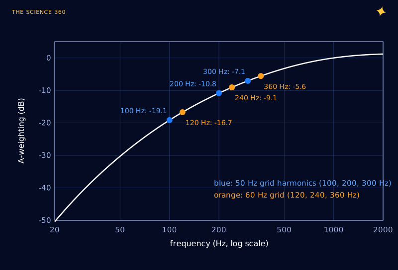
Put the strain model, the acceleration scaling and A-weighting together and you get Figure 4. In this model the 200 Hz harmonic, not the 100 Hz fundamental, dominates the perceived sound at 1.7 T.
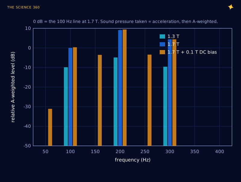
Total A-weighted level from Figure 4 (sum of powers)
At 1.7 T:
At 1.3 T:
Dropping the flux density from 1.7 T to 1.3 T: about 13 dB quieter in this model.
Treat the 13 dB as illustrative, since it depends on the shape of a model curve. The direction is solid, though, and it is the main lever designers have: run the core at a lower flux density. Hammond Power Solutions says the same in plain terms: manufacturers lower the noise by reducing the core flux density. The cost is a bigger, heavier, more expensive core for the same rating.
Does more load make a transformer hum louder?
Here is the misconception most worth correcting. People hear a transformer get louder on a hot afternoon and assume it is straining under the load. For the core hum, that is mostly wrong. The flux density in the core is set by the voltage (, the same equation that decides transformer size), not by the current. A transformer at no load and at full load has nearly the same core flux and nearly the same magnetostrictive hum. Hammond puts it directly: "the sound is related to voltage," and load has "little additional affect." NEMA sound ratings are measured with the transformer energised at no load for this reason.
Load does add a second, separate noise source. The current in the windings sits in the transformer's own leakage magnetic field, so the windings feel Lorentz forces. Force scales with current times field, and the leakage field scales with current, so winding force scales with current squared. That, again, oscillates at twice line frequency. In modern low-noise transformers whose cores are quiet, this load noise can be a large share of the total at full load. So the honest answer is: core hum tracks voltage; winding noise tracks load; both sit at 100 or 120 Hz and its multiples.
If a transformer that has hummed quietly for years suddenly gets louder, the usual suspects are:
- Higher voltage. A few percent overvoltage pushes the flux further up the steep part of Figure 2.
- Loosened clamping. Laminations that are no longer tightly held rattle and buzz, adding higher harmonics.
- A resonance. If the tank, a cover panel or a mounting frame has a natural frequency near 100, 200 or 300 Hz (120, 240, 360 Hz in North America), it can amplify the hum enormously. Designers deliberately keep tank resonances away from these frequencies.
- DC in the core. See the next section.
Why DC current makes transformers louder
A transformer is designed for flux that swings symmetrically between +Bpeak and −Bpeak. Add a small DC current to the winding and the swing shifts: one half-cycle reaches a higher flux than the other, up into the steep part of the strain curve. In the B² picture, contains a cross term , which vibrates at the line frequency itself. Higher terms add 150 Hz, 250 Hz and other odd multiples, which is why Figure 4's DC case grows new orange bars between the normal ones.
The 2023 Sensors study measured this directly in a laminated core: adding DC bias raised the peak-to-peak strain at 1.7 T from 2.19 to 2.58 μm/m, and at a larger DC current the strain at the core limb rose by about 50%. In the real grid, DC gets into transformers from HVDC links with ground return, from some railway systems, and from geomagnetically induced currents during solar storms, when the changing geomagnetic field drives slowly varying currents through long power lines and into transformer neutrals. Large power transformers can become noticeably louder during strong geomagnetic storms, and the extra odd harmonics are a signature of half-cycle saturation.
Hum, buzz and whine: three different sounds
Three related noises get lumped together, and they have different causes:
Transformer hum is the mechanical core and winding vibration described above: 100 or 120 Hz plus even harmonics. A small wall adapter or a microwave oven transformer buzzes more harshly than a large utility unit because cheap cores run close to saturation and their laminations are often loosely held, so they produce strong high harmonics.
Mains hum in audio, the drone in a guitar amp or a bad cable run, is a different animal. It is an electrical signal, usually from a ground loop or magnetic pickup, and it sits at the line frequency itself (50 or 60 Hz). Rectifier "buzz" in a poorly filtered power supply adds harmonics of 100 or 120 Hz on top. If your speaker hums at 60 Hz in North America, it is electrical pickup, not magnetostriction.
Coil whine comes from inductors and transformers in switch-mode power supplies. Their switching frequencies are usually far above hearing, from about 100 kHz to a few MHz, but at light load many controllers switch in bursts that repeat at a few kilohertz, and the magnetics (and ceramic capacitors) sing at that rate. Same physics, magnetostriction and magnetic forces, at a different frequency.
FAQ
What frequency is transformer hum?
The fundamental is twice the line frequency: 100 Hz on a 50 Hz grid and 120 Hz on a 60 Hz grid. Harmonics follow at 200, 300 Hz and so on (or 240, 360 Hz). A component at 50 or 60 Hz itself usually points to something unusual, such as DC bias in the core or a loose part.
Is it normal for a transformer to hum?
Yes. Every iron-core transformer on AC hums because of magnetostriction. Typical distribution transformers are specified at roughly 56 to 68 dB(A) under NEMA standards. A sudden change in the sound, rattling, crackling or popping is not normal and is worth reporting to the utility or an electrician.
Why does a transformer hum louder sometimes?
Core hum depends mainly on the voltage, which sets the flux density in the core, rather than on the load. Higher voltage, DC currents in the grid (for example during geomagnetic storms), loosened clamping or a tank resonance can all make it louder. Heavy load adds a separate winding noise, also at twice line frequency.
Is transformer hum the electricity you can hear?
Not directly. You hear the steel core physically changing length by a few millionths of its size, twice per electrical cycle, and the tank and mounting radiating that vibration as sound. The electricity sets the rhythm, but the sound is mechanical.
Related on The Science 360
Sources
- Wang, Fan, Li, Xu and Yu, "Measurement of Magnetic and Magnetostrictive Characteristics of Transformer Core Based on Triaxial Strain Gauge and B-H Vector Sensor," Sensors 23(13), 5926 (2023), doi:10.3390/s23135926 (λpp 1.5 to 3.5 μm/m at 1.7 T; effect of DC bias; strain at twice excitation frequency): pmc.ncbi.nlm.nih.gov/articles/PMC10346938
- Magnetostriction (Joule 1842; cobalt about 60 ppm; Terfenol-D about 2,000 ppm; transformer hum): en.wikipedia.org/wiki/Magnetostriction
- Hammond Power Solutions, "Why do transformers hum?" (sound related to voltage; load has little additional effect; lower flux density reduces noise): americas.hammondpowersolutions.com FAQ
- Maddox, "Audible sound levels in liquid-filled transformers" (NEMA average sound levels 56 to 68 dB by kVA; measured at no load): maddox.com/resources/articles/audible-sound-levels-in-liquid-filled-transformers
- Transformer Magazine, "Transformer noise" (mechanical frequency twice the electrical frequency; harmonics up to the 16th from lamination writhing): transformer-magazine.com/magazine/transformer-noise
- Applied EE notebook, "Audible noise: whine, hum and buzz" (switch-mode frequencies, burst-mode whine, 60 Hz hum as a sign of asymmetric magnetisation): applied-ee.github.io/ee-notebook
- A-weighting formula (IEC 61672): en.wikipedia.org/wiki/A-weighting
Method note: Figures 1, 2 and 4 use an illustrative strain curve fitted to the middle of published measurements at 1.7 T; the shape above and below that point is a model, not data for a particular steel. Acoustic levels assume radiated pressure proportional to surface acceleration and ignore tank resonances.
Header image: NASA/Sara Lowthian-Hanna (image GRC-2023-C-11347), regraded for this article.