How Does Wireless Charging Work? Coils, Coupling, Heat
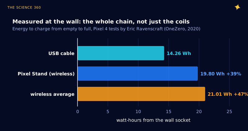
In 2020 Eric Ravenscraft put a power meter between the wall and a Pixel 4 and charged it from empty to full, over and over. By cable it took 14.26 Wh. On wireless pads it averaged 21.01 Wh, 47% more, and Google's own Pixel Stand still needed 19.8 Wh. The usual explanation is that "the magnetic field spreads into the air and is wasted". That explanation is mostly wrong. Two aligned Qi coils can pass more than 90% of the power that reaches them. The losses live in the electronics either side of the coils, and in the misalignment you cannot see.
What is inside a Qi charger and a Qi phone?
The power path in Figure 1 has five stages. A DC supply (5 V for the basic designs) feeds an inverter, a bridge of MOSFETs that chops the DC into a square wave. That drives a series capacitor and the transmitter coil. Across the gap, the phone's receiver coil has its own series capacitor, then a rectifier, then the same charger IC that handles cable charging. Texas Instruments describes the whole thing as "simply an open-cored transformer". The phrase "open-cored" carries most of the physics.
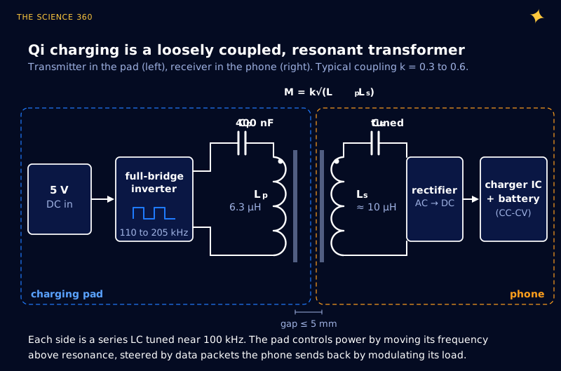
The transmitter coil most cheap pads use is the WPC "A11" type: a flat spiral of stranded wire with a 20.5 mm inner and 44 mm outer dimension on a 50 mm ferrite sheet, 6.3 µH. Superworld's A11 coil lists a DCR of 45 mΩ maximum. TI's bq500212A datasheet says the A11 tank needs "a total capacitance value of 400 nF" to reach 100 kHz, which checks out:
TI recommends making the 400 nF from four 100 nF parts rated for 50 V, with at least one C0G type. The tuning works by the same LC formula covered in the LC resonant frequency post. Power is not regulated by changing voltage: the datasheet says power is regulated "by changing the operating frequency between 110 kHz to 205 kHz. The higher the frequency, the further from resonance and the lower the power."
Why a “loose” transformer is the whole story
In a mains transformer, almost all the flux from one winding passes through the other, because both are wound on one closed iron core. Hold two flat coils a few millimetres apart and only part of the flux links both. The fraction is the coupling coefficient k, and the mutual inductance follows from it:
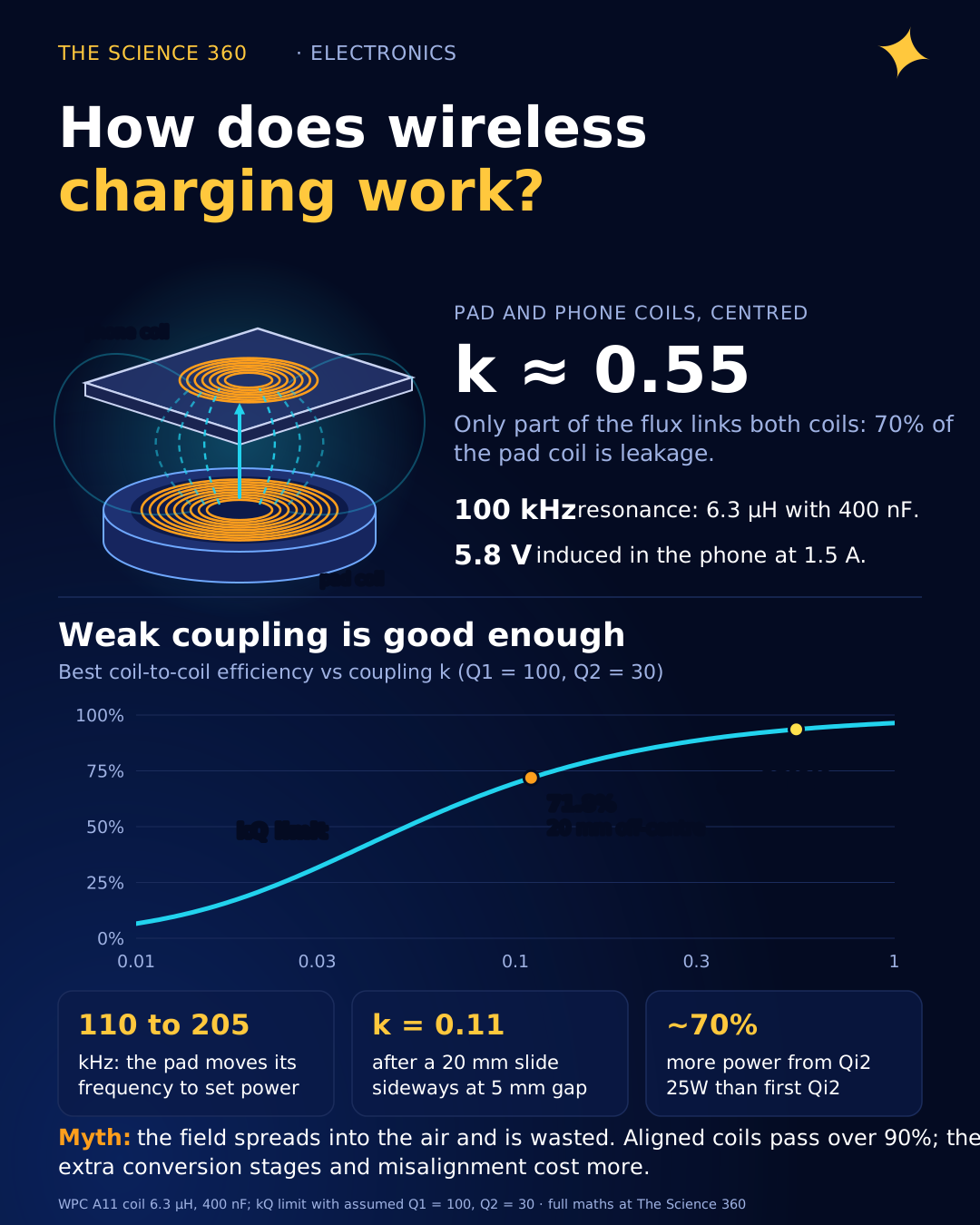
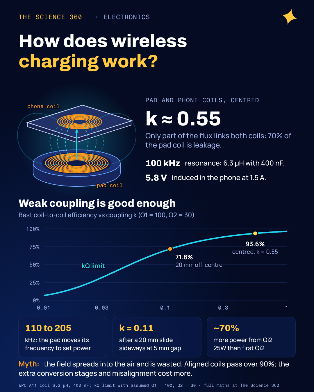
The WPC knowledge base gives k = 0.3 to 0.6 as typical for Qi.
With k = 0.55, Lp = 6.3 µH, Ls = 10 µH:
The voltage induced in the phone coil is . With 1.5 A peak in the pad coil at 140 kHz:
Leakage inductance seen from the pad (secondary shorted), :
That is about 70% of Lp.
That last line is why Qi needs resonance. A transformer with 70% of its inductance as leakage would need a large reactive voltage just to push current through that leakage, and the driver would spend its effort circulating energy instead of delivering it. The series capacitor cancels the reactance of the coil near 100 kHz, so the inverter mostly sees resistance. "Resonant" and "inductive" are not two rival technologies here. Qi is inductive power transfer made workable by resonant tuning.
How fast does coupling fall with distance and misalignment?
We computed k for an A11-size transmitter coil and a phone-size receiver coil by summing the Neumann mutual-inductance integral over every pair of turns, modelling each spiral as concentric rings. The model is air-cored, so absolute values are approximate; ferrite backing raises inductance and tends to raise k. The trends are the point.
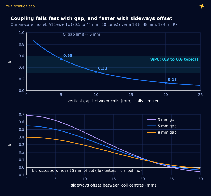
Two things stand out. At the roughly 5 mm gap that TI says the WPC specification allows for, k of about 0.55 matches the top of the WPC's typical range. And sideways offset hurts more than the same vertical distance: at 5 mm gap, a 20 mm slide drops k to about 0.11, roughly what the coils would have at 22 mm straight apart. A phone dropped 2 cm off-centre on a pad is in a much worse place than one lifted by a thick case.
Does weak coupling make wireless charging inefficient?
Less than you would think, if the coils have a good quality factor Q (stored energy per cycle relative to loss; for a coil). Wireless-power papers give the best achievable coil-to-coil efficiency, with the load chosen optimally, as a function of the product :
Pad coil Q1 = 100, phone coil Q2 = 30 (phones have thin, cramped coils).
Centred, k = 0.55:
20 mm off-centre, k = 0.11:
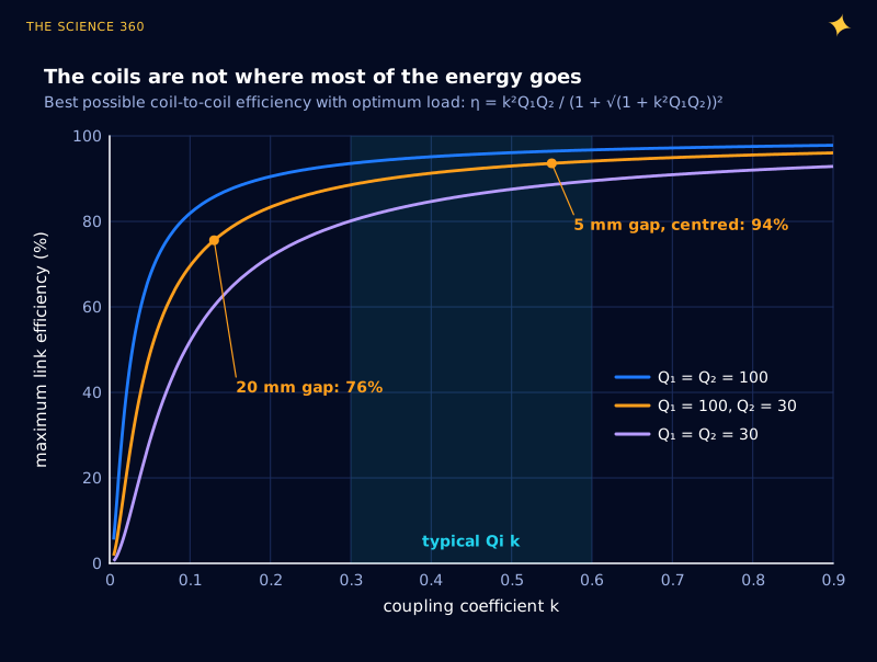
So the coils are not the main culprit in a 47% penalty. A cable charger has one conversion (wall adapter to 5 or 9 V) before the phone's charger IC. A wireless charger keeps that adapter and adds an inverter, two coils and a rectifier. Each stage is good; together they multiply.
Illustrative chain at 15 W into the battery (our numbers, see box below). Inverter, coils, rectifier and charger IC, from pad input to battery:
Loss inside the phone alone (rectifier + charger):
Ravenscraft's measured ratio:
That is, wireless delivered 68% as efficiently as cable.
Why does my phone get hot on a wireless charger?
Because a couple of watts are being dissipated millimetres from the battery, in a sealed glass sandwich with no airflow. The 2.5 W above is in the phone before counting the receiver coil's own copper loss, and at a high-frequency AC current the coil's resistance is above its DC value (see skin effect, which is why Qi coils use many fine strands). Misalignment makes it worse. To keep the same power at lower k, the currents have to rise, and copper loss rises with the square of current.
Lithium cells age faster when warm, so phones throttle charging current as temperature climbs, in the same way they taper near full (see why phone charging slows after 80%). A phone that charges at 15 W on a cool desk and much less under a pillow is not misbehaving; its temperature control is doing its job.
Stray metal is the other heat source. A coin or key on the pad is a shorted single-turn coil, and eddy currents heat it, the same mechanism behind metal sparking in a microwave, at much lower frequency. Chargers guard against it with foreign object detection: the bq500212A monitors the efficiency of the established link (power sent versus power the receiver reports) and stops when too much goes missing.
How does the pad control the power?
The phone is in charge. It measures its rectified voltage and sends packets to the pad by switching a small resistor or capacitor across its coil, which changes the amplitude on the transmitter side. The pad decodes these and moves its frequency. Figure 5 shows why that works, using our circuit model with the A11 values.
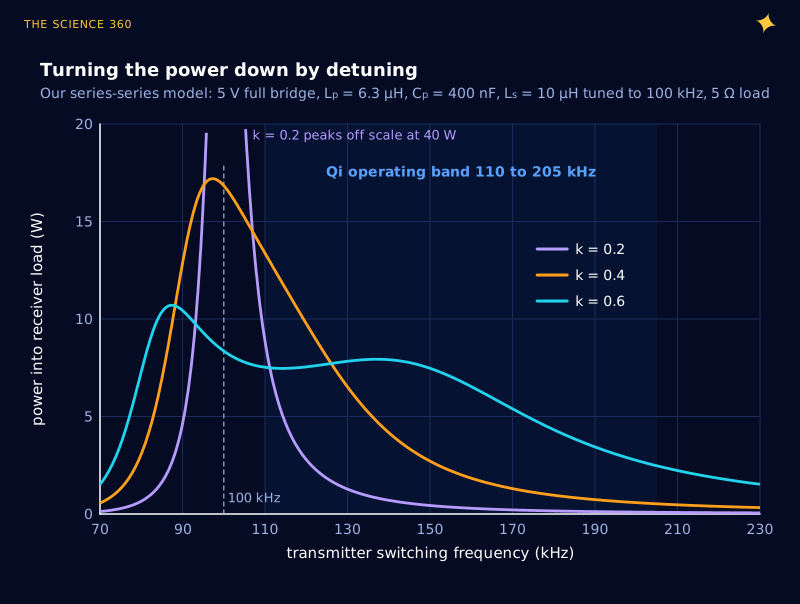
The plot also contains a surprise. At exact resonance, a series-tuned link driven from a voltage source delivers more power when coupling is weaker. With both tanks tuned and small resistances, the receiver current is set by the drive voltage divided by :
Fundamental of a 5 V full bridge, then k = 0.4:
The model, with coil resistance, gives 17 W.
Halve k and the ideal power quadruples.
That is why operating above resonance and letting the receiver report back is essential: without the loop, a phone that slid sideways could be hit with far more power than it asked for. At strong coupling (k = 0.6) the single peak splits in two, the classic frequency splitting of coupled resonators, which is another reason the operating band sits on the high-frequency shoulder.
What do the Qi2 magnets actually do?
They hold the offset in Figure 2 near zero. Qi2 adds a magnetic ring (the Magnetic Power Profile, derived from Apple's MagSafe) so the receiver coil snaps to the centre of the transmitter. The WPC says Qi2 launched in November 2023 at 15 W, and that Qi2 25W (specification v2.2.1), announced on 23 July 2025, "delivers nearly 70% more power than the original Qi2". Faster wireless charging only makes sense if k is kept high and predictable, because every watt of loss in the phone must leave through the glass.
For the cable side of the comparison, USB-C power delivery negotiates its voltage instead of using frequency, and the regulators inside the phone are the same families described in how a buck converter works and how a boost converter works.
FAQ
How does wireless charging work?
A coil in the pad carries alternating current at roughly 100 to 205 kHz, making an alternating magnetic field. Part of that field passes through a coil in the phone and induces a voltage there. Both coils are tuned with capacitors to resonate near 100 kHz. The phone rectifies the voltage to DC and its charger chip charges the battery, while it sends data packets back telling the pad to send more or less power.
How efficient is wireless charging compared with a cable?
In Eric Ravenscraft's 2020 tests with a Pixel 4, a full charge took 14.26 Wh from the wall by cable and 21.01 Wh on average with wireless chargers, about 47% more. The coil-to-coil link itself can exceed 90% when the coils are aligned; most of the extra loss comes from the extra conversion stages and from misalignment.
Why does my phone get hot on a wireless charger?
Several watts are lost as heat at 15 W, and part of that loss sits inside the phone: in the receiver coil, the rectifier and the charger chip, all next to the battery. Poor alignment raises the coil currents and the loss. Phones reduce charging power when the battery gets warm, which is one reason wireless charging often slows down.
Is Qi charging inductive or resonant?
Both. Qi transfers power by magnetic induction, and the transmitter coil is tuned with a series capacitor to resonate at 100 kHz (6.3 µH with 400 nF for the common A11 design). The pad regulates power by operating between 110 and 205 kHz, above resonance.
What do the magnets in Qi2 do?
They hold the phone's receiver coil centred over the transmitter coil. Coupling falls quickly with sideways offset, so keeping the coils aligned keeps coupling high and coil currents and losses low. Qi2 launched in November 2023 at 15 W, and Qi2 25W followed in July 2025.
Related on The Science 360
Sources
- Texas Instruments, bq500212A datasheet SLUSBD6D ("open-cored transformer", resonance fixed at 100 kHz, regulation between 110 and 205 kHz, practical distance under 5 mm, 400 nF tank from 4 × 100 nF at 50 V, FOD by efficiency monitoring): ti.com/lit/ds/symlink/bq500212a.pdf
- Superworld, SCT50036R3KA11S A11 transmitter coil datasheet (6.3 µH, 20.5 mm and 44 mm coil dimensions, 50 mm ferrite, 45 mΩ DCR): Digi-Key hosted PDF
- E. Waffenschmidt, Wireless Power Consortium knowledge base, "Coupling factor" (k typically 0.3 to 0.6, offset reduces k, negative k): wirelesspowerconsortium.com
- E. Waffenschmidt, Wireless Power Consortium knowledge base, "Quality factor" (Q around 100 for mass production): wirelesspowerconsortium.com
- T. Sasatani, A. P. Sample, Y. Kawahara, "Hierarchical resonators for localized charging in room-scale magnetoquasistatic wireless power systems", arXiv:2603.27305 (2026), states the kQ maximum-efficiency expression: arxiv.org/abs/2603.27305
- Wireless Power Consortium, "WPC Ushers in Next Generation of Faster Wireless Charging", 23 July 2025 (Qi v2.2.1, Qi2 25W, nearly 70% more power, Qi2 launched November 2023 at 15 W): wirelesspowerconsortium.com news release PDF
- iPhone in Canada, "Wireless Charging Drastically Less Efficient Than Charging With a Cord" (reports Ravenscraft's 14.26, 21.01 and 19.8 Wh): iphoneincanada.ca; original: OneZero
Method note: Figure 2 sums the Neumann integral numerically over ring pairs (180 points per ring) for air-cored coils; Figure 3 plots the kQ formula; Figure 5 solves the two-mesh series-series circuit at the inverter fundamental. All three are our models, not measurements.
Header image: NASA (image iss066e134729), regraded for this article.