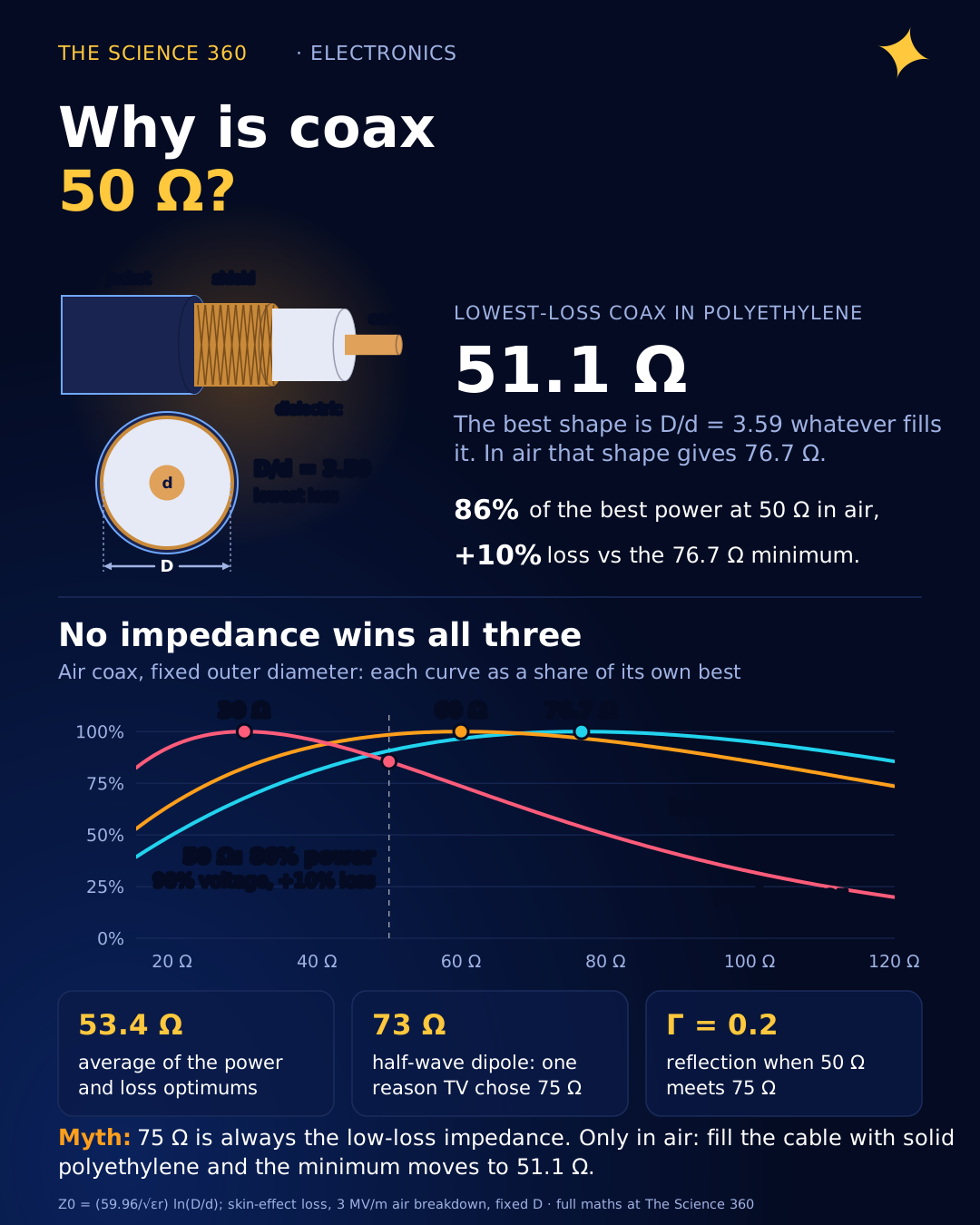
Why Is Coax 50 Ohms? The Loss and Power Math

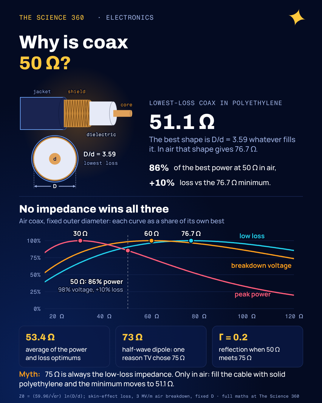
Pick up any piece of lab coax, a BNC lead or the cable behind a Wi-Fi router, and it says 50 Ω. The cable from your TV aerial says 75 Ω. Neither number is a law of nature, and neither is a coincidence. Ask why on a forum and you get one of two answers: "it is a compromise between 30 and 77 ohms" or "it is just a convention". The first is close to the truth but rarely shown, and the second is wrong.
So here is what we will do. Start from the formula for a coaxial line's impedance, write down how loss, power and voltage depend on the geometry, find each optimum with a bit of calculus, and plot all three on one chart. Then we will look at what changes when the cable is filled with plastic instead of air, which is where the usual story gets a twist that most explanations miss.
What sets the impedance of a coax cable?
A coaxial line is a centre conductor of diameter inside a tubular shield of inner diameter , separated by a dielectric with relative permittivity . Its characteristic impedance depends only on the ratio and on :
Length does not appear, and neither does absolute size. A garden-hose-sized hardline and a hair-thin semirigid can both be 50 Ω, as long as the ratio is right. Let us check the formula against a real cable.
Worked example: RG-58/U
Centre conductor d = 0.032 in (0.81 mm); polyethylene dielectric D = 0.116 in (2.95 mm); .
Datasheet value: 53 ± 3 Ω (nominal 53.5 Ω). The stranded RG-58A/U is the 50 Ω version.
Close enough, with the gap down to the exact permittivity of the plastic. Keep that D/d of 3.6 in mind. It will come back.
Where does the 77 Ω loss minimum come from?
At radio frequencies, current flows only in a thin skin on each conductor's surface, so the resistance per metre goes as the inverse of each conductor's circumference. The thin centre conductor dominates. Making d bigger cuts its resistance, but it also pushes the impedance down, and for a given power a lower impedance means more current, which means more I²R loss. Somewhere there is a sweet spot.
For a fixed outer diameter , the conductor attenuation is proportional to divided by . Writing , that becomes
Set the derivative to zero, then solve by iteration starting at :
3.6 → 3.5887 → 3.5918 → 3.5909 → 3.5912 → 3.5911
That is the famous 77 Ω. Notice the minimum is shallow: the curve is flat-bottomed, so a cable anywhere from about 60 to 100 Ω loses only a few percent more than the best possible. That flatness is what makes a compromise cheap.
Why does power handling peak at 30 Ω?
Peak power in an air line is limited by breakdown: when the electric field at the surface of the centre conductor (where it is strongest) exceeds about 3 MV/m, the air ionises and arcs. The field at the inner conductor is , where . So for a given maximum field, the voltage you can apply is , and the power is .
Breakdown voltage alone, , peaks at , giving 60 Ω.
Two different optimums, because voltage and power are different questions. A 30 Ω line carries the most power because its low impedance lets a modest voltage push a lot of current. A 60 Ω line withstands the highest voltage before arcing. To get a feel for the magnitudes:
Worked example: air line with 10 mm shield inner diameter (b = 5 mm), Emax = 3 MV/m
30 Ω: , mm
50 Ω: , mm
77 Ω: a = 1.39 mm, Vmax = 5,340 V, P ≈ 186 kW
These are theoretical peak figures for a perfectly smooth line at sea level. Real ratings sit far lower because of safety margin, connectors, and the fact that average power is limited by heating the centre conductor, not by arcing. The ratios are what matter: going from 30 to 50 Ω costs 14% of peak power, while going on to 77 Ω costs 46%.
Plotting all three: why 50 Ω is a good compromise
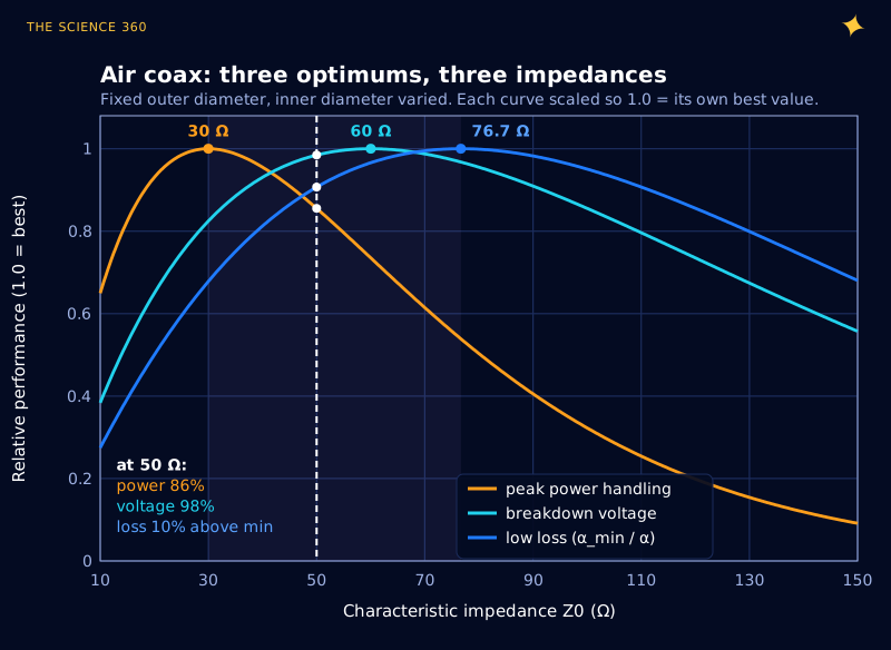
Figure 2 is the whole argument in one picture. No impedance wins all three contests, but 50 Ω never does badly:
| Z0 (air) | Peak power vs best | Breakdown voltage vs best | Loss vs minimum |
|---|---|---|---|
| 30 Ω | 100% | 83% | +47% |
| 50 Ω | 86% | 98% | +10% |
| 60 Ω | 74% | 100% | +3.5% |
| 76.7 Ω | 54% | 97% | 0% |
The often-quoted shortcut is to average the power and loss optimums. The arithmetic mean of 30 and 76.7 is 53.4 Ω; the geometric mean (the natural average for a logarithmic quantity) is 48 Ω. Microwaves101 makes exactly this point and calls 50 Ω "a great compromise between power handling and low loss, for air-dielectric coax". A round number between 48 and 53 is hard to argue with.
The polyethylene twist: 50 Ω is the low-loss choice
Here is the part most explanations skip, and it corrects a widespread misconception: that 75 Ω is always the "low-loss" impedance and 50 Ω always gives up some loss for power. That is only true for air.
The loss optimum is a geometric fact: , whatever fills the space. (The dielectric's own loss depends on its loss tangent and frequency, not on , so it does not move the optimum.) But the impedance that geometry produces depends on . Fill the cable with solid polyethylene, , and the minimum-loss impedance drops by .
Minimum-loss impedance for each dielectric (D/d = 3.591, ln = 1.2785)
Air has , foam PTFE about 1.43 and solid polyethylene 2.25.
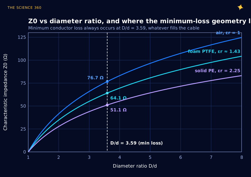
So for the most common flexible cables of the mid-twentieth century, solid PE types like RG-58 and RG-213, 50 Ω is not a compromise on loss at all. It is, within a percent or two, the lowest-loss impedance you can build. Remember RG-58/U's ratio of 3.625: almost exactly the 3.59 optimum. The power and voltage optimums also slide down by the same factor of 1.5 (to 20 Ω and 40 Ω), so in a PE cable 50 Ω trades a little power handling for the best loss. Microwaves101 credits this observation to a reader and gives the same 51.2 Ω figure for PE.
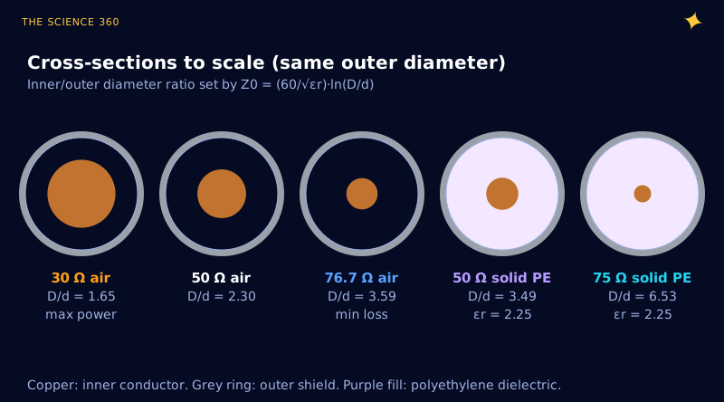
The flip side is that a solid-PE 75 Ω cable has a skinny centre conductor (D/d = 6.5, Figure 1) and is not at its loss minimum. Modern 75 Ω TV cables mostly use foamed dielectric, which pushes the low-loss point back up toward the mid-60s.
What does history actually say?
Here we have to be careful, because this part of the story is repeated more often than it is documented.
What is well established: Lloyd Espenschied and Herman Affel of AT&T and Bell Labs filed for the modern coaxial cable in 1929, and US Patent 1,835,031 ("Concentric Conducting System") was granted on 8 December 1931. Their target was wideband long-distance telephony.
What is widely claimed: that Bell Labs experiments in 1929 found 30 Ω best for power, 60 Ω for voltage and 77 Ω for low attenuation, and settled on a compromise. Belden, DigiKey and others repeat this, and the physics above shows those three numbers are real. Whether a specific 1929 experiment produced them and led to a specific decision is harder to pin down. On the time-nuts mailing list in 2007, John Day questioned whether the figures had been taken out of context, then pointed to a 1934 Bell System Technical Journal paper by Espenschied and Strieby on coaxial systems as the likely origin, while admitting he could not check it. Microwaves101 traces the 50 Ω standard to coax for kilowatt radio transmitters in the 1930s. Another often-told explanation is that early air lines built from standard copper pipe and rod sizes happened to land near 51.5 or 52 Ω. We could not find a primary source for that one, so treat it as plausible folklore.
Our honest summary: the physical trade-off is solid and fully explains why 50 Ω is a sensible choice. The precise historical path, who first picked exactly 50 and when, is less well documented than the internet suggests.
Why does TV use 75 Ω?
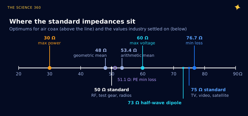
Receive and video systems move microwatts, not kilowatts. Power handling is irrelevant, and every decibel of cable loss comes straight off the signal-to-noise ratio, so the impedance drifts up toward the loss minimum. Three more things nudged it to 75 specifically:
- The dipole. An ideal half-wave dipole in free space has a radiation resistance of about 73 Ω, so 75 Ω cable can feed one directly with very little mismatch.
- Twin lead. Classic TV antennas used 300 Ω folded dipoles and twin lead. A 4:1 balun turns 300 Ω into exactly 75 Ω.
- Flexibility. Microwaves101 suggests 75 Ω was partly a compromise between loss and a thinner, more flexible centre conductor, which matters when you run cable around a house.
Thinking in impedance rather than in "values" is also why we plot impedance against frequency when choosing a 100 nF decoupling capacitor, and why a microwave oven's magnetron feeds its cavity through a matched waveguide (see do microwaves resonate with water?).
Does it matter if you mix 50 Ω and 75 Ω?
Less than people fear for receiving, more than people hope for transmitting. The mismatch reflection coefficient is easy to compute:
Γ² is the fraction of power reflected.
For a short receive cable, 0.18 dB is nothing. For a transmitter whose output stage expects 50 Ω, a 1.5:1 VSWR may trigger power foldback, and in a precision measurement setup the reflection will show up as ripple across frequency. The rule is simple: match the system you are connecting to.
FAQ
Why is coax 50 ohms?
For air-filled coax of a fixed outer size, conductor loss is lowest at about 77 ohms, peak power handling is highest at 30 ohms and breakdown voltage is highest at 60 ohms. 50 ohms keeps about 86% of the best power, 98% of the best voltage and has only about 10% more loss than the minimum, so it is a good all-round compromise for transmitters.
Why is TV coax 75 ohms instead of 50?
Receive and video cables carry tiny signals, so low loss matters more than power handling, which pushes the impedance up toward the 77 ohm low-loss point. 75 ohms is also close to the 73 ohm impedance of a half-wave dipole and is easy to reach from 300 ohm twin lead with a 4:1 balun.
Can I use 75 ohm cable instead of 50 ohm?
For a short receive-only run it often works with little penalty: the mismatch from 75 to 50 ohms reflects 4% of the power (VSWR 1.5). For transmitters, long runs, test equipment or anything where reflections and accuracy matter, use the impedance the system was designed for.
What determines the impedance of a coaxial cable?
Only the ratio of the shield's inner diameter D to the centre conductor's diameter d, and the dielectric constant of the insulation: ohms. Length does not change it, and neither does overall size if the ratio stays the same.
Sources
- Microwaves101, "Why fifty ohms?" (loss minimum near 77 Ω, power at 30 Ω, PE minimum at 51.2 Ω, 75 Ω discussion). microwaves101.com
- DigiKey, "The Reasons for 50 Ω and 75 Ω Transmission Lines, And Why You Should Choose Carefully". digikey.com
- Belden, "50 Ohms: The Forgotten Impedance". belden.com
- John Day, "[time-nuts] 50 vs 75 ohm cables", time-nuts mailing list, May 2007. febo.com
- Herman Affel biography (US Patent 1,835,031 with Lloyd Espenschied). wikipedia.org; National Inventors Hall of Fame, Lloyd Espenschied. invent.org
- Caledonian Cables, RG58 MIL-C-17 datasheet (0.80 mm conductor, 2.95 mm PE, 53 ± 3 Ω). caledonian-cables.com
- University of Toronto ECE422 notes, "The half-wave dipole" (73 Ω radiation resistance). utoronto.ca
- American Meteorological Society Glossary, "Dielectric strength" (about 3 × 10⁶ V/m for dry air at sea level). ametsoc.org
Header image: NASA/JPL-Caltech (image PIA25136), regraded for this article.