UART Baud Rate Error Tolerance: The Real Budget
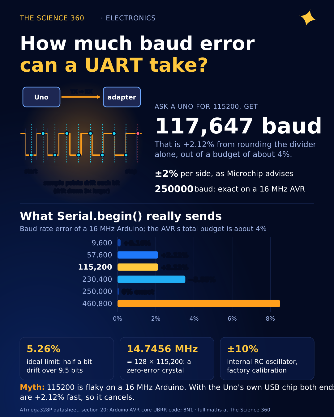
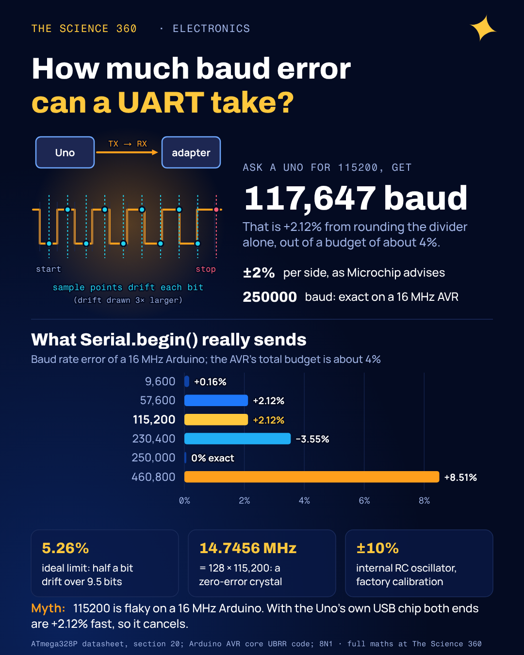
Type Serial.begin(115200) on a 16 MHz Arduino and the chip does not send 115,200 bits per second. It sends 117,647. The 16 MHz clock simply does not divide into 115,200 evenly, so the hardware picks the nearest divider it can and you are 2.12% fast before anything else goes wrong. Most of the time it works anyway. Sometimes, with a different USB adapter, a 3.3 V board or a faster baud rate, it produces garbage, and the reason is a budget of only about 4 to 5 percent shared between both ends of the wire.
Page one mixes a Microchip help page that gives no number at all, STM32 reference-manual tables, and forum threads quoting "5%" or "2%" without saying whether that is per side or total. None of them show what Arduino's own code chooses, why the Uno's USB chip hides its error, or why 230400 is a trap. This post derives the tolerance, then spends it on real boards.
Why does a UART have a baud rate tolerance at all?
An asynchronous serial line has no clock wire. The receiver sees only the falling edge of the start bit and then times every following bit with its own clock. If the two clocks disagree, the receiver's sampling points drift through the frame, a little more with each bit. Resynchronisation happens only at the next start bit.
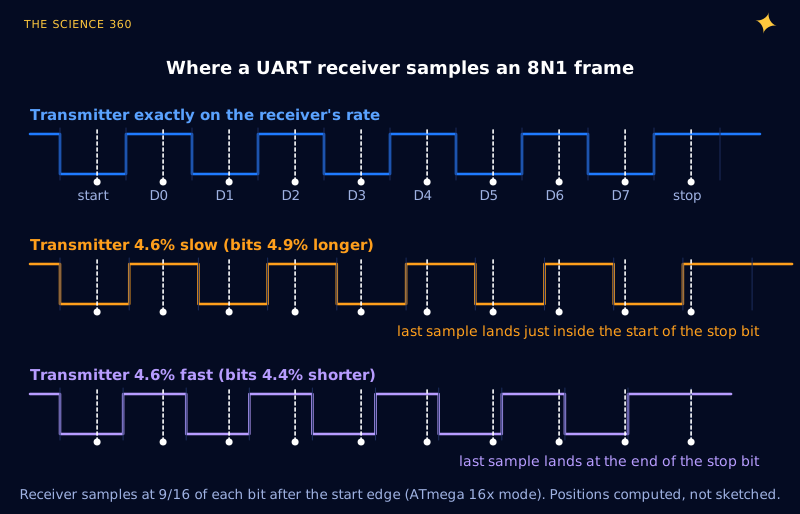
For the classic 8N1 frame (one start bit, eight data bits, no parity, one stop bit) the last thing the receiver samples is the stop bit, whose centre sits 9.5 bit times after the start edge. The sample can drift by at most half a bit before it lands in the wrong bit. That gives the ideal limit:
Ideal receiver, single sample at the centre of each bit:
total mismatch (8N1). General, with :
Figure 1 shows the drift on a real frame. The receiver's sample points (black) are computed from the ATmega328P's 16x timing; the transmitted waveforms are drawn at exactly the receiver's rate and at the two extremes the chip can survive.
Where the 4.5% figure comes from
A real UART does worse than the ideal 5.26% for two reasons, both described in section 20.8 of the ATmega328P datasheet. First, it does not see the start edge exactly. In Normal mode it samples the line 16 times per bit (8 times in Double Speed mode), so it only knows when the start bit began to within one sample, 1/16 of a bit. Second, it decides each bit by majority vote of three samples, numbers 8, 9 and 10 of the 16, which acts as a small noise filter but moves the decision window slightly away from the exact centre.
Microchip packs both effects into two formulas, where S is samples per bit, SF the first voting sample and SM the middle one:
Normal mode, 8N1:
Double Speed (U2X), 8N1:
These match the datasheet's Tables 20-2 and 20-3 (Rslow 95.36%, Rfast 104.58%; and 96.00%, 103.90%), with one small oddity: the normal-mode table prints the total as −4.54%, while its own Rslow of 95.36% works out to −4.64%. Either way, the "about 4.5%" rule of thumb is the normal-mode figure, and it shrinks with longer frames and with fewer samples per bit, as Figure 2 shows.
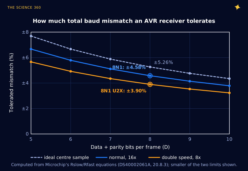
The key word is total. The 4.6% is the ratio between the transmitter's rate and the receiver's rate. Both ends contribute, so Microchip's tables recommend that each side keep its own error within about half: ±2.0% for 8N1 in Normal mode and ±1.5% in Double Speed mode, "under the assumption that the Receiver and Transmitter equally divides the maximum total error."
How the baud rate divider rounds: UBRR
An AVR generates its baud rate by dividing the system clock with a 12-bit register, UBRR:
Normal mode (U2X = 0):
Double Speed (U2X = 1):
UBRR must be a whole number, so unless fOSC happens to be a multiple of (or ), the result is off. The worked case everyone hits:
16 MHz, 115,200 baud, Normal mode:
16 MHz, 115,200 baud, Double Speed:
Here is the trade that makes U2X interesting. Normal mode has the bigger tolerance (−4.64%) but the bigger error (−3.55%), using 77% of the budget on rounding alone. Double Speed has a smaller tolerance (+3.90%) but a smaller error (+2.12%), using 54%. Double Speed wins at 115200, which is why Arduino uses it.
What does Serial.begin() actually pick?
The AVR Arduino core computes the divider in HardwareSerial::begin(). It tries Double Speed first with baud_setting = (F_CPU/4/baud-1)/2, integer arithmetic that rounds to the nearest UBRR. It falls back to Normal mode only if the value would exceed 4095, or in one hard-coded case: 57600 baud on a 16 MHz board, kept in Normal mode "for compatibility with the bootloader shipped with the Duemilanove and previous boards and the firmware on the 8U2 on the Uno and Mega 2560." Figure 3 runs that code for every common rate.
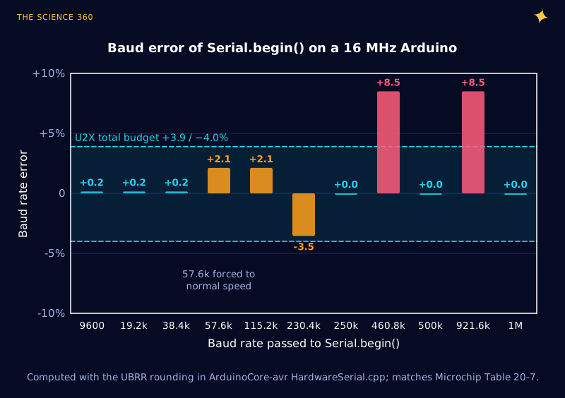
Three things stand out. The 57600 special case costs accuracy: Normal mode gives UBRR 16 and 58,824 baud (+2.12%), while Double Speed would have given UBRR 34 and 57,143 baud (−0.79%). The "odd" rates 250000, 500000 and 1000000 are perfect on a 16 MHz board because exactly. And 460800 and 921600 are hopeless at +8.5%, more than twice the budget.
Why 115200 works with the Serial Monitor but not with your adapter
This is the misconception worth correcting. A widespread explanation for flaky serial says "115200 is 2.1% off on a 16 MHz Arduino, so it is unreliable". It is 2.1% off. Whether that matters depends entirely on the other end.
On an Uno R3, the USB to serial converter is a second AVR, an ATmega16U2, also clocked at 16 MHz. Its firmware (Arduino-usbserial, built on LUFA) sets its own UART with the macro ((F_CPU / 8) + (Baud / 2)) / Baud − 1 in Double Speed mode, and also special-cases 57600 to Normal mode. At 115200 that gives:
16U2:
U2X → 117,647 baud (+2.12%)
ATmega328P: UBRR 16, U2X → 117,647 baud (+2.12%)
Mismatch from rounding:
Both ends are wrong by the same amount, so the mismatch the receiver sees is only the difference between the two oscillators. The PC never notices: the 16U2 talks to it over USB, where baud rate has no physical meaning.
Swap in an adapter that produces the requested rate exactly, or another microcontroller with a fractional baud generator, and the full 2.12% appears. Add the clock tolerance of each end and the budget looks like Figure 4.
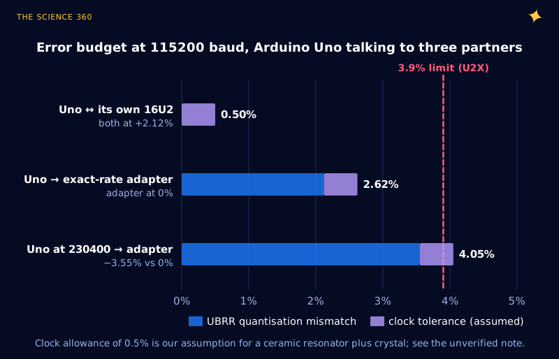
Uno → exact adapter at 115200:
Works, 1.3 points spare.
Uno → exact adapter at 230400, Arduino rounding:
against a −4.00% limit → fails at the edge
So the same sketch that is rock solid at 230400 with the Serial Monitor can drop characters through an FTDI cable, and the cure is not a better cable but a better baud rate: 250000 is exact on both an AVR and most adapters that support arbitrary rates.
Why 14.7456 MHz and 11.0592 MHz crystals exist
If rounding is the problem, choose a clock that does not need rounding. Every standard rate from 300 to 115,200 baud divides into evenly, so any crystal that is a whole multiple of 1.8432 MHz gives exact baud rates. The familiar "UART crystals" are exactly that:
(the original 8250/16550 UART clock)
(11.0592 MHz is also for 8051 timers)
Figure 5 sweeps the clock from 1 to 20 MHz and shows how special those frequencies are. Between them the error swings up and down as UBRR steps, with peaks of several percent. The 16 MHz everyone uses sits at 3.5% in Normal mode; 20 MHz, another common AVR clock, manages 1.4%.
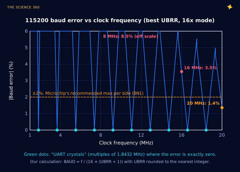
The price of a UART crystal is everything else. A 14.7456 MHz clock makes millisecond timers awkward (14,745.6 cycles per millisecond) and runs a little below the 16 MHz many libraries assume. That is why Arduino chose 16 MHz and lives with 2.12%. For a design where the UART matters more than round timer numbers, such as a data logger or a Modbus node, the crystal choice is worth making, and the load capacitors are sized as in the crystal load capacitor calculation. The same divide-down logic, applied to timekeeping instead of baud rates, is why watch crystals run at 32,768 Hz.
3.3 V boards, 8 MHz and the internal oscillator
The 3.3 V Pro Mini and similar boards run at 8 MHz, and there 115200 is genuinely bad:
8 MHz, Arduino rounding:
against a −4.00% limit. Normal mode would be worse: UBRR 3 → 125,000 baud, +8.5%.
That leaves under half a percent for both clocks combined. At 8 MHz, 57600 (U2X, UBRR 16, +2.12%) or 38400 (+0.16%) are the sensible choices.
Running from the internal RC oscillator is worse again. The ATmega328P datasheet gives its factory calibration accuracy as ±10% at 3 V and 25 °C, and ±1% after user calibration over the full voltage and temperature range. A ±10% clock cannot hold a ±2% per-side budget at any baud rate; even ±1% uses half of it before the divider adds anything. If a design must use the internal oscillator, calibrate it (OSCCAL) against a known reference, or use a protocol that measures the incoming bit time, such as LIN's sync byte.
The voltage level side of mixing 3.3 V and 5 V UARTs is a separate problem, covered in 3.3 V to 5 V level shifting. Edge speed matters little here: even a slow 200 ns edge is 2% of a bit at 115200.
A worked design check
Suppose a 16 MHz ATmega328P must talk at 115200 baud, 8N1, to an ESP32. Assume the ESP32's divider is close to exact and its crystal is good to 0.01%; both are typical but you should check your part.
AVR divider error (U2X, UBRR 16): +2.12%
AVR clock: crystal ±0.01% (or resonator, assume ±0.5%)
ESP32 divider + clock: assume ±0.1%
Worst-case total:
AVR receiving (U2X limit +3.90%): margin 1.18 points
ESP32 receiving: depends on its sampling, but a 16x receiver gives about ±4.6% → margin about 1.9 points
Verdict: works. Switch the AVR to 14.7456 MHz, or use 250000 baud, to remove the 2.12% entirely.
To check a link in practice, measure rather than trust the arithmetic. Send a stream of 0x55 ('U'), which alternates 0 and 1 and produces a square wave at half the baud rate, and measure the period with a scope or frequency counter; a correctly compensated probe (see how a 10x oscilloscope probe works) is plenty at these speeds. At 117,647 baud the square wave is 58.8 kHz instead of 57.6 kHz, a difference any counter shows at once.
The sampling ideas here, a fixed number of samples per bit and a vote among them, are a small cousin of the sampling theory in the Nyquist theorem: the receiver needs enough samples to locate the edge, and every sample of uncertainty comes out of the timing budget.
FAQ
How much baud rate error can a UART tolerate?
For an 8N1 frame, an ideal receiver that samples once in the middle of each bit tolerates 5.26% total mismatch. A real ATmega328P receiver tolerates about +4.6% and −4.6% in 16x mode and +3.9% and −4.0% in 8x double speed mode. That is the total between transmitter and receiver, so each side should stay within roughly half of it: Microchip recommends 2.0% and 1.5% respectively.
What is the baud rate error for 115200 on a 16 MHz Arduino?
Arduino's Serial.begin(115200) uses double speed mode with , giving baud, which is 2.12% fast. In normal mode the best setting is , giving 111,111 baud, 3.55% slow.
Why are 14.7456 MHz and 11.0592 MHz crystals used?
They are integer multiples of 1.8432 MHz, which is 16 times 115,200. Divided by 16 times a whole number they give standard baud rates exactly, so the UART divider adds zero error. 14.7456 MHz is 128 times 115,200, so gives exactly 115,200 baud.
Why does serial work with the Arduino Serial Monitor but not with my USB adapter?
On an Uno R3 the USB-serial chip is an ATmega16U2 also running at 16 MHz with the same divider, so both ends are 2.12% fast at 115200 and the mismatch cancels. An adapter that produces the exact baud rate sees the full 2.12% error, and at 230400 the Arduino is 3.55% slow, close to the 4% double-speed limit.
Related on The Science 360
Sources
- Microchip, ATmega48A/PA/88A/PA/168A/PA/328/P datasheet DS40002061A, section 20 (BAUD and UBRR equations, start bit detection, majority voting of samples 8, 9, 10, Rslow/Rfast equations, Tables 20-2 and 20-3, resonator warning, Table 20-7 UBRR examples at 14.7456 and 16 MHz) and Table 29-9 (internal RC oscillator ±10% factory, ±1% user calibration): microchip.com DS40002061A
- Arduino, ArduinoCore-avr
HardwareSerial.cpp,HardwareSerial::begin()(U2X first, 57600 exception, UBRR formula): github.com/arduino/ArduinoCore-avr - Arduino, Arduino-usbserial firmware for the ATmega8U2/16U2 (57600 special case, SERIAL_2X_UBBRVAL in Double Speed mode): github.com/arduino/ArduinoCore-avr firmwares
- Dean Camera, LUFA
Serial_AVR8.h(SERIAL_UBBRVAL and SERIAL_2X_UBBRVAL rounding macros): github.com/abcminiuser/lufa - Microchip online documentation, "Baud Rate Tolerance" (page-one example; describes the total-error concept but gives no figures): onlinedocs.microchip.com
Method note: Figures 1 to 5 are computed by us from the datasheet equations and the Arduino core's integer arithmetic. The 0.5% clock allowance and the ESP32 figures in the worked design check are stated assumptions, not datasheet values.
Header image: NASA/Ken Ulbrich (image AFRC2020-0038-38), regraded for this article.