How do you calculate the frequency of a 555 astable?
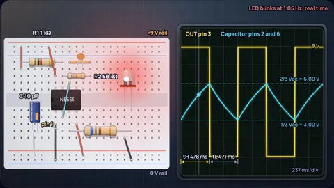
Add R1 to twice R2, multiply by C, and divide 1.44 by the result. A 555 astable runs at f = 1.44 ÷ ((R1 + 2R2) × C), with the output high for 0.693 (R1 + R2) C and low for 0.693 R2 C. With R1 = 1 kΩ, R2 = 68 kΩ and C = 10 µF that is 1.05 Hz: the LED is on for 478 ms and off for 471 ms, a duty cycle of 50.4%. The supply voltage does not appear anywhere in the formula.
The simulation uses those datasheet equations from Texas Instruments' NE555 data sheet and draws everything they imply: the circuit on a breadboard or as a schematic, a labelled pinout with live pin states, and a two-channel scope. Switch the mode to Frequency → parts and it works backwards, picking an E6 capacitor and E12 resistors that land closest to the frequency and duty you type in. The derivation of 0.693 and 1.44 is in where the 555 formula comes from; this page is about using it.
Key results from the simulation
- f = 1.44 ÷ ((R1 + 2R2) C): 1 kΩ, 6.8 kΩ and 100 nF give 988 Hz. Swap the capacitor for 10 µF and 68 kΩ for R2 and you get 1.05 Hz, a classic LED flasher.
- The capacitor lives between 1/3 and 2/3 Vcc: at 9 V it bounces between 3 V and 6 V. Change Vcc on the slider and both levels move, but the timing does not, because the charging current scales with the supply too.
- Duty is always above 50%: the high time uses R1 + R2 and the low time only R2. Equal resistors give 66.7%; R2 = 68 R1 gives 50.4%. Getting below 50% needs a diode across R2 or a different circuit.
- The first pulse is long: from a dead start the capacitor charges from 0 V, not 1/3 Vcc, so the first high time is 1.1 (R1 + R2) C. For the flasher that is 758 ms instead of 478 ms.
- R1 costs current: while the output is low, pin 7 grounds the bottom of R1, so Vcc ÷ R1 flows for nothing. With 1 kΩ on 9 V that is 9 mA. Bigger R1, smaller waste.
Six 555 circuits worth building
Each card gives the parts, the frequency and duty the datasheet formulas predict, and a button that loads the circuit into the simulator. Real parts land within a few percent, mostly because capacitors are rarely closer than 10% to their marked value.
The 1 Hz LED flasher
R1 1 kΩ · R2 68 kΩ · C 10 microfaradThis is the first 555 circuit most people build. The output is high for 478 ms and low for 471 ms, so the LED blinks at 1.05 Hz with an almost even 50.4% duty. R2 is 68 times R1, which is what pulls the duty close to 50%.
Watch the breadboard view: the timing capacitor's level bar rises while the LED is on and falls while it is off, and the scope cursor runs in real time. The cyan jumper over the chip ties pin 6 to pin 2, which is what turns a one-shot timer into an oscillator. The first flash after power-up lasts 758 ms.
Related reading: Build it pin by pin
A 1 kHz clock from 1 kΩ, 6.8 kΩ and 100 nF
R1 1 kΩ · R2 6.8 kΩ · C 100 nFR1 + 2R2 = 14.6 kΩ, so f = 1.44 ÷ (14.6 kΩ × 100 nF) = 988 Hz. The high time is 541 µs and the low time 471 µs, a duty of 53.4%. That is close enough to 1 kHz for a test tone or a clock for a counter chip.
At this speed the LED flickers far faster than the eye can follow, so the simulator draws it steady at the average brightness and slows the scope sweep down so you can see the shape. On 5 V the 1 kΩ R1 wastes 5 mA whenever the output is low; if that matters, scale both resistors up ten times and use 10 nF.
Related reading: Why the constant is 1.44
Long on, short off: making R1 the big one
R1 100 kΩ · R2 10 kΩ · C 10 microfaradMake R1 much larger than R2 and the charge takes much longer than the discharge. Here the output stays high for 762 ms and drops for only 69.3 ms: 91.7% duty at 1.2 Hz. The LED looks like it is on with a brief wink.
The opposite, a short flash and a long gap, is what people usually want for a beacon, and the plain astable cannot do it. Either drive the LED from the inverted output (an LED from Vcc to pin 3 lights while the output is low), or add a diode across R2 so the capacitor charges through R1 only.
Design a 440 Hz tone with standard parts
Frequency → parts modeType 440 Hz and 55% duty and the calculator tries every E6 capacitor, solves R1 = (2D − 1) ÷ (0.693 f C) and R2 = (1 − D) ÷ (0.693 f C), rounds both to E12 and keeps the set that lands closest. It picks R1 = 4.7 kΩ, R2 = 22 kΩ and C = 68 nF, which gives 436 Hz at 54.8% duty.
436 Hz is 1.0% flat of concert A, about the error you would get from the capacitor tolerance anyway. For an in-tune note, put a 4.7 kΩ trimmer in series with R2 and adjust by ear or with a tuner app. A small speaker needs a series capacitor and resistor; the NE555 output can source up to 200 mA, more than a little speaker needs.
A 2 Hz blinker that is on three quarters of the time
Frequency → parts modeFor 2 Hz at 75% duty the high time is 0.375 s and the low time 0.125 s. The calculator lands on R1 = 56 kΩ, R2 = 27 kΩ and C = 6.8 µF, which gives 1.93 Hz at 75.5%. The exact values it wanted were 53.1 kΩ and 26.5 kΩ; E12 rounding costs 3.5% in frequency.
This is a good place to see that the duty slider has a floor. Drag the target toward 51% and R1 shrinks toward its 1 kΩ minimum. Below 1 kΩ the discharge transistor would carry a large current every cycle, so the calculator pins R1 there and warns you.
A 38 kHz carrier for an infrared remote
Frequency → parts modeTV remotes flash their IR LED at a carrier near 38 kHz so the receiver can ignore sunlight and lamps. The calculator suggests R1 = 3.9 kΩ, R2 = 18 kΩ and C = 1 nF, which gives 36.2 kHz, 4.8% low. IR receiver modules have a band-pass filter only a few kHz wide, so that error matters: trim R2 or use E24 parts.
At 38 kHz the NE555 is still well inside TI's suggested 100 kHz ceiling. Small timing capacitors are where stray capacitance on a breadboard (a few pF per row) starts to shift the frequency, so expect to trim on the real circuit.
555 astable values for common circuits
| Circuit | R1 | R2 | C | Frequency | High time | Low time | Duty |
|---|---|---|---|---|---|---|---|
| Slow LED flasher | 1 kΩ | 68 kΩ | 10 µF | 1.05 Hz | 478 ms | 471 ms | 50.4% |
| Even blink, 1 µF | 1 kΩ | 680 kΩ | 1 µF | 1.06 Hz | 472 ms | 471 ms | 50.0% |
| About 1 kHz clock | 1 kΩ | 6.8 kΩ | 100 nF | 988 Hz | 541 µs | 471 µs | 53.4% |
| Equal resistors | 10 kΩ | 10 kΩ | 100 nF | 481 Hz | 1.39 ms | 693 µs | 66.7% |
| Long on, short off | 100 kΩ | 10 kΩ | 10 µF | 1.2 Hz | 762 ms | 69.3 ms | 91.7% |
| Audio tone | 4.7 kΩ | 22 kΩ | 68 nF | 436 Hz | 1.26 ms | 1.04 ms | 54.8% |
| IR remote carrier | 3.9 kΩ | 18 kΩ | 1 nF | 36.2 kHz | 15.2 µs | 12.5 µs | 54.9% |
Values from the NE555 datasheet equations with 0.693 and 1.44. They ignore capacitor tolerance (often ±10 to 20%), the discharge transistor resistance and propagation delays, which matter above a few tens of kilohertz.
How the simulation works
The model is the astable circuit in TI's NE555 datasheet (section 6.3.2). R1 runs from Vcc to the discharge pin 7, R2 from pin 7 to the capacitor, and pins 2 and 6 are tied to the capacitor. While the output is high, pin 7 is open and C charges through R1 + R2 toward Vcc. At 2/3 Vcc the threshold comparator flips the internal flip-flop, pin 3 goes low and pin 7 grounds the R1/R2 node, so C discharges through R2 alone. At 1/3 Vcc the trigger comparator flips it back.
Each half is a slice of an RC exponential where the gap to the target halves, so it takes ln 2 time constants. The datasheet rounds ln 2 to 0.693 and its reciprocal to 1.44, and so does the calculator. The scope traces are drawn from the exact exponentials, so the cyan curve touches the dashed 1/3 and 2/3 lines exactly where the yellow output switches.
For slow circuits (up to 15 Hz) the LED, the pin states and the scope cursor run in real time. Faster than that the LED is drawn steady at its average brightness, which is what your eye sees, and the scope sweep is slowed so it crosses the screen in 1.5 seconds. The note at the top right says which is happening.
Reverse design tries every E6 capacitor from 100 pF to 1000 µF, computes R1 = (2D − 1) ÷ (0.693 f C) and R2 = (1 − D) ÷ (0.693 f C), rounds them to E12, and keeps the set with the smallest combined frequency and duty error, as long as R1 is at least 1 kΩ and R1 + R2 stays under 1 MΩ.
What the model leaves out
- Output voltage: the scope draws the output swinging the full 0 V to Vcc. A bipolar NE555 actually sits about 1.7 V below Vcc when sourcing 100 mA (datasheet typical high level 3.3 V at 5 V), and a little closer at light load.
- Component tolerance: the formula assumes the marked values. Aluminium electrolytic capacitors are commonly ±20%, which moves the frequency by about the same amount. Use film or C0G ceramic for anything that must hold its frequency.
- High frequency effects: propagation delay and the discharge transistor resistance add a little to each half period. TI suggests staying at 100 kHz or below with the NE555; the calculator flags anything above.
- Threshold current: pin 6 draws up to 250 nA, which limits R1 + R2 to about 3.4 MΩ at 5 V according to the datasheet. The calculator warns above that.
- Supply dependence: the model makes timing exactly independent of Vcc. The datasheet gives a small residual sensitivity of about 0.3% per volt in astable mode.
Common misconceptions
“A higher supply voltage makes the 555 faster.” No. Both thresholds come from an internal divider across Vcc, and the charging current also scales with Vcc, so the voltage cancels. Move the supply slider and the frequency readout does not change.
“Equal resistors give a 50% square wave.” No. With R1 = R2 the high time uses 2R and the low time uses R, so the duty is two thirds. The plain astable can approach 50% when R2 is much bigger than R1, but never reach it.
Frequently asked questions
What is the formula for 555 timer frequency?
f = 1.44 ÷ ((R1 + 2R2) × C). The output is high for 0.693 (R1 + R2) C and low for 0.693 R2 C, and the period is the sum, 0.693 (R1 + 2R2) C. With R1 = 1 kΩ, R2 = 6.8 kΩ and C = 100 nF the frequency is 988 Hz.
How do I calculate R1 and R2 for a given frequency and duty cycle?
Pick a capacitor first, then use R2 = (1 − D) ÷ (0.693 f C) and R1 = (2D − 1) ÷ (0.693 f C), where D is the fraction of the period the output is high. For 440 Hz at 55% with 68 nF that gives about 4.82 kΩ and 21.7 kΩ; the nearest E12 values 4.7 kΩ and 22 kΩ give 436 Hz.
Why is the 555 duty cycle always above 50%?
Because the capacitor charges through R1 + R2 but discharges through R2 only, so the high time is always longer than the low time. R1 cannot be zero, or pin 7 would short the supply. Equal resistors give 66.7%. For 50% or less, add a diode across R2 or divide the output by two with a flip-flop.
Does the 555 timer frequency depend on supply voltage?
Almost not at all. The thresholds are 1/3 and 2/3 of Vcc and the charging current is proportional to Vcc, so the voltage cancels. TI lists a residual sensitivity of about 0.3% per volt for the NE555 in astable mode.
What is the maximum frequency of an NE555?
TI recommends 100 kHz or below for the bipolar NE555 to keep the waveform clean, and suggests the CMOS TLC555 for faster work. Above a few tens of kilohertz, internal delays make the real frequency a little lower than the formula.
Why is the first pulse of a 555 astable longer?
At power-up the capacitor starts at 0 V instead of 1/3 Vcc, so it has to charge further to reach 2/3 Vcc. That takes ln 3 ≈ 1.1 time constants instead of ln 2 ≈ 0.693, so the first high time is 1.1 (R1 + R2) C. For the 1 Hz flasher that is 758 ms.
Keep learning
555 Timer Astable Circuit Explained with Waveforms
What each NE555 pin does in an astable circuit, how to read the output and capacitor waveforms, a 1 Hz LED flasher worked through, and the usual faults.

555 Timer Frequency Formula: Where 1.44 Comes From
f = 1.44/((R1 + 2R2)C). Why 1.44 is 1/ln 2, why duty cycle can't drop below 50%, and why the diode fix misses 50% at 5 V. Worked 1 kHz example.

Why Is the RC Time Constant 63%? The Math of 1 − 1/e
63.2% is 1 minus 1/e, the point where an RC curve would have finished if it kept its starting slope. Why e appears, and why 5τ is not always enough.
Why 100nF Decoupling Capacitors? The Impedance Math
Why is every decoupling capacitor 100 nF? Impedance plots with ESL and via inductance show what the value really does and when 1 µF is better.