Op Amp Gain Bandwidth Product Explained (Noise Gain)
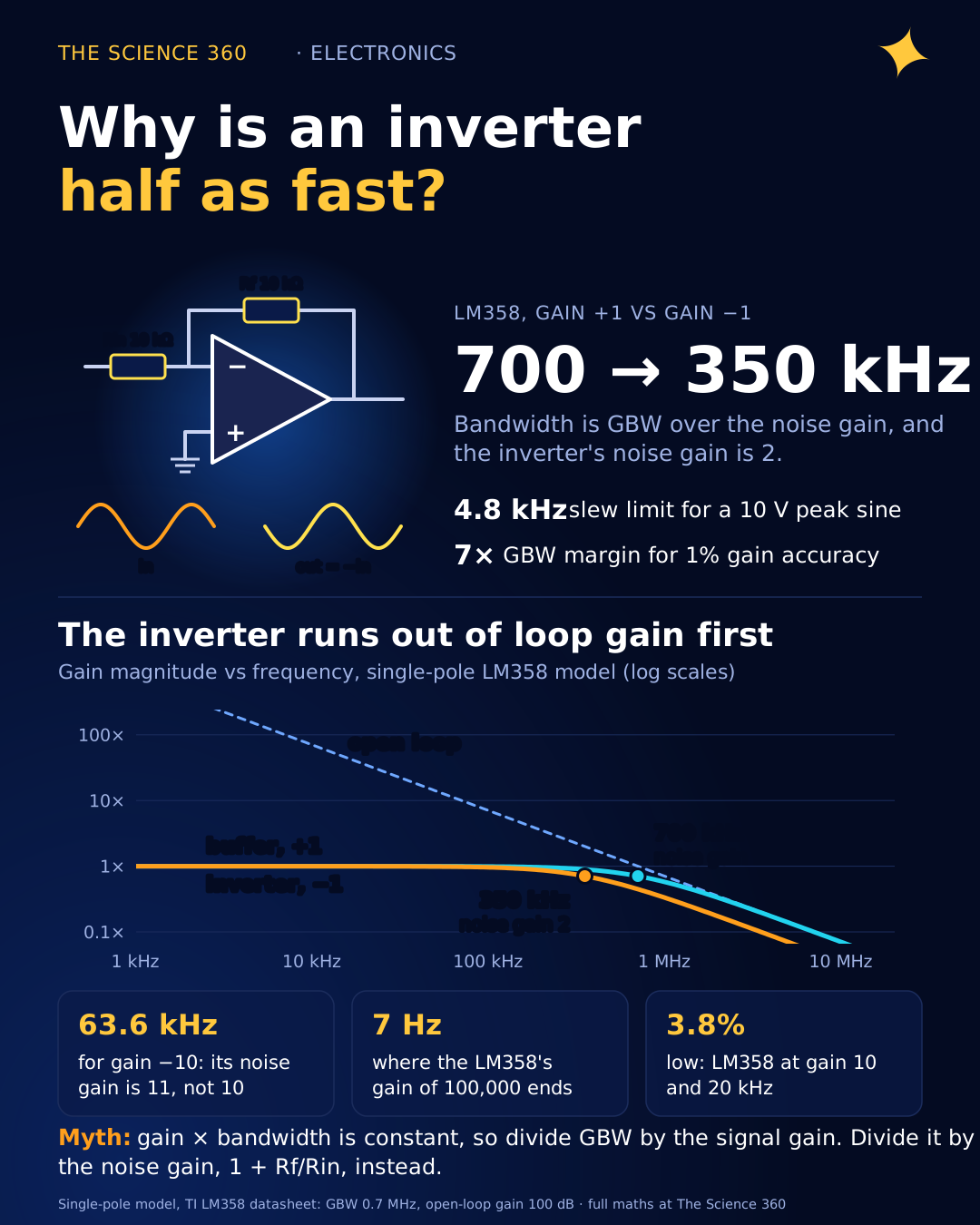
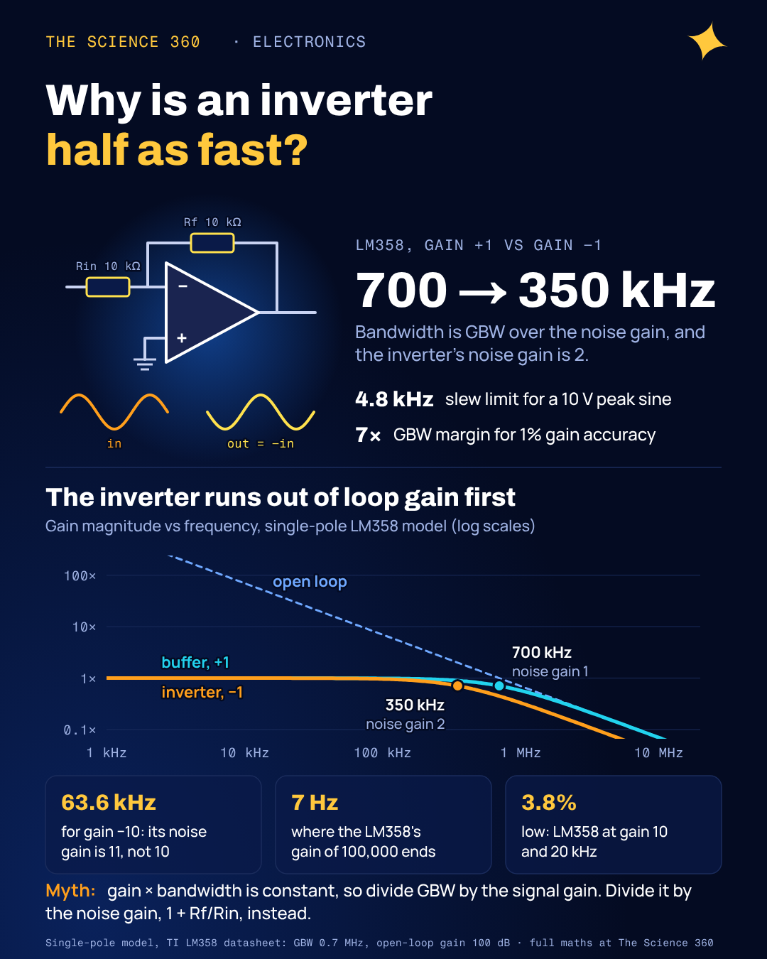
Build an inverting amplifier with two 10 kΩ resistors around an LM358, a gain of −1, and measure its bandwidth. You will get about 350 kHz. Now rewire the same op amp as a plain unity-gain buffer, gain +1, and you get about 700 kHz. Same chip, same gain magnitude, twice the bandwidth. If gain bandwidth product means "gain times bandwidth is constant", one of those measurements has to be wrong.
Neither is. The rule works, but it is easy to multiply by the wrong gain. The top results for this question are mostly distributor glossary entries and short videos that stop at "". This post does the version that survives contact with a real circuit: which gain to use, how much bandwidth you actually need for accurate gain, where the rule bends at low gain, and why slew rate can wreck a signal long before the bandwidth limit.
What is gain bandwidth product?
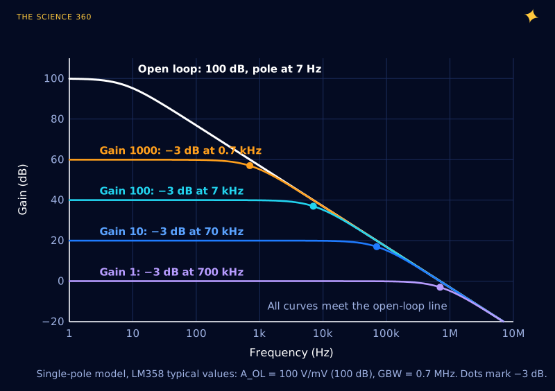
An op amp on its own has enormous gain at DC. TI's LM358 datasheet (revision of October 2024) lists a typical open-loop gain of 100 V/mV, which is 100,000, or 100 dB. That gain does not last. Almost every general-purpose op amp is deliberately built with one dominant pole, a built-in low-pass filter, so that its gain falls at a steady 20 dB per decade over most of its range. A falling line with that slope has a simple property: gain times frequency is the same everywhere on it.
LM358, typical values from the TI datasheet
Open-loop gain A0, gain bandwidth product GBW and dominant pole fp:
Check a point on the slope: at 7 kHz the open-loop gain is
So the "amplifier with a gain of 100,000" is an amplifier with a gain of 100,000 only below about 7 Hz. At 1 kHz it is down to 700. That is why you never use an op amp open loop: you wrap feedback around it and trade the excess gain for accuracy and bandwidth.
A quick correction before going on. You will often see the LM358 quoted at "about 1 MHz". TI's current datasheet lists 0.7 MHz typical for the LM358, LM358A and LM2904, and 1.2 MHz for the newer LM358B, along with slew rates of 0.3 and 0.5 V/µs respectively. The round 1 MHz may come from other manufacturers' versions, which I did not check. Whatever the part, read the actual datasheet for the variant you are buying.
Why is the bandwidth GBW divided by the gain?
With feedback fraction β (the share of the output fed back to the inverting input), the closed-loop gain is . Where the loop gain is large, that is just . Where it falls toward 1, the op amp has run out of spare gain and the response follows the open-loop line down. The handover happens at the frequency where the open-loop gain equals . On a slope where , that frequency is:
Closed-loop bandwidth of a single-pole op amp
is the noise gain: for both the inverting and the non-inverting circuit.
Here is the subtlety. In a non-inverting amplifier, the signal gain is , the same as , so "divide GBW by the gain" works. In an inverting amplifier the signal gain is , but the feedback network is identical, so is still . The bandwidth follows , which is called the noise gain because it is the gain applied to noise (and offset) at the op amp's input. TI's OPA690 datasheet puts it plainly: dividing GBP by the non-inverting signal gain, "also called the noise gain", predicts the closed-loop bandwidth.
Inverting vs non-inverting, LM358 (GBW = 0.7 MHz)
Buffer, gain +1:
Inverter, gain −1 (Rf = Rin):
Non-inverting, gain +10:
Inverting, gain −10 ():
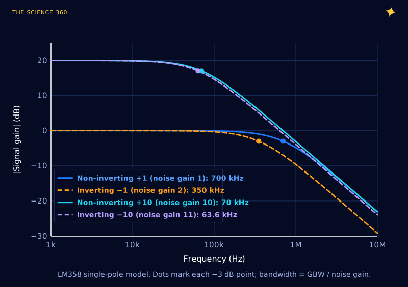
Hugo Coolens made the same point in Electronic Design in 2019 with a 741: open-loop gain 200,000 and open-loop bandwidth 5 Hz, so . The naive rule predicts 1 MHz for a unity-gain inverter; the right answer is 500 kHz. His general form for the inverting circuit is , and he notes the naive version stays within 5% only once the gain is at least about 20.
Noise gain is also why a few circuits surprise people. A summing amplifier with four equal input resistors and the same feedback resistor has a signal gain of −1 from each input, but a noise gain of , so its bandwidth is . A transimpedance amplifier for a photodiode has a signal "gain" in ohms, and its stability is set by a noise gain that rises with frequency because of the diode's capacitance.
How much bandwidth do you actually need?
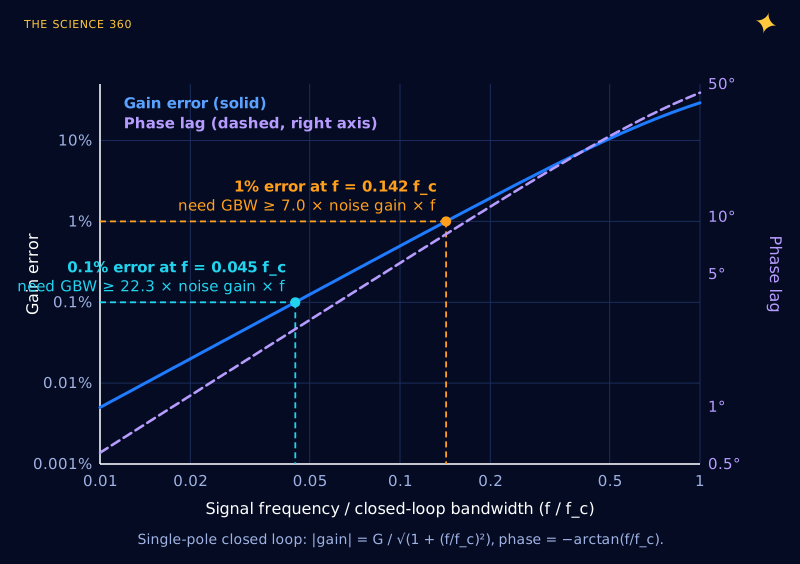
The −3 dB point is where the gain is already 29% low. If you want a gain that is actually accurate, you need to stay well below it. For a single-pole closed loop, the gain falls as and the phase lags by .
Design margin for gain accuracy
1% low:
0.1% low:
Example: gain of +10 at 20 kHz (top of the audio band)
LM358:
TL072 (GBW 5.25 MHz):
A one-line LM358 preamp with a gain of 100 has a bandwidth of , not good enough for audio even before you think about accuracy. A TL072 at the same gain manages 52.5 kHz. Pick the op amp from the GBW you need, not the GBW printed in the headline of the datasheet.
Is gain bandwidth product always constant?
No, and the place it fails is low gain. Real op amps have more than one pole. The second pole, usually somewhere near the unity-gain frequency, adds phase lag that a single-pole model ignores. At high noise gain the loop crosses over far below that second pole and nothing changes. At low noise gain the loop crosses over close to it, the phase margin shrinks, and the closed-loop response develops a bump before it falls. TI's OPA690 datasheet notes that GBP divided by noise gain "only holds true when the phase margin approaches 90°, as in high-gain configurations."
Generic op amp, GBW = 1 MHz, second pole at 1 MHz
Noise gain 10:
Noise gain 2:
Noise gain 1:
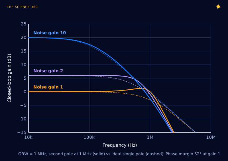
Counter-intuitively, the low-gain circuit has more bandwidth than the rule predicts, but it buys it with peaking, overshoot and less stability margin. With a heavier capacitive load the second pole moves down and the bump grows into oscillation. This is the reason some fast op amps are sold as "decompensated", stable only above a minimum noise gain, and why "unity-gain stable" is a specification at all. Current-feedback op amps break the rule more completely: their bandwidth is set mainly by the feedback resistor rather than by the gain.
Why does my op amp distort a sine wave that is well inside its bandwidth?
Because of slew rate, which is a different limit altogether. GBW describes small signals, where everything inside the op amp behaves linearly. Slew rate (SR) is the fastest the output can change, set by how much current the input stage can push into the internal compensation capacitor. Once the output is asked to move faster, the op amp is no longer a linear amplifier: the output just ramps at SR until it catches up.
Full-power bandwidth from slew rate
A sine changes fastest at its zero crossings:
Largest undistorted frequency:
LM358, SR = 0.3 V/µs, Vp = 10 V:
Same chip at Vp = 1 V: 47.7 kHz.
LM358B (0.5 V/µs) at 10 V: 8.0 kHz. TL072 (20 V/µs) at 10 V: 318 kHz.
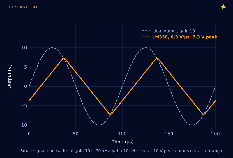
There is a neat way to see where the two limits cross. In the linear regime an output step ΔV settles exponentially with time constant , so its initial rate of change is . That exceeds the slew rate when .
Largest step that stays linear, LM358 at gain +10
Any output step bigger than about 0.7 V is slew-limited, not bandwidth-limited.
That is why "the scope shows a triangle" and "the frequency response looks fine on a small test signal" are both common reports about the same circuit. The fix is either a faster op amp or a smaller swing. When you are filtering a slow sensor signal, as in an RC time-constant problem, neither limit matters much; when you are driving a 10 V audio line, both do.
A checklist for choosing an op amp by bandwidth
Work out the noise gain, (or the effective version for summing and transimpedance circuits). Multiply it by the highest signal frequency and by 7 for 1% accuracy, or 22 for 0.1%: that is your minimum GBW. Compute for your largest swing and compare it with the slew rate, with margin, because both numbers on the datasheet are typical values. If your noise gain is close to 1 or you are driving capacitance, look at the phase margin or the small-signal step response plots rather than GBW alone. And if the op amp is buffering a reference or feeding an ADC, remember that its output impedance rises with frequency as the loop gain falls, which is where a local decoupling capacitor earns its place.
FAQ
What is the gain bandwidth product of an op amp?
For most voltage-feedback op amps the open-loop gain falls at 20 dB per decade over a wide range, so gain times frequency is constant along that slope. That constant is the gain bandwidth product. In a feedback circuit the closed-loop bandwidth is roughly the gain bandwidth product divided by the circuit's noise gain.
Why does an inverting amplifier with gain -1 have half the bandwidth?
Bandwidth depends on the noise gain, , which is the gain the op amp applies to a signal at its non-inverting input. A gain of −1 uses equal resistors, so its noise gain is 2 and its bandwidth is half the gain bandwidth product, while a +1 buffer has noise gain 1 and the full bandwidth.
Is slew rate the same as bandwidth?
No. Gain bandwidth product limits small signals; slew rate is the fastest the output voltage can change, and it limits large signals. A sine of peak voltage needs a slew rate of . An LM358 at 0.3 V per microsecond can only deliver a 10 V peak sine up to about 4.8 kHz, even though its small-signal bandwidth at gain 10 is 70 kHz.
What is the gain bandwidth product of the LM358?
Texas Instruments' current LM358 datasheet lists a typical gain bandwidth product of 0.7 MHz and a slew rate of 0.3 V per microsecond for the LM358 and LM358A. The newer LM358B is listed at 1.2 MHz and 0.5 V per microsecond. Typical values vary between parts, so leave margin.
How much gain bandwidth product do I need?
To keep a single-pole amplifier's gain error below 1 percent at frequency f, you need a gain bandwidth product of at least about 7 times the noise gain times f. For 0.1 percent you need about 22 times. Then check slew rate separately, using for your largest output swing.
Related on The Science 360
Sources
- Texas Instruments, LM358, LM358A, LM358B, LM2904 datasheet, SLOS068AB, revised October 2024 (GBW 0.7 MHz and SR 0.3 V/µs for LM358; 1.2 MHz and 0.5 V/µs for LM358B; AOL 100 V/mV typ): ti.com/lit/ds/symlink/lm358.pdf
- Texas Instruments, TL07x datasheet, SLOS080W, revised July 2025 (GBW 5.25 MHz, 3 MHz for NS/PS packages and M grade; SR 20 V/µs typ): ti.com/lit/ds/symlink/tl072.pdf
- Texas Instruments, OPA690 datasheet (GBP divided by noise gain; holds when phase margin approaches 90°): ti.com/product/OPA690
- H. Coolens, "Gain-Bandwidth Product is Not (Always) Constant", Electronic Design, April 2019: electronicdesign.com
Method note: all frequency responses are computed from single-pole (and, in Figure 4, two-pole) transfer functions using the datasheet typical values. Figure 5 integrates a first-order closed loop with a hard slew-rate clamp. Real parts vary with supply voltage, load and temperature, and typical values are not guaranteed.
Header image: NASA (image iss018e027439), regraded for this article.