How PWM Dims LEDs and Controls Motor Speed
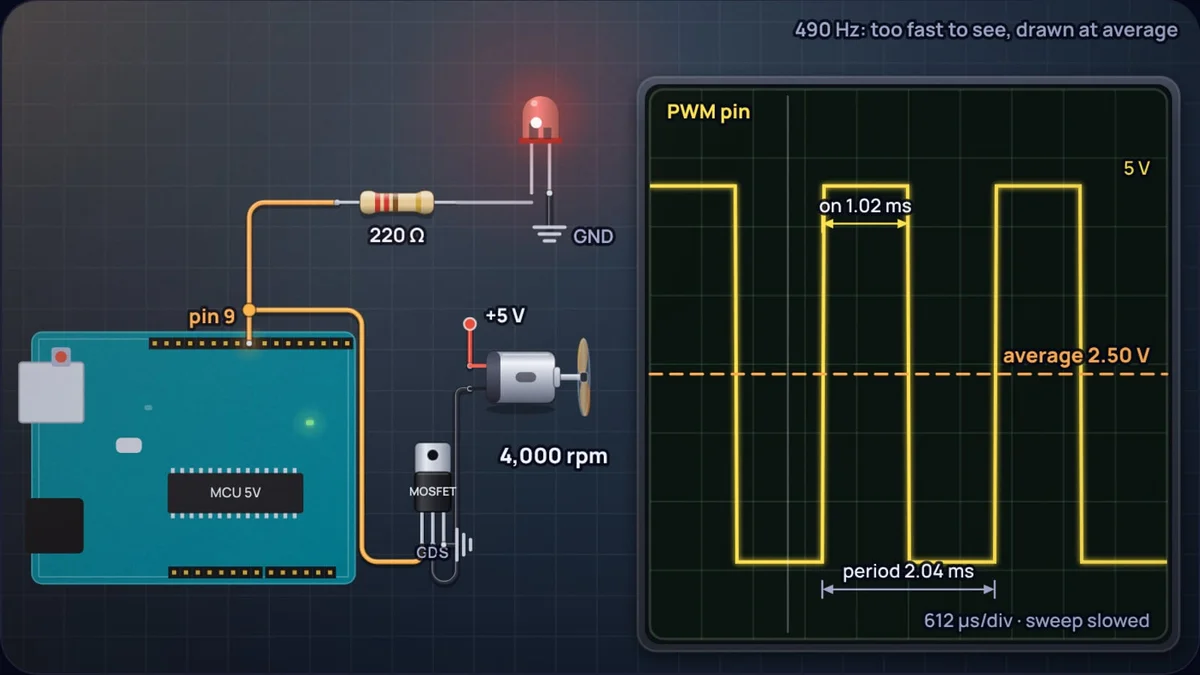
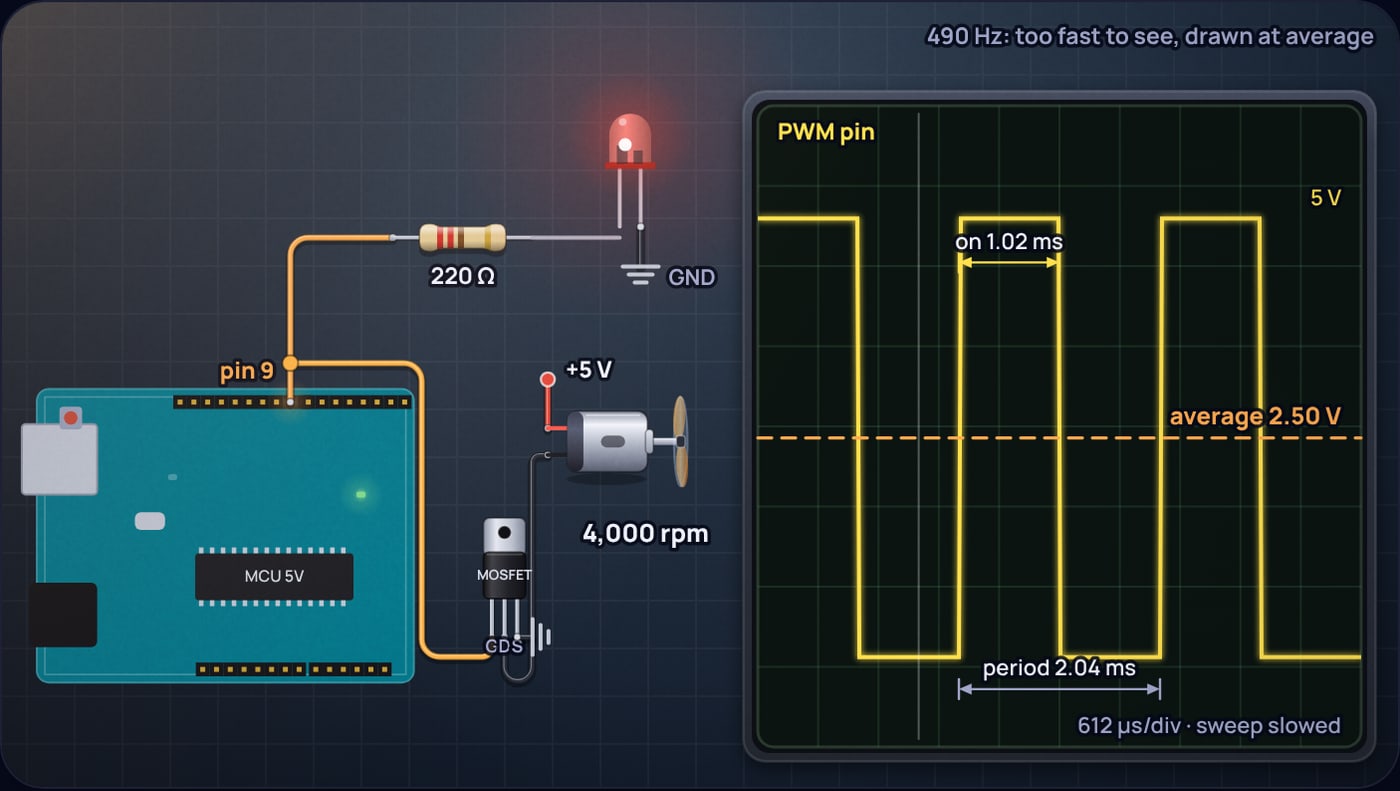
Call analogWrite(9, 128) on an Arduino Uno and pin 9 does not output 2.5 V. It outputs 5 V for 1.02 ms, then 0 V for 1.02 ms, about 490 times a second, and it keeps doing that until you tell it otherwise. An LED on that pin looks dimmer. A motor on that pin, through a transistor, runs slower. Neither is getting less voltage during a pulse. They are getting full voltage for less of the time.
That is pulse width modulation, and it is how almost every microcontroller dims a light or sets a fan speed. This post explains what the LED and the motor are actually responding to, why the brightness you see does not match the number you wrote, and how to pick the frequency. Every figure comes from the PWM duty cycle simulator, which drives an LED, a motor and an RC filter from the same pin and shows the waveform on a scope.
What is a PWM signal, exactly?
A PWM signal has two numbers. The frequency is how many on-off cycles happen per second; its inverse is the period T. The duty cycle D is the fraction of each period the signal spends high. Nothing else changes: the high level is always the full supply of the pin, and the low level is always 0 V.
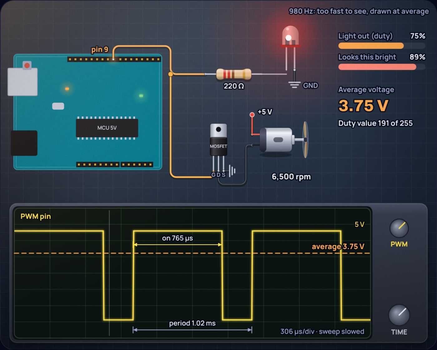
On an Arduino, analogWrite takes a value from 0 to 255, so . The Arduino reference lists 490 Hz on most Uno PWM pins and 980 Hz on pins 5 and 6. Those come straight from the 16 MHz clock: the timer behind pins 5 and 6 runs in fast PWM mode at 16 MHz ÷ 64 ÷ 256 = 976.6 Hz, and the others in phase-correct mode at 16 MHz ÷ 64 ÷ 510 = 490.2 Hz.
The average over one period is simple, because the signal is either V or 0:
| Duty | analogWrite | Average at 5 V | Average at 3.3 V | Looks this bright |
|---|---|---|---|---|
| 5% | 13 | 0.25 V | 0.17 V | 27% |
| 10% | 26 | 0.50 V | 0.33 V | 38% |
| 25% | 64 | 1.25 V | 0.83 V | 57% |
| 50% | 128 | 2.50 V | 1.65 V | 76% |
| 75% | 191 | 3.75 V | 2.48 V | 89% |
| 100% | 255 | 5.00 V | 3.30 V | 100% |
The last column is the surprise, and it gets its own section below.
How does PWM dim an LED?
An LED cannot be "half on" in the PWM sense. During each pulse it gets the full pin voltage through its resistor, and between pulses it gets nothing. With a red LED (about 2.0 V) and a 220 Ω resistor on a 5 V pin:
Light output from an LED is close to proportional to current, so over a period the LED emits about half the light it would at 100%. The current during each pulse is still 13.6 mA, which is why the resistor stays in the circuit.
This is the main advantage of PWM dimming over turning down the current: the LED always runs at the current it was designed for, so its colour does not shift and the resistor value from the LED resistor guide still applies. The reason the series resistor matters at all is covered in why LEDs need a resistor.
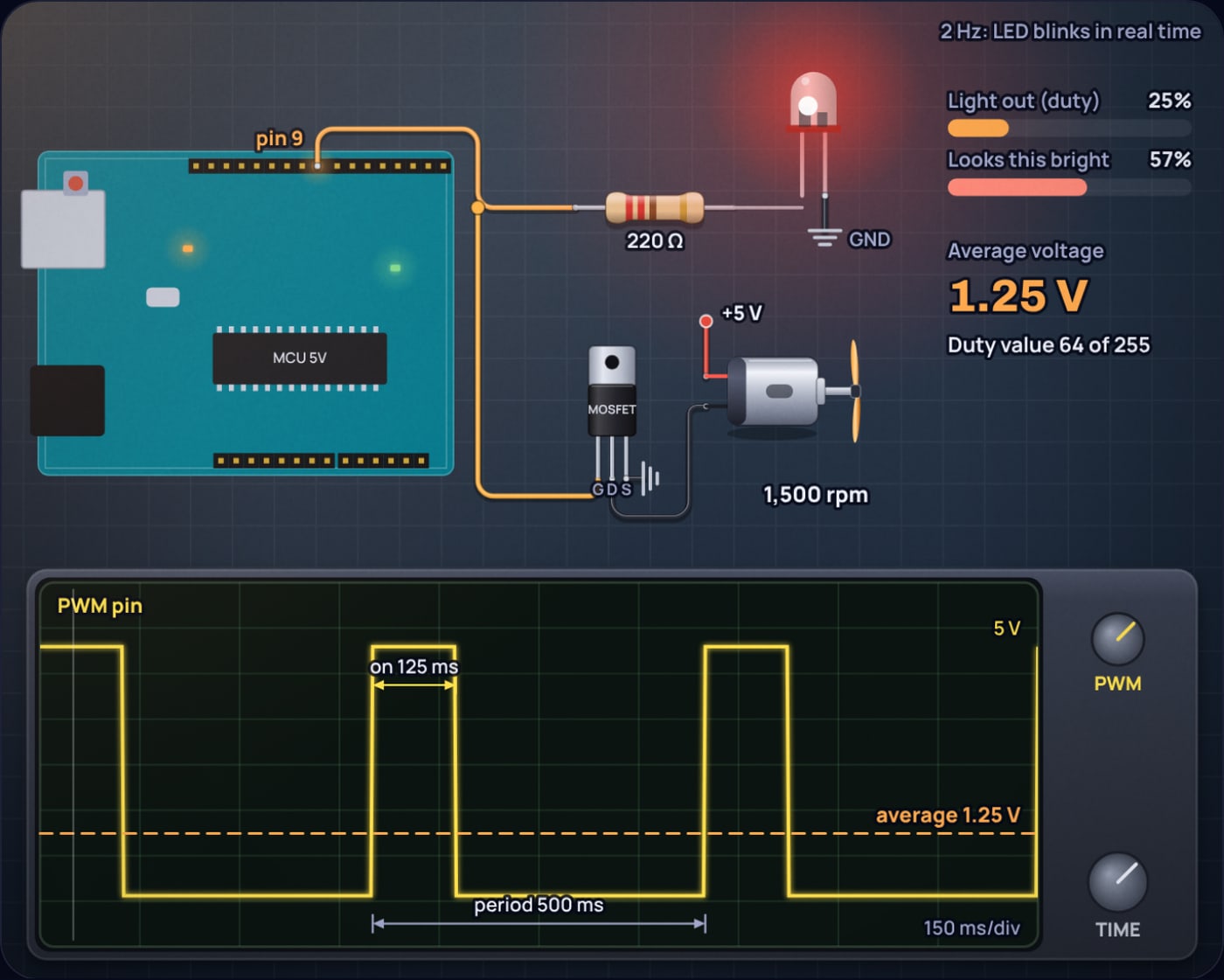
What makes it look steady is your eye. A study in Scientific Reports by Davis, Hsieh and Lee found that sensitivity to uniform flicker drops to zero near 65 Hz, so 490 flashes a second look like a continuous glow, at least while the LED and your eyes hold still. Figure 2 shows what happens if you slow the PWM down to 2 Hz: the duty cycle and the average are the same as ever, but now you see every flash.
Why does 50% duty look much brighter than half?
Because the eye compresses brightness. The standard model is CIE lightness, L*, which for most of its range is a cube root of the light reaching the eye relative to a reference:
Take the LED's light output as a fraction of full, Y/Yn = D.
Half the light looks 76% as bright. To look half as bright, the LED needs only about 18% duty.
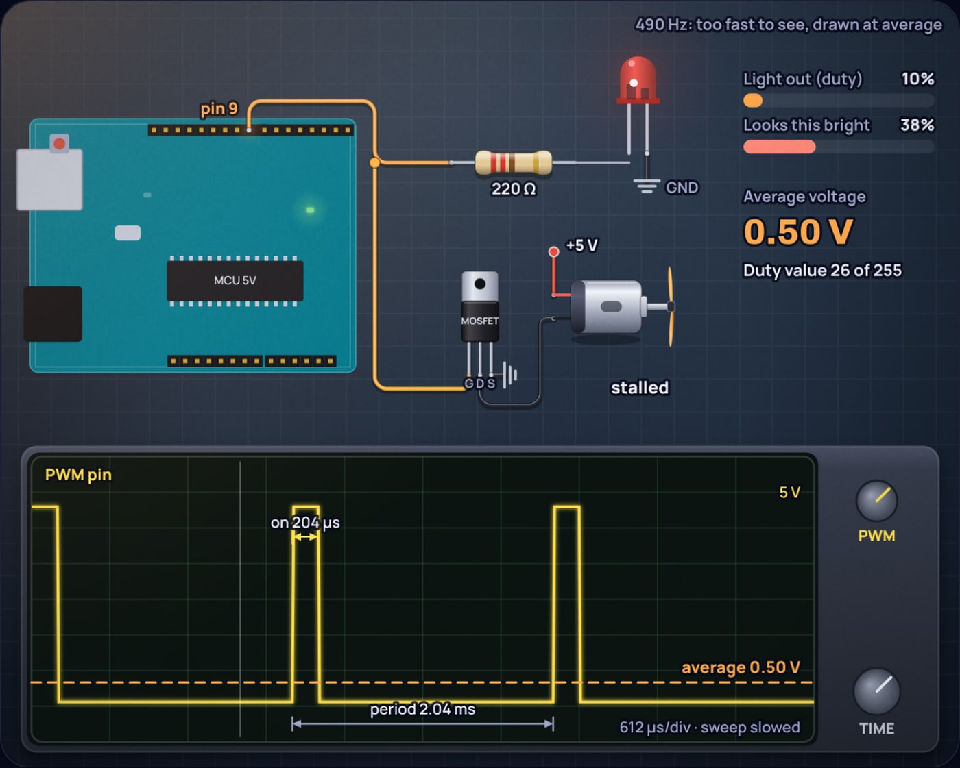
That is the common misconception about PWM dimming: people expect duty to equal brightness, write a fade loop that steps analogWrite from 0 to 255, and find that the LED gets bright almost immediately and then barely changes for the second half of the fade. The fix is a gamma table: map the brightness you want to the duty you need with something close to or the exact inverse of L*. Figure 3 shows the low end, where 10% duty still looks more than a third bright.
How does PWM control motor speed?
A microcontroller pin cannot power a motor directly; it can supply a few tens of milliamps and a small motor wants hundreds. So the pin drives the gate of a logic-level MOSFET, and the MOSFET switches the motor's own supply on and off. A diode across the motor catches the voltage spike each time the current is cut, the same job described in the flyback diode post.
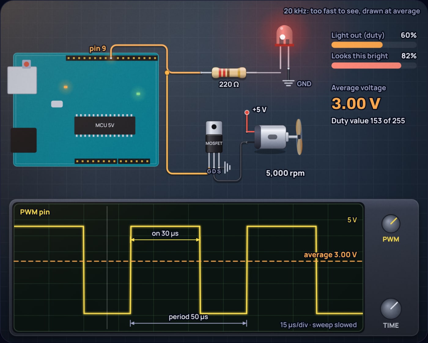
The motor responds to the average for two reasons. Its winding inductance smooths the current within each pulse, and its rotor has inertia, so it cannot speed up and slow down 490 times a second. Our simulator models the rotor with a mechanical time constant of 50 ms (illustrative, for a small hobby motor), and the speed ripple follows from the same first-order maths as an RC filter:
Supply 5 V, duty 60%, the illustrative motor at about 2,000 rpm per volt above a 0.5 V starting threshold.
At 490 Hz the rotor's speed wobbles by only about 1% per cycle. At 10 Hz and 50% duty it would surge by about ±38%, which you can hear and feel.
Real motors do not start at zero duty either. Friction holds them until the average voltage is high enough, so a fan that runs happily at 30% may refuse to start from rest at 15%. Motor code often kicks the motor at full duty for a moment and then drops to the target.
To reverse the motor as well as change its speed you need four switches instead of one, which is the H-bridge.
What PWM frequency should you use?
Frequency does not change the average, but it changes almost everything else.
- Below about 65 Hz an LED visibly flickers even when you hold still.
- 65 Hz to about 500 Hz looks steady when still, but a moving LED or a quick glance across it leaves a dotted trail. Davis and colleagues found that for the median viewer these artifacts disappear only above about 500 Hz.
- IEEE 1789, summarised by the US Department of Energy, sets a low-risk limit on percent flicker of 0.08 × f between 90 Hz and 1250 Hz. Full on/off PWM is 100% flicker, so it only counts as low risk above 1250 Hz. Arduino's default 490 Hz is fine for an indicator, not for room lighting.
- Motors want a few hundred hertz at least so the rotor does not surge, and many drivers use 20 kHz or more to push the coil whine above hearing. The cost is more switching loss: at 20 kHz the transistor makes about 40 times as many transitions per second as at 490 Hz.
How do you turn PWM into a real DC voltage?
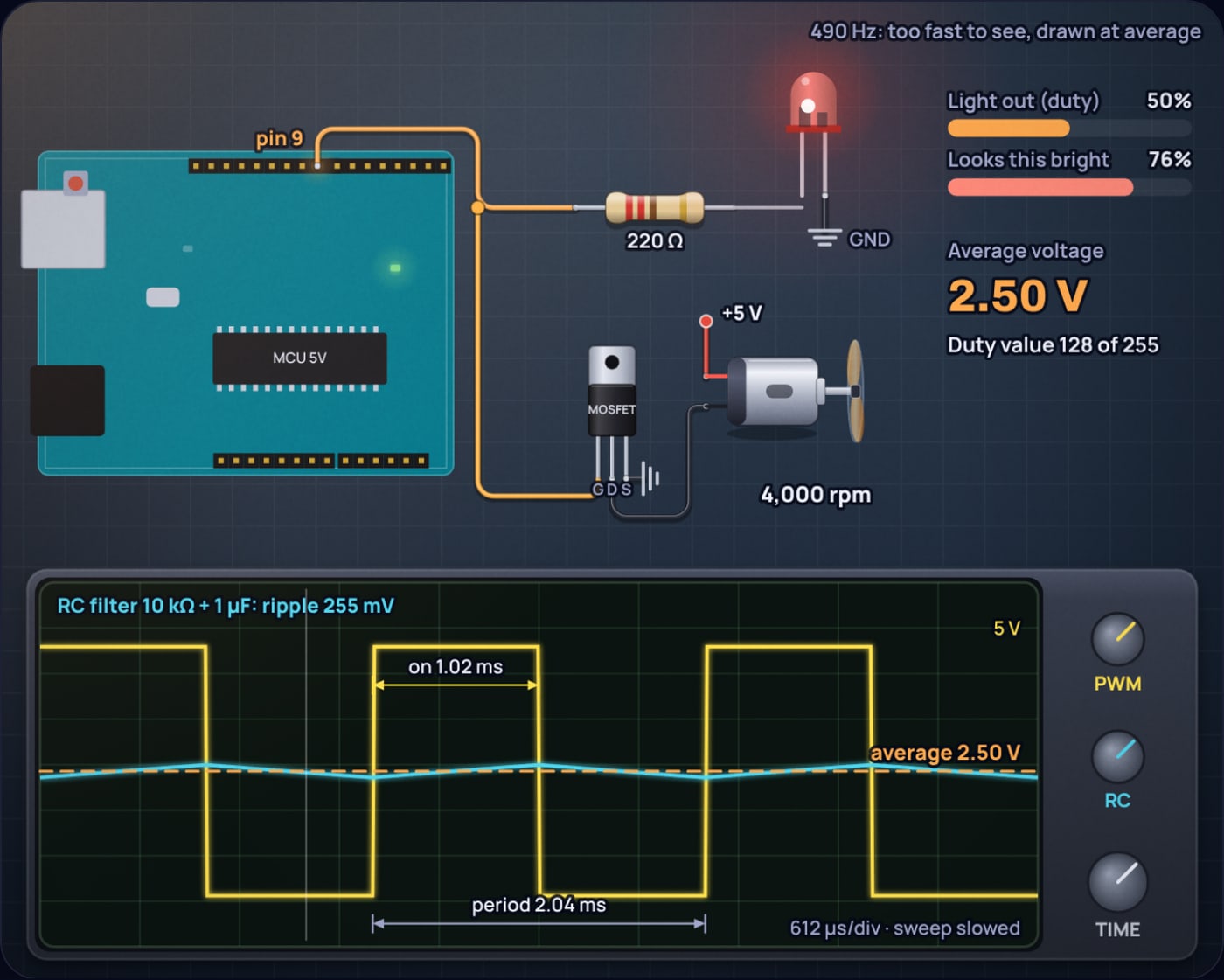
Add a low-pass filter. A resistor in series with the pin and a capacitor to ground form an RC filter that, like the motor, cannot follow the pulses. It charges a little during each high time and discharges a little during each low time, and settles around the average with a small ripple. When RC is much longer than the period, the peak-to-peak ripple is approximately
With 10 kΩ and 1 µF at 490 Hz and 50% duty that gives , which is exactly what the simulator's exact calculation shows in Figure 6. Ten times the capacitance gives a tenth of the ripple, 25.5 mV, but the output then takes about 4.6 RC = 0.46 s to settle after the duty changes. The cutoff frequency of this filter, and why its slope is gentler than the textbooks suggest, are covered in the RC low-pass filter post.
Try it yourself
Open the simulator at 10% duty and drag the duty slider slowly upward while watching the two bars: light output climbs in a straight line, perceived brightness races ahead. Then drag the frequency down below 20 Hz and watch the LED start blinking and the motor start surging, with the average voltage unchanged the whole time.
Sources
- Arduino reference, analogWrite() (read via the arduinogetstarted.com mirror): 0 to 255 range, 490 Hz and 980 Hz on the Uno, the pins 5 and 6 note.
- Davis, Hsieh and Lee, "Humans perceive flicker artifacts at 500 Hz", Scientific Reports 5, 7861 (2015).
- US Department of Energy, SSL postings on IEEE Std 1789-2015 flicker recommendations (June 2015).
- CIELAB colour space: definition of CIE 1976 lightness L*.
Frequently asked questions
How does PWM dim an LED?
The pin switches the LED fully on and fully off hundreds of times a second. The LED’s light output follows the share of time it is on, the duty cycle, and the eye averages the flashes because they are faster than it can follow. At 25 percent duty the LED emits a quarter of its full light.
How does PWM control motor speed?
A transistor switches the full supply onto the motor in short pulses. The rotor is too heavy to speed up and slow down within each pulse, so it settles at the speed set by the average voltage, which is the supply times the duty cycle. At 60 percent on 5 V the motor sees an average of 3 V.
Why does an LED at 50 percent PWM look brighter than half?
Human brightness perception is roughly a cube root of light output. By the CIE lightness formula, 50 percent of the light looks about 76 percent as bright and 10 percent looks about 38 percent. To look half as bright an LED needs only about 18 percent duty, which is why dimming code uses a gamma table.
What PWM frequency should I use for LEDs and motors?
For LEDs, anything above about 65 Hz looks steady when still, but moving LEDs can show a dotted trail up to around 500 Hz, and IEEE 1789 treats full on/off PWM as low risk above 1250 Hz. For motors, a few hundred hertz works, and 20 kHz or more moves the whine above hearing.
Do I still need a resistor for an LED driven by PWM?
Yes. During each on pulse the LED sees the full pin voltage, so the resistor is what limits the current in the pulse. PWM only changes how long each pulse lasts, not how much current flows during it.
 555 Timer Frequency Formula: Where 1.44 Comes From
 ADC Resolution vs Accuracy: ENOB, INL and the Reference
