What is PWM duty cycle?
Duty cycle is the share of each period that a PWM signal spends high. A 5 V pin at 50% duty is high half the time and low half the time, so its average is 2.5 V; at 25% the average is 1.25 V. The pin never actually sits at those voltages: it switches between 0 and 5 V fast enough that an LED, a motor or a filter only responds to the average. On an Arduino Uno, analogWrite(pin, 128) gives 50% duty at about 490 Hz.
The simulation draws the waveform on a scope with its average as a dashed line, and shows what the pulses do to an LED, a small motor and an RC smoothing filter. It also shows the part most PWM explainers skip: your eye does not see light linearly. At 50% duty the LED puts out half the light but looks about 76% as bright, by the CIE lightness scale. That is why LED dimming code uses a gamma table. For the companion explainer, read how PWM dims LEDs and controls motor speed.
Key results from the simulation
- Average = high voltage × duty: 2.50 V at 50% on a 5 V pin, 0.50 V at 10%, 0.99 V at 30% on a 3.3 V pin.
- analogWrite value = duty × 255: 50% is 128, 10% is 26, 100% is 255. The Arduino reference lists about 490 Hz on most Uno pins and 980 Hz on pins 5 and 6; the timer arithmetic gives 490.2 Hz and 976.6 Hz.
- Brightness is not linear: 10% duty looks 38% as bright and 50% looks 76%. To look half as bright you need only about 18% duty.
- Frequency decides flicker, not brightness: below about 65 Hz a steady LED visibly flickers; above that it looks steady until you move it, when a dotted trail can be visible up to about 500 Hz and beyond. IEEE 1789 treats full on/off PWM as low risk only above 1250 Hz.
- An RC filter turns PWM into DC: 10 kΩ and 1 µF at 490 Hz leave 255 mV of ripple on 2.5 V; 10 µF cuts that to 25.5 mV but takes 0.46 s to settle.
Seven PWM settings to try
Each card loads a setting into the simulator. The LED uses a 220 Ω resistor and a red LED, the motor is an illustrative small hobby motor switched by a logic-level MOSFET, and the filter is a 10 kΩ resistor with the capacitor you choose.
analogWrite(9, 128): half duty on an Uno
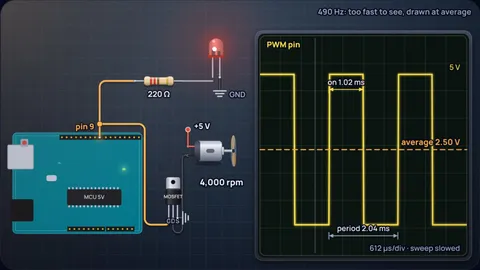
5 V · 490 Hz · 50%The pin is high for 1.02 ms and low for 1.02 ms, about 490 times a second. The average is 2.50 V. During each high pulse the LED gets the full current, (5 − 2.0) ÷ 220 = 13.6 mA, and averaged over the period it gets 6.82 mA.
The LED looks about 76% as bright as fully on, not 50%, because human brightness perception is closer to a cube root of light output than a straight line. The motor runs at about 4,000 rpm in this model, and its rotor is far too heavy to follow 490 Hz, so the speed ripple is only about 1%.
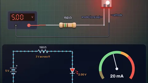
Related reading: Which resistor for the LED
10% duty still looks a third bright
5 V · 490 Hz · 10%At 10% duty (analogWrite 26) the LED gets light for only 0.2 ms of every 2 ms. The average voltage is 0.50 V, but the LED looks about 38% as bright as full on. This is where linear dimming code feels wrong: most of the visible range is squeezed into the bottom fifth of the slider.
A gamma table fixes it by mapping the brightness you want to the duty you need. To look half as bright, the duty has to be about 18%. Notice the motor in the same setting: 0.50 V average is no more than its 0.5 V starting threshold, so it does not turn at all. Real motors stall at low duty too, which is why motor code usually starts at 20 to 30 percent.
At 2 Hz, PWM is just blinking
5 V · 2 Hz · 25%Turn the frequency down to 2 Hz and the trick falls apart. The LED is on for 125 ms and off for 375 ms, and you see every flash. Nothing about the duty cycle changed; the average is still 1.25 V. The difference is only whether the load and your eye can follow the switching.
The motor shows the same thing mechanically. With a rotor time constant around 50 ms, it speeds up in every pulse and coasts down in every gap. At 10 Hz and 50% the model speed swings by about ±23% around the mean. Use a few hundred hertz or more for motors.
Pins 5 and 6 run twice as fast
5 V · 980 Hz · 75%On an Uno, pins 5 and 6 share Timer0 with millis() and delay(), which runs in fast PWM mode, so they switch at 16 MHz ÷ 64 ÷ 256 = 976.6 Hz. The other PWM pins use phase-correct mode at 16 MHz ÷ 64 ÷ 510 = 490.2 Hz. At 75% duty either one averages 3.75 V.
The Arduino reference also notes that pins 5 and 6 give slightly higher duty than asked for at low settings, a side effect of that shared timer. Faster is better for flicker and for RC filters, so if you have a choice for an LED, pins 5 and 6 are the better ones.
Why motor drivers use 20 kHz
5 V · 20 kHz · 60%A motor winding is a coil of wire on a magnetic core, and at a few hundred hertz the pulses make it hum or whine like a tiny speaker. Moving the PWM frequency to 20 kHz or above puts that sound beyond most people's hearing. The average is still 3.00 V and the model speed 5,000 rpm.
The cost is switching loss: every edge spends a little energy in the transistor, so 20 kHz heats a MOSFET about 40 times more per second than 490 Hz does for the same edges. For small motors with a logic-level MOSFET this is still tiny. The H-bridge motor driver post covers reversing direction.
Related reading: H-bridge motor drivers
An RC filter turns PWM into a real voltage
5 V · 490 Hz · 50% · 10 kΩ + 1 microfaradPut a 10 kΩ resistor in series with the pin and a 1 µF capacitor to ground, and the capacitor can no longer follow the pulses. It settles near the average, 2.50 V, with 255 mV of ripple. That is a crude digital-to-analog converter for setting a reference or a bias.
The trade is speed. A bigger capacitor gives less ripple (2.4 V with 100 nF, 255 mV with 1 µF, 25.5 mV with 10 µF) but takes longer to follow a change in duty: about 4.6 RC to settle within 1%, 46 ms for 1 µF. The RC low-pass filter post works the cutoff frequency for this exact case.
Related reading: RC low-pass cutoff
The same duty on a 3.3 V board
3.3 V · 1 kHz · 30%On a 3.3 V board the high level is 3.3 V, so 30% duty averages 0.99 V instead of 1.50 V. The duty value is identical (77 out of 255 at 8-bit resolution), so the same code produces a lower average voltage and a dimmer LED.
The LED current during each pulse also drops: (3.3 − 2.0) ÷ 220 = 5.91 mA instead of 13.6 mA. Boards with LEDC or PWM peripherals usually let you pick both frequency and resolution, so 1 kHz at 8 bits or 20 kHz at 10 bits are both easy.
PWM duty, average voltage and perceived brightness
| Duty | analogWrite | Average at 5 V | Average at 3.3 V | Looks this bright | Motor (model) |
|---|---|---|---|---|---|
| 5% | 13 | 0.25 V | 0.17 V | 27% | 0 rpm |
| 10% | 26 | 0.50 V | 0.33 V | 38% | 0 rpm |
| 25% | 64 | 1.25 V | 0.82 V | 57% | 1,500 rpm |
| 50% | 128 | 2.50 V | 1.65 V | 76% | 4,000 rpm |
| 75% | 191 | 3.75 V | 2.47 V | 89% | 6,500 rpm |
| 90% | 230 | 4.50 V | 2.97 V | 96% | 8,000 rpm |
| 100% | 255 | 5.00 V | 3.30 V | 100% | 9,000 rpm |
Perceived brightness is the CIE 1976 lightness L* of the light output relative to full on. Motor speeds are for an illustrative small hobby motor (about 2,000 rpm per volt with no load, needing about 0.5 V to start) and will differ for your motor.
How the simulation works
The PWM signal is an ideal square wave: the pin is at the high level (5 V or 3.3 V) for duty × period and at 0 V for the rest. Its average over a period is high level × duty, drawn as the dashed orange line on the scope. The analogWrite value is duty × 255, rounded, which is how the Arduino reference defines it.
The LED uses a 220 Ω resistor and a 2.0 V red LED, so it gets (high level − 2.0 V) ÷ 220 Ω during each pulse and that times the duty on average. Light output is proportional to the average current, and the bars compare it with CIE 1976 lightness, L* = 116 (Y)^(1/3) − 16, the standard model of how bright a light looks relative to a reference.
The RC filter and the motor use the same first-order maths. In steady state the filtered voltage climbs toward the high level during each pulse and decays toward 0 V in each gap, between V_max = V (1 − e^(−DT/τ)) ÷ (1 − e^(−T/τ)) and V_min = V_max e^(−(1 − D)T/τ). For the filter τ = 10 kΩ × C. For the motor τ is an illustrative 50 ms mechanical time constant, which is why slow PWM makes it surge.
Up to 15 Hz the LED and the scope cursor run in real time. Above that the LED is drawn at its average brightness, which is what a steady eye sees, and the scope sweep is slowed to 1.5 seconds per screen. The propeller's drawn spin is also slowed, since a few thousand rpm would alias on a 60 Hz screen.
What the model leaves out
- Rise and fall times: real pins take tens of nanoseconds to switch, and long wires ring. Irrelevant at 490 Hz, visible on a scope at hundreds of kilohertz.
- Motor electrical details: the winding inductance smooths the current within each pulse, and a flyback diode is needed across the motor to protect the transistor. The motor here is a simplified speed model, not a specific part.
- LED temperature and efficiency: LED light output is only roughly proportional to current. At very low duty and current the LED is slightly more efficient per milliamp.
- Eye adaptation: CIE lightness assumes a fixed viewing condition. In a dark room a dim LED looks brighter than the bars suggest.
- Arduino timer quirks: pins 5 and 6 can give slightly more than the requested duty at low values, and analogWrite(pin, 0) and 255 force the pin fully low and high. The simulator treats every value as ideal.
Common misconceptions
“PWM lowers the voltage.” No. The pin only ever outputs 0 V or the full high level. The load sees the average only because it is too slow to follow the switching. That is why an LED on PWM still needs its current-limiting resistor.
“50% duty means half as bright.” Half the light, yes; half the perceived brightness, no. Our eyes compress brightness, so 50% duty looks about three quarters bright, and smooth fades need a gamma-corrected duty table.
Frequently asked questions
What is a PWM duty cycle?
The fraction of each period that the PWM signal is high, given as a percentage. 25% duty means the pin is high for a quarter of every cycle and low for the rest. The average voltage is the high level times the duty, so 25% on a 5 V pin averages 1.25 V.
How do I calculate the average voltage of a PWM signal?
Multiply the high voltage by the duty cycle. A 5 V pin at 50% averages 2.50 V, at 10% it averages 0.50 V, and a 3.3 V pin at 30% averages 0.99 V. This assumes the low level is 0 V.
What PWM frequency does Arduino analogWrite use?
On an Uno, about 490 Hz on pins 3, 9, 10 and 11 and about 980 Hz on pins 5 and 6, according to the Arduino reference. The exact values from the 16 MHz clock are 490.2 Hz and 976.6 Hz. Other boards differ; the reference lists them per board.
What analogWrite value gives 50% duty?
Duty is value ÷ 255, so 50% is about 127.5. analogWrite(pin, 128) gives 50.2% and 127 gives 49.8%. The simulator rounds to 128.
What PWM frequency avoids LED flicker?
Steady flicker disappears for most people above about 65 Hz, but a moving LED can show a dotted trail up to about 500 Hz or more. IEEE 1789 counts full on/off PWM as low risk only above 1250 Hz. Arduino's 490 Hz is outside that band; a few kilohertz is a safe choice for lighting.
Why does an LED at 50% PWM look brighter than half?
Because perceived brightness is roughly the cube root of light output. By the CIE lightness formula, 50% light looks about 76% as bright and 10% looks about 38%. To look half as bright, use about 18% duty.
Keep learning
How PWM Dims LEDs and Controls Motor Speed
PWM switches a pin fully on and off. Why an LED looks dimmer, why a motor slows, why 50% duty looks 76% bright, and what frequency to use, with numbers.

RC Low Pass Filter Cutoff Frequency: What −3 dB Means
fc = 1/(2πRC) is where the output is 0.707 of the input, half power and −45°. Why the slope there is only 10 dB/decade, and how loading moves it.

How Does an H-Bridge Work? Decay, Dead Time, Losses
Four switches reverse a motor, but the details decide whether it works: shoot-through and dead time, brake vs coast, why an L298 loses 2.5 V and PWM ripple.
What Resistor for an LED on Arduino 5V and 3.3V?
Resistor values for every LED colour on Arduino 5V and ESP32 3.3V pins, with the pin limits, worked examples and why a white LED on 3.3V is a trap.