What Does 104 Mean on a Capacitor? Codes Explained
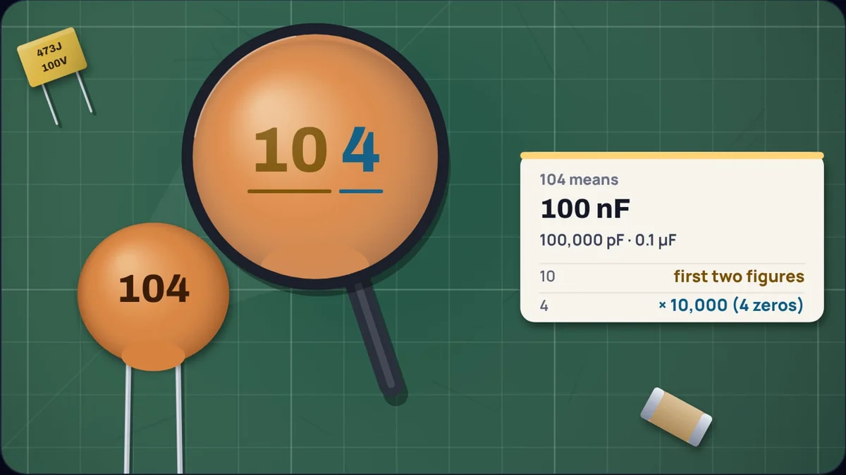
Tip a bag of ceramic capacitors from a starter kit onto the bench and most of the little orange discs will say 104. Nowhere on them does it say 104 of anything, and it is not 104 picofarads either. It is 100,000 picofarads, the 100 nF capacitor that sits next to the power pins of almost every chip on almost every board.
The code is short because the parts are small: two figures and a count of zeros, sometimes with a letter for tolerance and a prefix for voltage. Once you know the pattern you can read any of them, and you can check your reading in our capacitor code calculator, which magnifies the marking and colours each part of the code by what it means.
How do you read a three-digit capacitor code?
Take the first two digits as a number, then write as many zeros after it as the third digit says. The answer is always in picofarads. Vishay's ordering guide for multilayer ceramic capacitors puts it in one sentence: the first two digits are significant, the third is a multiplier. As a formula, with and the first two digits and the third:
For 104 that is 10 times ten to the fourth:
Example 1: 104
Every step between picofarads, nanofarads and microfarads is a factor of a thousand. So to turn the result into nanofarads, divide by 1,000, and to reach microfarads, divide by 1,000 again. That is why the same part appears as 100 nF on a modern schematic, 0.1 µF on an older one and 100,000 pF in a datasheet table.
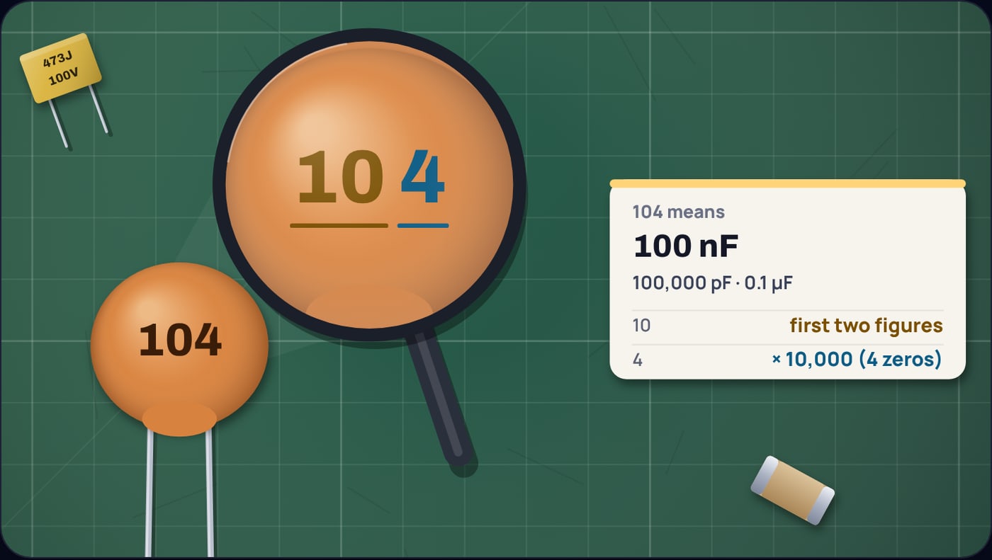
The pattern runs through the whole family. 101 is 100 pF, 102 is 1 nF, 103 is 10 nF, 104 is 100 nF and 105 is 1 µF. Swap the first two digits and you get the rest of the range: 220 pF is 221, 4.7 nF is 472 and 470 nF is 474.
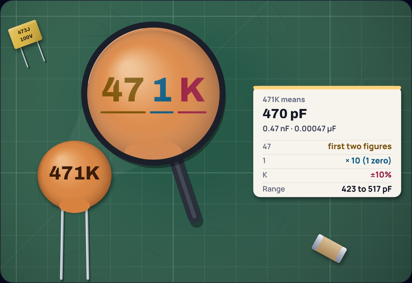
Why is 471 not 471 pF?
Because the last digit is never a figure of the value. It is only a multiplier. 471 is 47 followed by one zero, 470 pF, and it is a common slip to read it as 471 pF. The same rule makes the smallest codes look odd: 470 is 47 pF (no zeros added) and 100 is 10 pF, not 100 pF.
Third digits of 7, 8 and 9 do not appear in capacitor value codes, and the calculator rejects them. If you see one, you are probably looking at a date code, a part number or a resistor.
What do the letters after the number mean?
A single letter straight after the three digits is the tolerance: how far the real capacitance may sit from the printed value. These are the letters in Vishay's MLCC ordering guide:
- F, G, H: ±1%, ±2% and ±3%, for precision parts.
- J, K, M: ±5%, ±10% and ±20%, the three tolerances KEMET offers on its X7R chips and the ones you will meet most often.
- Z: 20% below to 80% above the printed value. KEMET offers its Y5V parts only as Z or ±20%.
- B, C, D and V: ±0.1 pF, ±0.25 pF, ±0.5 pF and ±0.05 pF, used on values below 10 pF, where a percentage would be a tiny fraction of a picofarad.
To turn a tolerance into a range, multiply the value by one minus and one plus the percentage:
Example 2: the range of 104K
Do not mistake the tolerance letter for a unit. 104K is not 104 kilo anything, and 105M is 1 µF ±20%, not a megafarad.
What does 2A104J mean on a film capacitor?
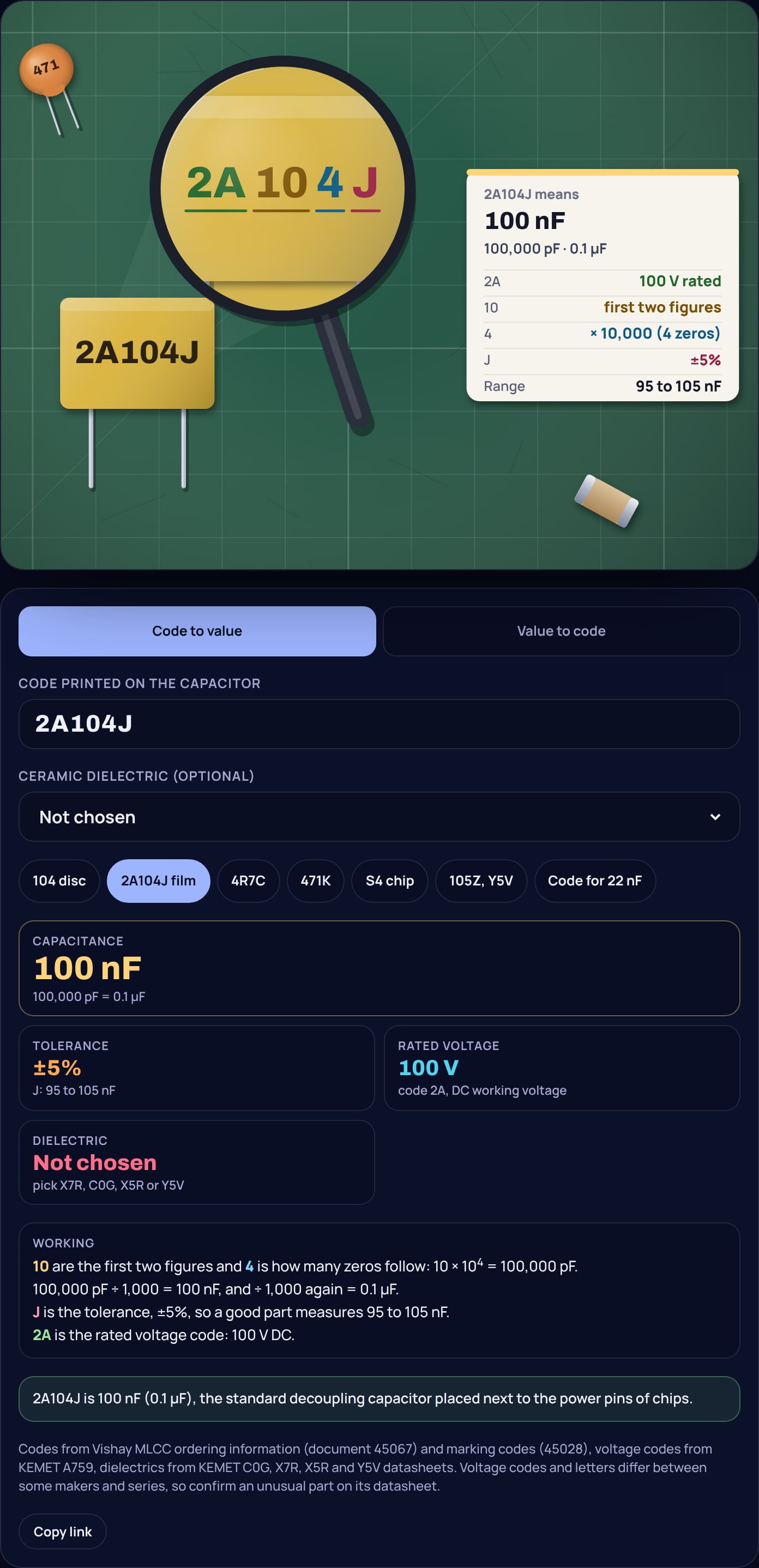
Boxed film capacitors usually have room for the full specification, and many print it as one string: a voltage code, the value code and the tolerance letter. The two characters at the front are the rated voltage. KEMET's datasheet for its A759 series lists the codes it uses: 0J is 6.3 V, 1A is 10 V, 1C is 16 V, 1E is 25 V, 1V is 35 V, 1H is 50 V, 1J is 63 V, 2A is 100 V, 2C is 160 V and 2E is 250 V. So 2A104J is a 100 V, 100 nF, ±5% capacitor.
Example 3: 2A104J
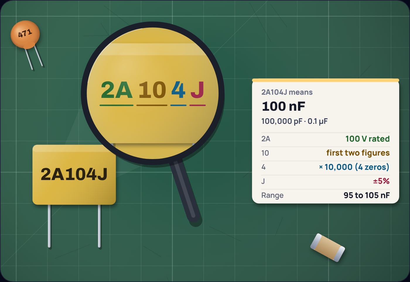
Other parts write the voltage in full instead, such as 104K 100V, and the calculator reads that too. Be careful with voltage codes on parts you cannot identify. They are not universal: KEMET's PEG227 axial electrolytic series, for example, uses single letters such as H for 25 V and M for 63 V. When a code does not match the common table, the datasheet for that exact series is the only reliable key.
How are values below 10 pF written?
A two-figure code cannot go below 10 pF, so small values use the letter R as the decimal point. 4R7 is 4.7 pF and 0R5 is 0.5 pF. Vishay's guide gives 0R3 for 0.3 pF as its own example. These parts usually carry a tolerance in picofarads, so 4R7C is 4.7 pF ±0.25 pF:
Example 4: 4R7C
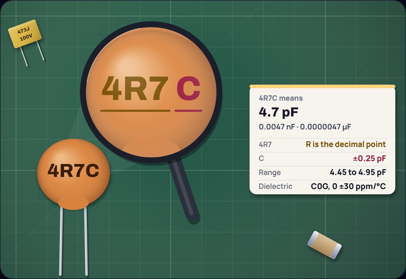
Capacitors this small set frequencies: the load capacitors on a crystal, a tuned circuit in a radio, a compensation capacitor in an amplifier. If you are choosing one for a crystal, our guide to crystal load capacitor values shows how the board's stray capacitance is part of the sum.
What about tiny chip capacitors?
Most surface-mount ceramic chips have no marking at all, because there is no room and the value lives on the reel label. Some do carry a two-character laser mark from a scheme that Vishay documents in its MLCC marking guide. The letter stands for the significant figures, taken from the E24 series (A for 1.0, J for 2.2, S for 4.7, Z for 9.1), with a few lower-case letters for values such as 2.5 and 3.5. The digit is the power of ten, and 9 means divide by ten.
Example 5: S4 on a chip
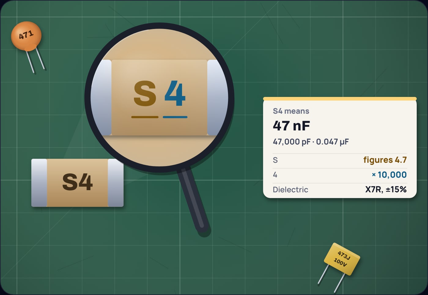
Letter codes are case sensitive. A capital A is 1.0, but a lower-case a is 2.5, so type them exactly as printed.
What do X7R, C0G and Y5V mean?
The value tells you the capacitance at room temperature. The dielectric code tells you how far it moves when the temperature changes. For the class II and III ceramics, each character has a meaning: the first letter is the low temperature limit, the digit the high limit, and the last letter the most the capacitance may change between them. The KEMET datasheets for each dielectric give the limits:
- C0G (also sold as NP0): Class I. Changes by no more than ±30 ppm per °C from −55 to 125 °C, and KEMET describes it as showing no change with time and voltage. The choice for timing, filters and oscillators.
- X7R: Class II. X is −55 °C, 7 is +125 °C and R is ±15%. It does change with time and DC voltage, but predictably. The workhorse for decoupling.
- X5R: Class II. As X7R but only up to +85 °C, which lets makers pack high values into tiny cases.
- Y5V: Class III. Y is −30 °C, 5 is +85 °C and V means +22% to −82%. A 1 µF Y5V part can be a fraction of that when warm or cold.
That last one is why a 105Z capacitor deserves suspicion. 105 is 1 µF, Z allows 0.8 to 1.8 µF, and if it is Y5V the temperature alone can take another 82% away. It is fine as bulk decoupling, and wrong in a timer or filter. Our RC low-pass filter guide shows how directly the capacitance sets a cutoff frequency, which is why filters use C0G or film.
How do you find the code for a value?
Write the value in picofarads, keep the first two significant figures, and count how many zeros follow them. 22 nF is 22,000 pF: 22 and three zeros, so 223. With J tolerance and a 50 V rating, a film part might print it as 1H223J.
Example 6: the code for 22 nF
If your value has a third significant figure, such as 22.5 nF, no code exists for it. Capacitors come in standard series such as 10, 15, 22, 33, 47 and 68, and the calculator's value to code mode shows the nearest one and warns you.
Why is 104 the one you see everywhere?
Because 100 nF is the standard decoupling capacitor. Every digital chip draws current in short bursts as it switches, and a small ceramic capacitor placed right at its power pins supplies those bursts before the supply wires can respond. 100 nF is large enough to cover the fast edges and small enough to come in a tiny, cheap X7R package, so datasheets and reference designs keep recommending it. We go through the reasons in detail in why 100 nF is the standard decoupling capacitor. The other place you meet it is beside a push button, where a 100 nF part and a resistor smooth out the contact bounce; see choosing a button debounce capacitor.
So when you find a 104 in your kit, you have found the most useful capacitor in it. Type any other marking into the capacitor code calculator to see its value, tolerance range, voltage and dielectric before it goes on the board.
Sources
- Vishay, Multilayer Ceramic Chip Capacitors part numbering and ordering information, document 45067 (value code with R as the decimal point, examples 0R3, 4R7, 102 and 473, and the tolerance letters): vishay.com/docs/45067
- Vishay, MLCC marking options, document 45028 (the E.I.A. letter and digit marking code, A3 and S4 examples): vishay.com/docs/45028
- KEMET (YAGEO Group), A759 radial polymer aluminium capacitors datasheet (rated voltage codes 0J to 2E): KEM_A4072_A759
- KEMET, PEG227 axial aluminium electrolytic capacitors datasheet (series-specific single-letter voltage codes): KEM_A4094_PEG227
- KEMET surface mount MLCC datasheets for C0G (C1003), X7R (C1002), X5R (C1006) and Y5V (C1005): class, temperature range and capacitance change: C0G, X7R, X5R, Y5V
Frequently asked questions
What does 104 mean on a capacitor?
104 means 10 followed by four zeros, in picofarads: 100,000 pF. That is the same as 100 nF or 0.1 µF, the standard decoupling capacitor value.
What does the K mean in 104K?
K is the tolerance letter for ±10%, so a 104K capacitor can measure anywhere from 90 to 110 nF. J means ±5%, M means ±20% and Z means 20% below to 80% above the printed value.
What is 103 on a capacitor in nF and µF?
103 is 10 followed by three zeros, 10,000 pF. Divide by 1,000 for 10 nF, and again for 0.01 µF.
What does 2A mean on a capacitor?
2A is a rated voltage code meaning 100 V DC. Other common codes are 1H for 50 V, 1J for 63 V and 2E for 250 V. A few series use their own letters, so check the datasheet for an unfamiliar mark.
Is a 104 capacitor the same as 0.1 µF?
Yes. 104 is 100,000 pF, and 100,000 pF is 100 nF, which is 0.1 µF. Older schematics often write 0.1 µF or .1 for the same part.