Charging a Capacitor: Where Half the Energy Goes
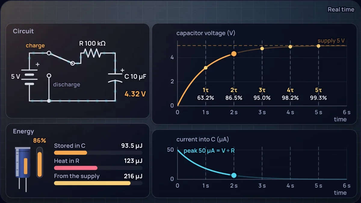
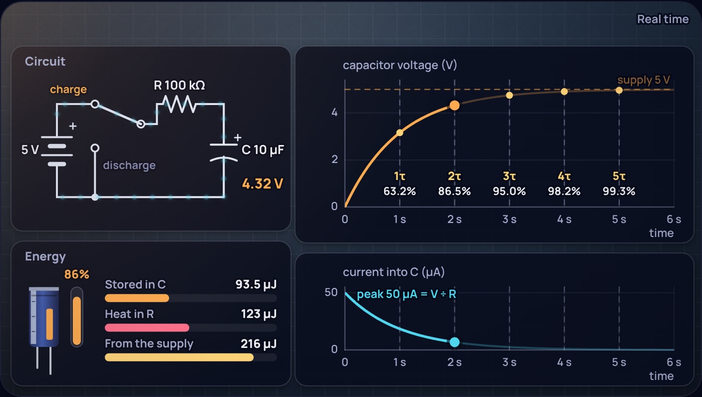
Charge a 10 µF capacitor to 5 V from a battery through a 100 kΩ resistor and the battery delivers 250 µJ of energy. The capacitor ends up holding 125 µJ. The other 125 µJ warms the resistor. Swap in a 1 kΩ resistor, or a 1 MΩ one, and the split stays exactly the same: half stored, half heat.
That rule surprises people because a small resistor feels as if it should waste less. This post works through why it does not, and through the other things a charging capacitor does that are easy to get wrong: how big the first rush of current is, how long charging and discharging really take, and why a capacitor that has sat for "five time constants" can still bite. Every number comes from the capacitor charging simulator, which puts a battery, a two-way switch, a resistor and a capacitor on the bench and tracks voltage, current and energy as you flip the switch.
What happens in the first instant after the switch closes?
An empty capacitor has no voltage across it. When the switch connects it to the battery through R, the capacitor cannot jump to 5 V, because its voltage is set by the charge it holds, , and charge takes time to flow in. So at t = 0 the whole supply voltage sits across the resistor, and the current is as large as it will ever be:
As charge flows in, the capacitor voltage rises, the voltage left across the resistor shrinks, and the current falls. Each of those follows from the other, which is why the curve is exponential. Solving Kirchhoff's voltage law, , gives the two equations the simulator draws:
The product RC has units of seconds and is called the time constant τ. With 100 kΩ and 10 µF it is exactly one second. The RC time constant post goes through why one τ lands at 63.2%, which is 1 − 1/e.
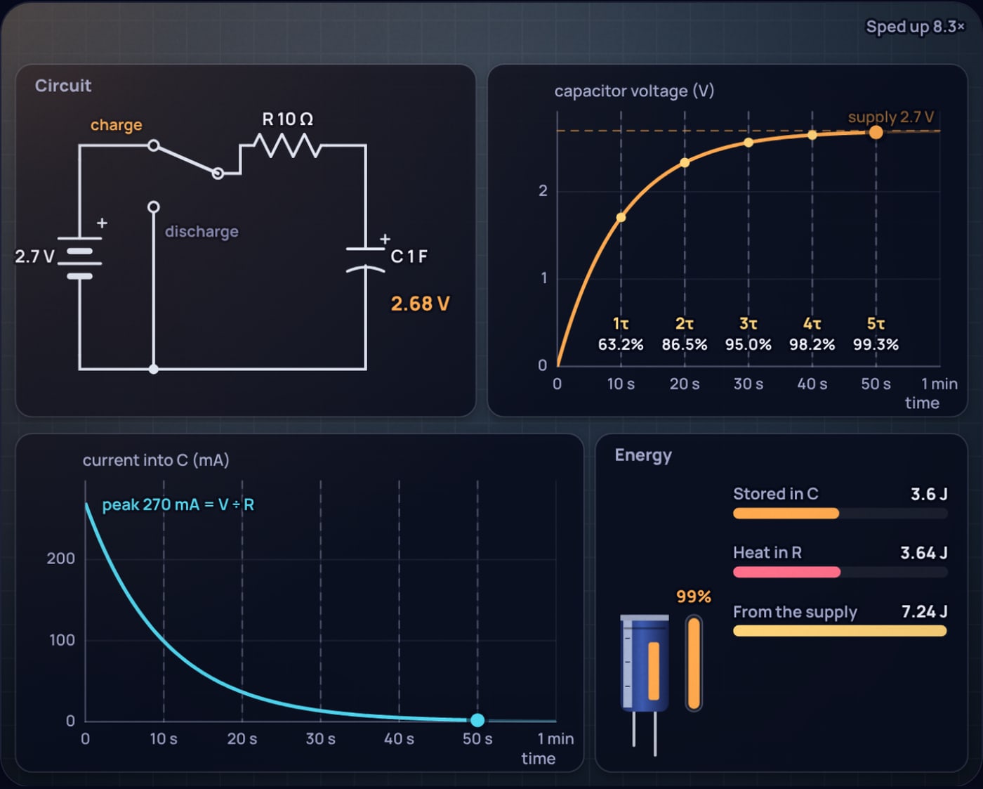
The peak current matters more than its small size here suggests. With a 1 F supercapacitor charged from 2.7 V through 10 Ω, the first instant draws 270 mA, and with no resistor at all only the wiring and the capacitor's internal resistance limit it. That inrush is why chargers for large capacitors limit current deliberately.
How long does a capacitor take to charge?
Because the curve slows down as it goes, "fully charged" is a choice, not an event. The standard landmarks, which hold for every R and C, are:
| Time after the switch | Charging (% of supply) | Discharging (% left) | Current (% of peak) | Energy stored (% of full) |
|---|---|---|---|---|
| 0.69τ | 50.0% | 50.0% | 50.0% | 25.0% |
| 1τ | 63.2% | 36.8% | 36.8% | 40.0% |
| 2τ | 86.5% | 13.5% | 13.5% | 74.8% |
| 3τ | 95.0% | 5.0% | 5.0% | 90.3% |
| 4τ | 98.2% | 1.8% | 1.8% | 96.4% |
| 5τ | 99.3% | 0.7% | 0.7% | 98.7% |
Five time constants, 99.3%, is the usual engineering answer for "charged". The last column is worth a look: stored energy goes with the square of the voltage, so at one τ, when the voltage is 63.2% of the way up, the capacitor holds only 40% of its final energy. Half the voltage is a quarter of the energy.
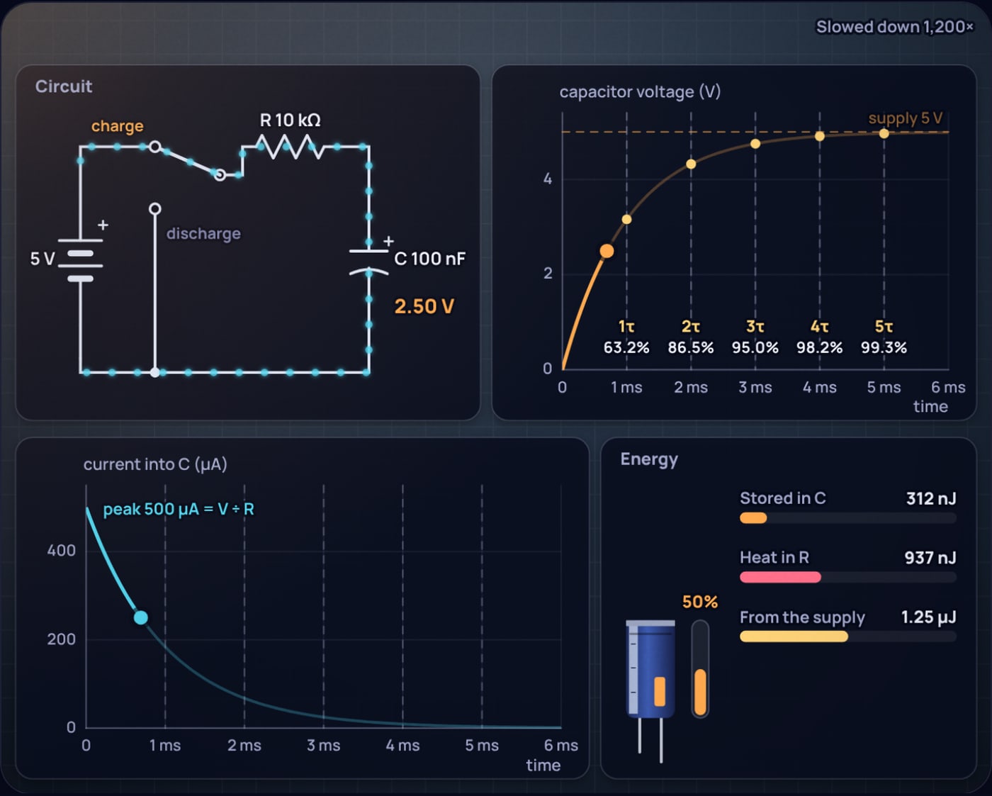
For the 100 kΩ, 10 µF circuit, the numbers are easy: half charge after 0.69 s, 90% after 2.30 s, effectively full after 5 s. A button debounce filter with 10 kΩ and 100 nF does the same thing a thousand times faster, crossing half the supply after 0.69 ms. A 555 timer uses the same curve between one third and two thirds of its supply, which is where the 0.693 in the 555 astable formula comes from.
Why is half the energy lost when charging a capacitor?
Here is the bookkeeping. The supply holds its voltage V the whole time, and over a full charge it pushes a total charge through the circuit. Energy delivered by a source is charge times voltage, so the supply gives up .
The capacitor stores less, because its voltage started at zero. The first coulomb went in when the capacitor was at 0 V, the last at nearly V. Adding up along the way gives the familiar result:
The difference has to go somewhere, and the only place is the resistor. You can check it directly by adding up the resistor's heat, , over the whole charge:
Heat in the resistor during a full charge, using :
R cancels. For 10 µF at 5 V: supplied , stored 125 µJ, heat 125 µJ.
That cancellation is the whole story. A small resistor gives a large current for a short time; a large resistor gives a small current for a long time. The heat integrates to the same total either way. HyperPhysics states the same result: half the energy drawn from the battery is dissipated in the resistance, independent of its size.
The heat is also front-loaded, because the current is largest at the start. In the simulator's energy card, the resistor has already taken 86.5% of its final share after one time constant, while the capacitor has only 40% of its final energy. That is why the "Heat in R" bar runs ahead of "Stored in C" in Figure 1, and the two only meet near the end.
What does that mean for a supercapacitor?
The 50% rule becomes practical once the capacitor is big. A 1 F supercapacitor rated 2.7 V, such as the Eaton HV0810-2R7105-R, stores about 3.6 J when full. Charging it from a fixed 2.7 V source through a resistor costs another 3.6 J as heat, no matter which resistor you choose.
1 F supercapacitor, 2.7 V supply, 10 Ω series resistor:
A quarter-watt resistor would be overloaded for the first few seconds even though the average power over 50 s is only about 0.07 W.
The only ways around the loss are to avoid putting a large voltage across a resistance in the first place. Charging in many small voltage steps loses less, because each step only drops a small voltage across R. A switching converter or a constant-current charger does this continuously, using an inductor to move energy instead of burning the difference. That is why serious supercapacitor chargers are switching designs. The part's own internal resistance, about 0.2 Ω for this cell, still takes its share.
Does a capacitor lose energy when it discharges too?
Yes, all of it, by design. Flip the switch to discharge and the capacitor becomes the source, pushing current backwards through the same resistor. The voltage falls as : 36.8% after one τ, 13.5% after two, 0.7% after five. Every joule it held ends up as heat in R.
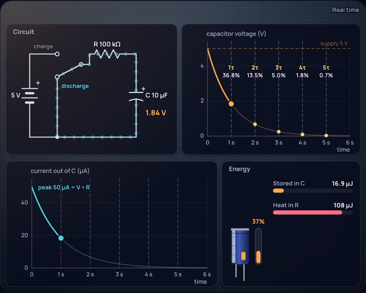
Over a full charge and discharge cycle, then, the resistor has turned the whole into heat. That is the energy cost of every RC timer tick and every logic gate that charges and empties the capacitance of a wire. The same RC also sets a filter's cutoff frequency, , covered in the RC low-pass filter post.
Is a capacitor safe after five time constants?
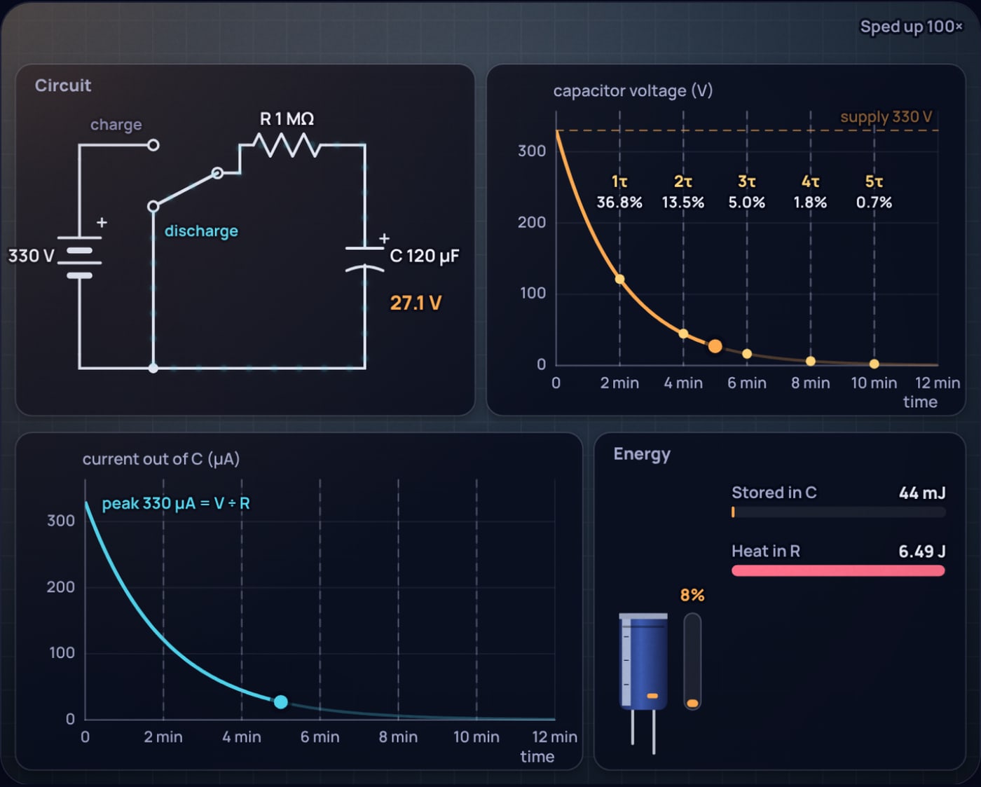
Five τ leaves 0.7% of the starting voltage. On a 5 V circuit that is 34 mV, which is nothing. On a camera flash capacitor it is a different story. Small cameras typically use a photoflash capacitor of 80 to 240 µF charged to 180 to 330 V. Take 120 µF at 330 V, discharged through a 1 MΩ bleed resistor.
120 µF flash capacitor at 330 V with a 1 MΩ bleeder:
So the bleeder does its job, but slowly: three and a half minutes before the voltage drops below 60 V, a level often used as a conservative limit for ripple-free DC that is safe to touch in harsher conditions. The rule of thumb to take away is to count time constants from the voltage you need to reach, not from a fixed five. A bleeder resistor also only helps if it is actually connected and intact; the bleeder resistor literature notes that a failed one can leave dangerous voltages on capacitors for days. Measure before touching.
What does the simple RC model leave out?
The simulator's circuit is ideal, and real parts shift the numbers in predictable ways:
- Series resistance you did not draw. The battery, switch, wires and the capacitor's own equivalent series resistance all add to R. They lengthen τ slightly and take part of the heat, but the total heat is still ½CV².
- Leakage. Electrolytic capacitors leak a little current, so one charged through 10 MΩ may settle short of the supply.
- Tolerance. Electrolytics and supercapacitors are commonly −10% to +30% or ±20%, so a real τ can be that far off before anything else.
- Dielectric absorption. A large capacitor that was shorted briefly can recover part of its voltage afterwards, another reason to measure rather than assume.
Try it yourself
Open the capacitor charging simulator and set any R and C. Watch the energy card while it charges and note how "Heat in R" leads "Stored in C" early on and then meets it. Then move R across three decades and check that the final heat never changes. Load the flash capacitor preset and see how long it takes to reach a voltage you would be willing to touch.
Sources
- HyperPhysics, Energy stored on a capacitor: half the energy from the battery is dissipated in the resistance, independent of its value.
- Wikipedia, RC time constant: 63.2% after τ, 36.8% on discharge, 99.3% at 5τ, and the cutoff frequency relation.
- DigiKey listing, Eaton HV0810-2R7105-R supercapacitor: 1 F, 2.7 V, 200 mΩ ESR, −10% to +30% tolerance.
- Wikipedia, Photoflash capacitor: 80 to 240 µF and 180 to 330 V in small cameras.
- Wikipedia, Bleeder resistor: purpose, and dangerous voltages retained when a bleeder fails.
- Wikipedia, Extra-low voltage: 120 V ripple-free DC limit, with 60 V specified for harsher conditions.
Frequently asked questions
Why is half the energy lost when charging a capacitor?
The supply pushes the whole charge Q = CV through at its full voltage V, so it delivers CV squared. The capacitor stores only half of that, one half CV squared, because each bit of charge arrived while the capacitor voltage was still lower than the supply. The other half is turned into heat in the resistance in series.
Does a bigger resistor waste less energy when charging a capacitor?
No. A bigger resistor makes the current smaller and the charge slower, but the current flows for longer, and over a full charge the heat comes to exactly one half CV squared for any resistance. The resistor value changes how fast the energy is lost, not how much.
How long does a capacitor take to charge?
About five time constants, 5 times R times C, to reach 99.3 percent of the supply voltage. With 100 kilohms and 10 microfarads the time constant is 1 second, so the capacitor is effectively full after about 5 seconds. It is at 63.2 percent after one time constant.
What is the current when a capacitor starts charging?
At the instant the switch closes the capacitor has no voltage across it, so the whole supply voltage sits across the resistor and the current is V divided by R. It then falls by the same exponential as the voltage rises: 36.8 percent of the peak after one time constant and 0.7 percent after five.
How long does a capacitor hold a dangerous charge?
It decays by the time constant of whatever discharges it. A 120 microfarad flash capacitor at 330 V with a 1 megohm bleed resistor has a 2 minute time constant and takes about 3.4 minutes to fall below 60 V. Without a bleed path it can hold charge far longer, so measure the voltage before touching.
 555 Timer Frequency Formula: Where 1.44 Comes From
 ADC Resolution vs Accuracy: ENOB, INL and the Reference
