How to Choose R and C for a Low-Pass Filter (With Examples)
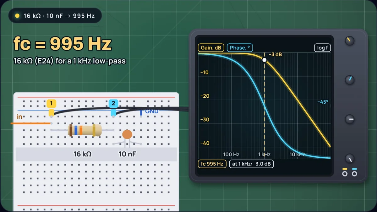
The formula for an RC filter fits on a sticky note: . The problem in practice runs the other way. You know the cutoff you want, and there are endless pairs of R and C that give it, almost none of which you can buy. This post goes through choosing the pair: which part to fix first, what range of resistance is sensible, how to round to standard values, and how far the cutoff can wander once tolerances are counted.
The RC filter calculator does each step: give it a cutoff and one part, and it solves the other, rounds it to E12, E24 or E96 and draws the Bode plot. Every number below comes from it. What the −3 dB point means, and how the next stage shifts it, is covered in RC low-pass filter cutoff.
Step 1: decide where the cutoff goes
A single RC stage is gentle. Its gain is , so a signal at twice the cutoff still gets through at 45% of its amplitude, and one at ten times the cutoff at 10% (−20 dB). That sets the first rule: the cutoff needs to sit well below whatever you want to remove, not just below it.
How low must the cutoff be to cut 50 Hz hum by 20 dB?
Anything you want to keep must then be slower than about 5 Hz. If it is not, one RC stage is the wrong tool, and you need more stages or an active filter.
Going the other way, a signal at the cutoff is already down to 70.7%. If you want to pass a 1 kHz tone almost untouched, put the cutoff several times higher, not at 1 kHz.
Step 2: choose a sensible resistance range
Only the product RC sets the cutoff, so 1.6 kΩ with 100 nF, 16 kΩ with 10 nF and 160 kΩ with 1 nF are the same 1 kHz filter on paper. On the bench they are not. The resistor sits between whatever drives the filter and whatever reads it:
- Too small, and the filter draws real current from its source. A 1 kΩ resistor across a 5 V step draws 5 mA the moment the step arrives, and a source with its own resistance simply adds it to R.
- Too large, and leakage and loading take over. The ATmega328P datasheet lists up to 1 µA of input leakage on an I/O pin. Through 16 kΩ that is at most 16 mV of error; through 1.6 MΩ, up to 1.6 V.
That leaves a comfortable range of roughly 1 kΩ to 100 kΩ for most circuits. The same datasheet says its ADC is optimised for sources of about 10 kΩ or less, which makes 10 kΩ a natural default in front of a microcontroller.
The table shows how the capacitor choice moves R for a few cutoffs. Cells in a sensible range are the combinations worth building.
| Cutoff | with 100 nF | with 10 nF | with 1 nF |
|---|---|---|---|
| 10 Hz | 160 kΩ | 1.6 MΩ | 16 MΩ |
| 100 Hz | 16 kΩ | 160 kΩ | 1.6 MΩ |
| 1 kHz | 1.6 kΩ | 16 kΩ | 160 kΩ |
| 10 kHz | 160 Ω | 1.6 kΩ | 16 kΩ |
Values are the nearest E24 resistor; each gives a cutoff 0.5% below the target. For 10 Hz the useful pair is 10 kΩ with a microfarad or more, which is the ADC example further down.
Step 3: fix the capacitor, then solve for the resistor
Fix C first. Vishay's decade table pairs each value series with a tolerance: E12 for ±10%, E24 for ±2% and ±5%, E96 for ±1%. Ceramic capacitors are looser parts: KEMET's leaded catalogue lists its C0G capacitors at ±5%, ±10% or ±20% for most values and its X7R ones at ±10% or ±20%, so coarse steps are all they need. Resistors at ±1% come in 96 values per decade. Matching a fine-grained part to a coarse one gets much closer than the reverse.
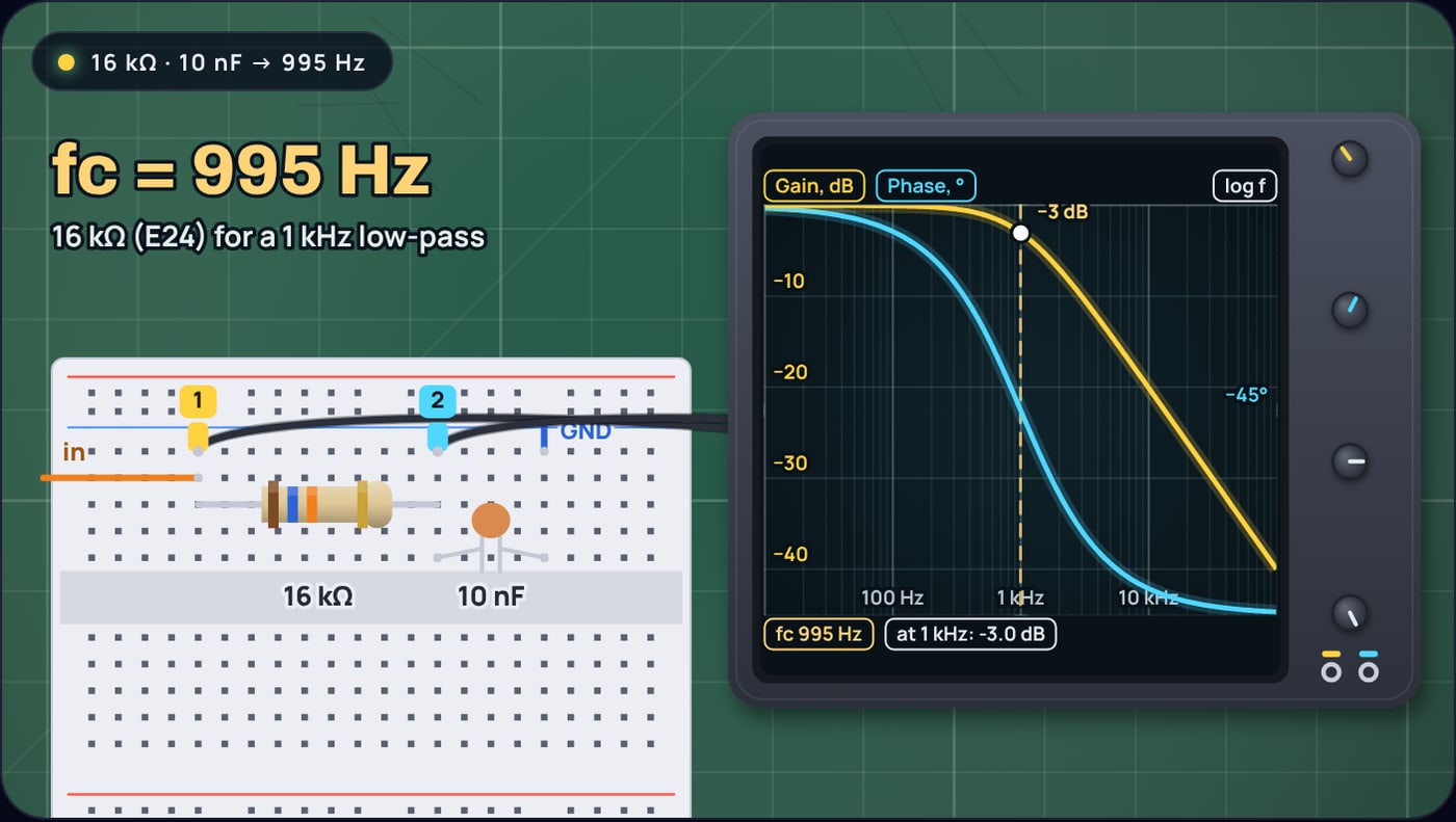
Example 1: a 1 kHz low-pass with a 10 nF capacitor
E24 and E96 both land within 1%, which is less than either resistor's own tolerance. E12 misses by 6%, because its steps are about 20% apart. If E12 is all you have, a combination such as 15 kΩ plus 1 kΩ in series gets closer.
Step 4: check how far tolerances move the cutoff
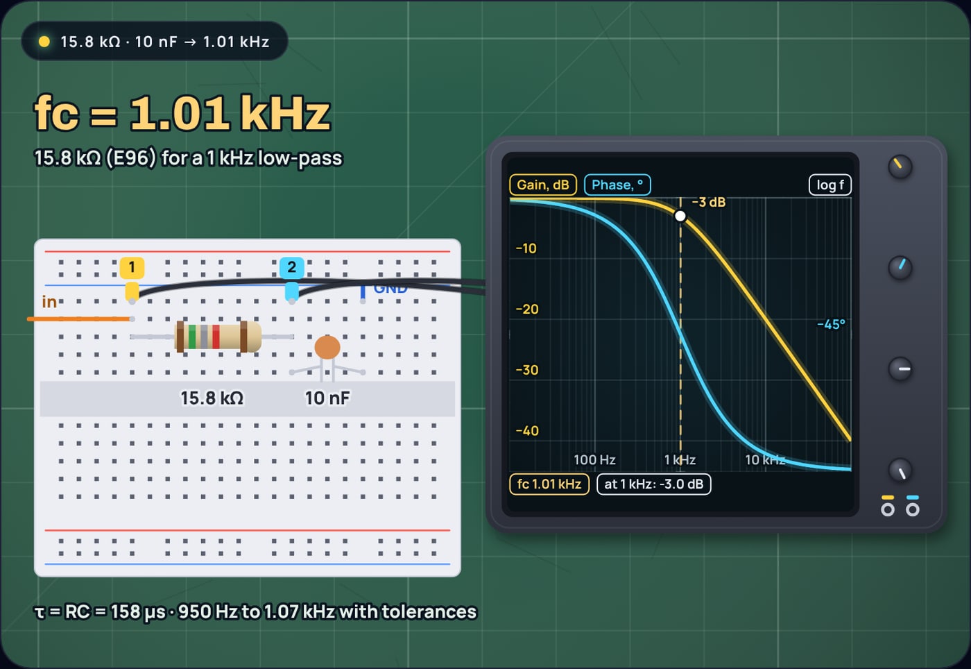
The cutoff is inversely proportional to both R and C, so their errors add. With both parts at the low ends of their tolerance the cutoff rises; at the high ends it falls.
Spread for the 1 kHz filter (16 kΩ, 10 nF)
That is a 5% resistor and a 5% capacitor. With a 10% capacitor the range widens to 861 Hz to 1.16 kHz.
Rounding to the nearest E24 value cost half a percent. The tolerances cost ten times that. For most filters this is fine, since the response is so gradual that a 10% shift in the corner changes little. Where it is not fine, tighten the capacitor first: a 1% resistor with a 10% capacitor is still a 10% filter.
Step 5: pick the right kind of capacitor
The tolerance printed on a capacitor is not the whole story. KEMET's ceramic capacitor catalogue gives the EIA classes:
- C0G (NP0), class I: 0 ± 30 ppm per °C from −55 to +125 °C, and not affected by voltage, frequency or time.
- X7R, class II: up to ±15% change over −55 to +125 °C, and affected by temperature, voltage, frequency and time.
Murata adds that high-dielectric types such as X7R lose capacitance when a DC voltage is applied, the DC bias effect, while C0G types do not. In a low-pass filter the capacitor sits at the output voltage, so an X7R part's value can depend on the signal it is filtering. For a 10 nF part, C0G is easy to find and is the safe choice. Above a microfarad, the choice is usually X7R or an electrolytic, and the cutoff should be treated as approximate.
Example 2: a 10 Hz filter in front of an ADC
A sensor wired to a microcontroller picks up mains hum. With R fixed at 10 kΩ, the source impedance the ATmega328P datasheet asks for, solve for C:
10 Hz with 10 kΩ
To reach −20 dB at 50 Hz, as in step 1, the cutoff has to drop to about 5 Hz: 3.3 µF gives 4.82 Hz and −20.4 dB.
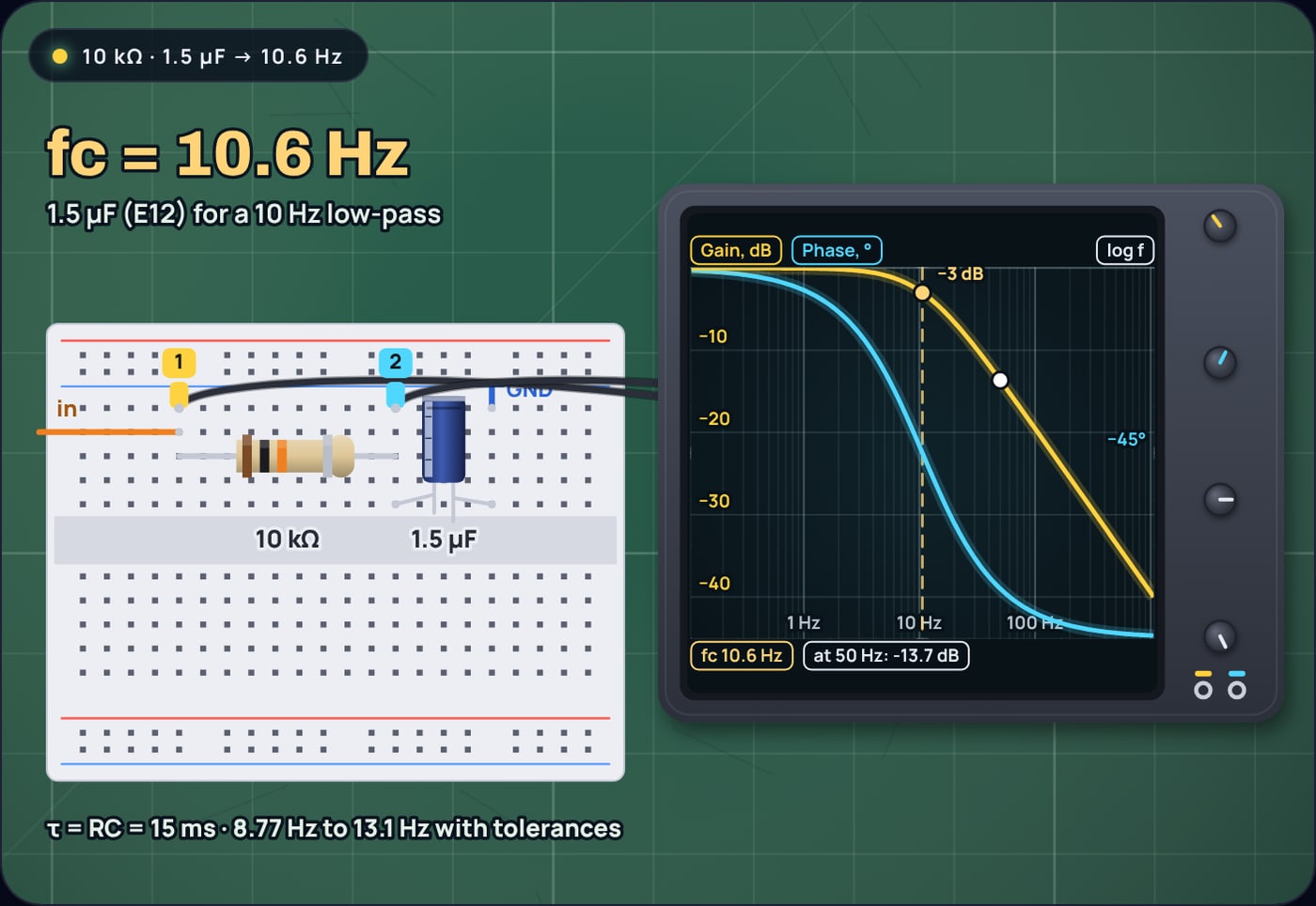
There is a bonus here. The ATmega328P samples through a 14 pF sample-and-hold capacitor. With 1.5 µF sitting on the pin, each sample takes its charge from the big capacitor and moves its voltage by about 14 pF ÷ 1.5 µF, under one part in 100,000. The filter capacitor makes the source look stiff to the ADC.
Example 3: a coupling capacitor is a high-pass filter
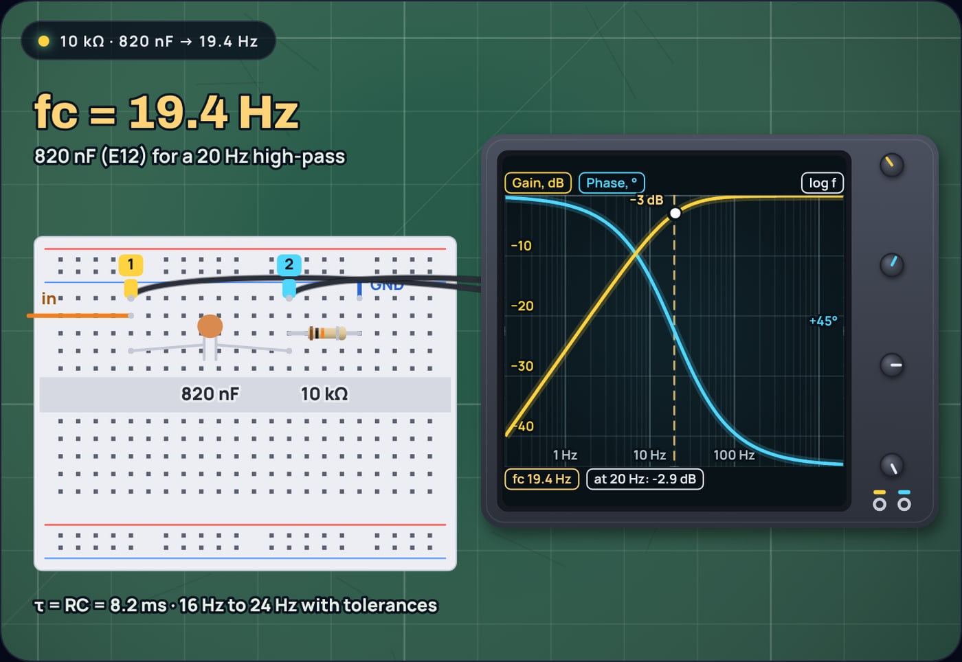
Swap R and C and the same formula gives a high-pass filter. The commonest one is not drawn as a filter at all: a capacitor in series with a signal, feeding an input with some resistance to ground. Suppose the input is 10 kΩ and the bass must reach down to 20 Hz:
20 Hz high-pass into 10 kΩ
For a high-pass corner, rounding the capacitor up is the safe direction: it moves the corner lower, further out of the way.
Example 4: check the filter in the time domain
The same RC sets how fast the output follows a change. The time constant is , and after a step the output covers 63% of the way in one τ and 99.3% in five. If the filter smooths a signal that switches, such as a button or a slow digital line, the time constant matters more than the cutoff.
A 100 Hz square wave through 10 kΩ and 100 nF
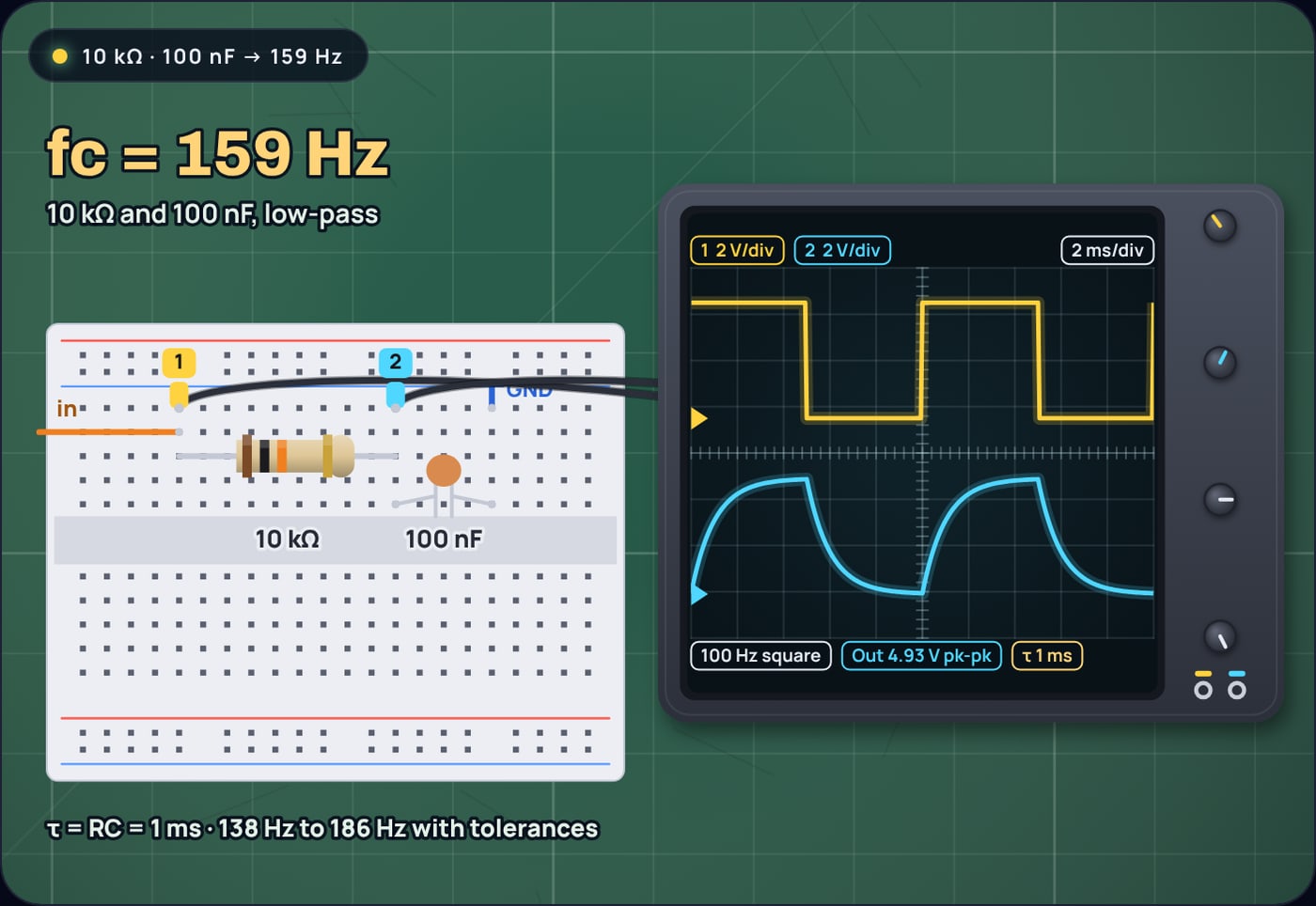
The step response is covered in more depth in the RC time constant and the 63% rule.
A short checklist
- Put the cutoff where the unwanted signal is at least several times higher (low-pass) or lower (high-pass).
- Pick C so that R falls between about 1 kΩ and 100 kΩ.
- Solve R = 1/(2π fc C) and round to E24, or E96 for 1% parts.
- Work out the tolerance spread, and tighten the capacitor first if it is too wide.
- Use C0G where you can, and remember that X7R loses value under DC bias.
- Count the source resistance in R and keep the load well above R, or buffer the output.
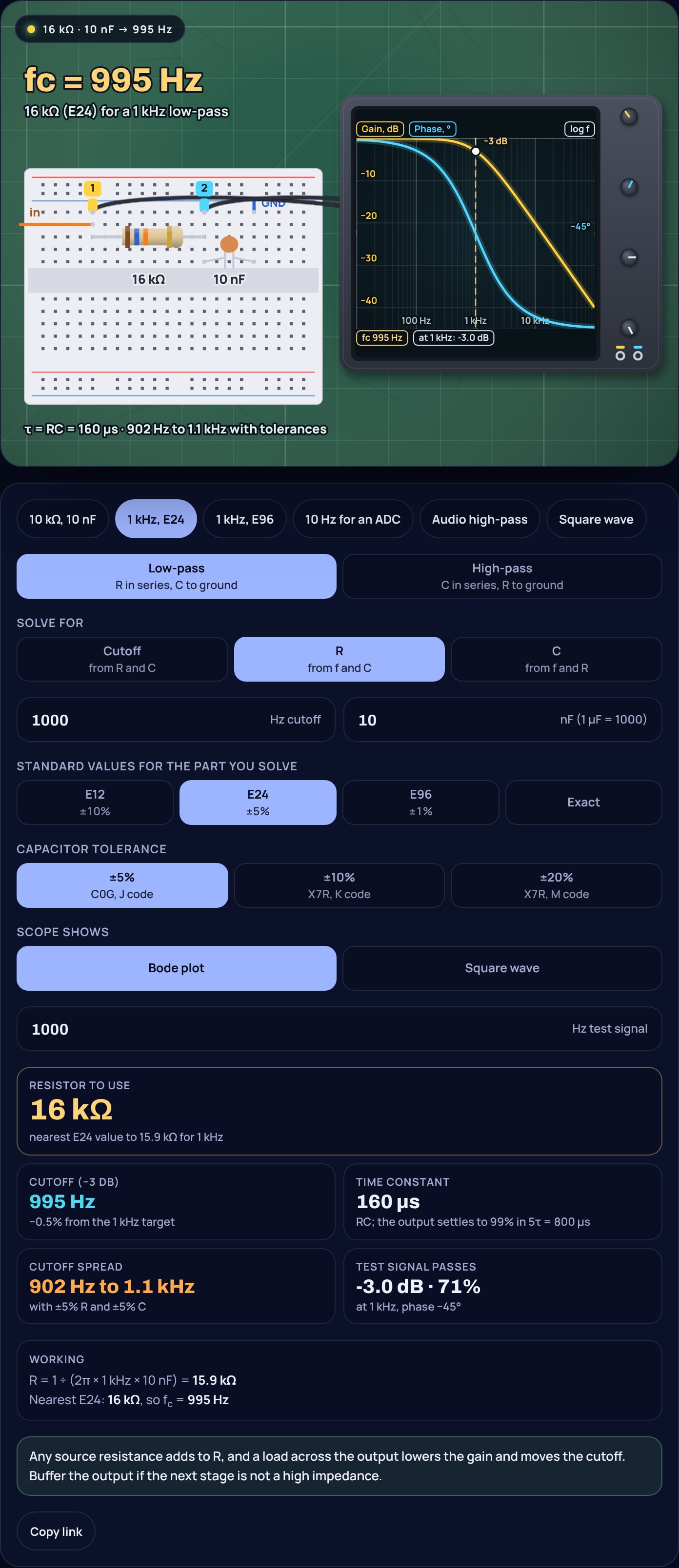
To design your own, open the RC filter calculator, choose low-pass or high-pass, pick whether to solve for R, C or the cutoff, and switch the scope between the Bode plot and a square wave to see what the filter does to a real signal.
Sources
- Vishay Dale, "Standard Electronic Decade Value Tables" (document 31001) (E12 for ±10%, E24 for ±2% and ±5%, E96 for ±1%; the values in each series)
- KEMET, multilayer ceramic capacitors, axial and radial leaded (C320 series catalogue) (EIA class I and II; C0G 0 ± 30 ppm/°C; X7R ±15% from −55 to +125 °C; tolerances offered, C0G ±5, 10, 20% and X7R ±10, 20%)
- Murata, FAQ on the DC bias characteristic of ceramic capacitors (high-dielectric types such as X7R lose capacitance with DC voltage; C0G has no DC bias characteristic)
- Microchip, ATmega328P automotive datasheet (ADC optimised for sources of about 10 kΩ or less, low-pass filter advised before the ADC, 14 pF sample-and-hold capacitor, 1 µA maximum I/O pin input leakage)
- Virtual Labs, IIT Kharagpur, "RC Frequency Response" theory (RC low-pass and high-pass filters, cutoff frequency)
Frequently asked questions
How do I choose R and C for a low-pass filter?
Decide the cutoff, pick a capacitor value that puts R between about 1 kΩ and a few hundred kΩ, then calculate R = 1/(2π fc C) and round it to a standard value. For 1 kHz with 10 nF, R = 15.9 kΩ; the E24 value 16 kΩ gives 995 Hz.
Should I choose R or C first?
C first. Ceramic capacitors are commonly ±5% to ±20% parts, and the value series that match those tolerances (E12 for ±10%) have few values per decade. Resistors come in E96 at ±1%, so a resistor can be matched to the capacitor much more closely than the other way round.
What resistor value is best for an RC filter?
Roughly 1 kΩ to 100 kΩ for most circuits. Below 1 kΩ the filter loads its source; well above 100 kΩ, input leakage and the load start to matter. An ATmega328P ADC, for example, wants a source of about 10 kΩ or less and has up to 1 µA of pin leakage.
Which capacitor type should I use in an RC filter?
C0G (NP0) ceramic where you can: it changes by at most 30 ppm per °C and does not lose capacitance with DC voltage. X7R can change by up to 15% over temperature and loses capacitance under DC bias, which moves the cutoff.
How accurate is an RC filter cutoff?
Only as accurate as the parts. A 1 kHz filter from a 5% resistor and a 5% capacitor lands anywhere from about 900 Hz to 1.1 kHz; with a 10% capacitor, 860 Hz to 1.16 kHz. The resistor rounding adds less than 1% in E24.