How do you calculate an RC filter?
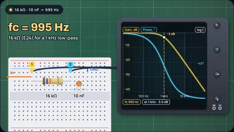
The cutoff of an RC filter is fc = 1 ÷ (2πRC). 10 kΩ and 10 nF give 1.59 kHz. For a 1 kHz low-pass with a 10 nF capacitor, R = 15.9 kΩ; the nearest E24 resistor, 16 kΩ, puts the cutoff at 995 Hz.
What the −3 dB point means and how loading moves it is covered in RC low-pass filter cutoff; the step response is in the RC time constant. For picking parts, with worked examples, see how to choose R and C for a low-pass filter.
Key results from the calculator
- 10 kΩ and 10 nF: 1.59 kHz, time constant 100 µs.
- 1 kHz with 10 nF: 16 kΩ (E24, −0.5%), 15.8 kΩ (E96, +0.7%) or 15 kΩ (E12, +6.1%).
- 10 Hz with 10 kΩ: 1.5 µF gives 10.6 Hz and cuts 50 Hz hum to 21%.
- Tolerances: with a 5% resistor and a 10% capacitor, a 1.59 kHz filter can land anywhere from 1.38 kHz to 1.86 kHz.
Six filters
Each example loads the filter type, the part being solved, the value series and the test signal.
10 kΩ and 10 nF
Textbook values1 ÷ (2π × 10,000 × 10 × 10⁻⁹) = 1.59 kHz. A 1 kHz signal passes at 85% and lags by 32°.
A 1 kHz low-pass with a 10 nF capacitor
Solve for RThe exact resistor is 15.9 kΩ. The nearest E24 value, 16 kΩ, gives 995 Hz, −0.5% from target and well inside a 5% resistor's own tolerance.
The same filter with 1% resistors
E96 seriesE96 offers 15.8 kΩ, +0.7% off. The tighter resistor narrows the spread to 950 Hz to 1.07 kHz with a 5% capacitor; the capacitor now dominates.
A 10 Hz filter in front of an ADC
Solve for CWith R fixed at 10 kΩ, the source impedance the ATmega328P datasheet asks for, C = 1.59 µF. E12 gives 1.5 µF, so 10.6 Hz; 50 Hz mains hum is cut by 13.7 dB.
A coupling capacitor into a 10 kΩ input
High-passA series capacitor and the next stage's 10 kΩ input form a high-pass filter. For a 20 Hz corner, C = 796 nF; the E12 820 nF gives 19.4 Hz.
A 100 Hz square wave through 10 kΩ and 100 nF
Time domainThe time constant is 1 ms and each half cycle lasts 5 ms, five time constants, so the output just about reaches each level before the input flips.
Resistor for a 10 nF capacitor, by cutoff
| Cutoff | Exact R | E24 | Cutoff with E24 | E96 | Cutoff with E96 |
|---|---|---|---|---|---|
| 100 Hz | 159 kΩ | 160 kΩ | 99.5 Hz | 158 kΩ | 101 Hz |
| 300 Hz | 53.1 kΩ | 51 kΩ | 312 Hz | 53.6 kΩ | 297 Hz |
| 1 kHz | 15.9 kΩ | 16 kΩ | 995 Hz | 15.8 kΩ | 1.01 kHz |
| 3 kHz | 5.31 kΩ | 5.1 kΩ | 3.12 kHz | 5.36 kΩ | 2.97 kHz |
| 10 kHz | 1.59 kΩ | 1.6 kΩ | 9.95 kHz | 1.58 kΩ | 10.1 kHz |
| 30 kHz | 531 Ω | 510 Ω | 31.2 kHz | 536 Ω | 29.7 kHz |
Same for low-pass and high-pass. For another capacitor, scale R inversely: 100 nF needs a tenth of these resistances.
How the calculator works
Cutoff: fc = 1 ÷ (2πRC), where the capacitor’s reactance equals R.
Solving: R = 1 ÷ (2π fc C), or C = 1 ÷ (2π fc R), then rounded to the nearest value in the chosen series (E12, E24 or E96, from Vishay’s decade table).
Response: gain 1 ÷ √(1 + (f/fc)²) for low-pass and (f/fc) ÷ √(1 + (f/fc)²) for high-pass; phase −arctan(f/fc), plus 90° for high-pass.
Spread: the cutoff with both parts at the ends of their tolerances: the series tolerance for R (E12 10%, E24 5%, E96 1%) and the one you pick for C.
What the model leaves out
- Source and load: the source resistance adds to R, and a load across the output lowers the gain and raises the cutoff of a low-pass.
- Capacitor voltage and temperature: X7R ceramics lose capacitance with DC voltage and change up to ±15% over temperature; C0G does neither.
- Parasitics: at very high frequencies the capacitor’s own inductance and the board’s capacitance take over.
- Higher orders: one RC stage rolls off at 20 dB per decade; steeper filters need more stages or active designs.
Common misconceptions
"Above the cutoff, nothing gets through." At twice the cutoff a first-order filter still passes 45%; at ten times, 10%.
"Any R and C with the right product will do." The product sets the cutoff, but R decides how hard the source works and how much the load matters.
"The calculated value is what you get." A 10% capacitor moves the cutoff by about 10% before the resistor is even counted.
Frequently asked questions
What is the formula for an RC filter cutoff?
fc = 1 ÷ (2πRC), with R in ohms and C in farads. 10 kΩ and 10 nF give 1.59 kHz.
How do I pick R and C for a cutoff?
Choose the capacitor first, since it comes in fewer values, then R = 1 ÷ (2π fc C) and round to a standard resistor. For 1 kHz with 10 nF: 16 kΩ in E24.
Is the formula the same for a high-pass filter?
Yes. Swapping R and C changes which side of the cutoff passes, not where the cutoff is.
What is the time constant of an RC filter?
τ = RC, which equals 1 ÷ (2π fc). For 10 kΩ and 10 nF it is 100 µs; a step reaches 63% in one τ and 99% in five.
Why does my filter cut off at the wrong frequency?
Usually part tolerance, a capacitor losing value under DC voltage, or the source and load resistances adding to the circuit. Measure the parts, or buffer the filter.
Keep learning
How to Choose R and C for a Low-Pass Filter (With Examples)
Pick the capacitor first, solve for R, round to a standard value and check the tolerance spread. Worked examples for 1 kHz, a 10 Hz ADC filter and a 20 Hz coupling capacitor.

RC Low Pass Filter Cutoff Frequency: What −3 dB Means
fc = 1/(2πRC) is where the output is 0.707 of the input, half power and −45°. Why the slope there is only 10 dB/decade, and how loading moves it.

Why Is the RC Time Constant 63%? The Math of 1 − 1/e
63.2% is 1 minus 1/e, the point where an RC curve would have finished if it kept its starting slope. Why e appears, and why 5τ is not always enough.