How do you use a transistor as a switch?
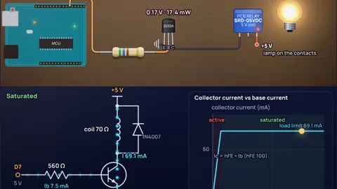
Put an NPN transistor between the load and ground, connect the microcontroller pin to its base through a resistor, and size that resistor so the base gets about one tenth of the load current. For a 5 V relay with a 70 Ω coil on an Arduino, the coil draws 69.1 mA, so the base needs about 6.91 mA and the resistor is (5 − 0.8) ÷ 6.91 mA ≈ 608 Ω. Use 560 Ω. The transistor then saturates: only 0.17 V across it and 17.4 mW of heat.
The ratio of collector current to base current you design for is called the forced beta. The datasheet gain (hFE) of a PN2222A is at least 100, so it is tempting to supply only a hundredth of the load current. Do that and any part with a lower gain, or a slightly hotter room, leaves the transistor half on, dropping volts and getting hot. The slider in the simulation lets you see that happen. The forced beta post has the theory, and this page is the calculator that goes with it.
Key results from the simulation
- Relay on an Arduino Uno: PN2222A, 560 Ω base resistor, 7.5 mA from the pin, 69.1 mA through the coil, 0.17 V across the transistor, 17.4 mW of heat.
- Same relay on an ESP32 (3.3 V pin): the resistor drops to 330 Ω because there is less voltage to work with, and the base still gets 7.58 mA.
- Starve the base and it heats up: with a forced beta of 200 the motor gets 127 mA instead of 228 mA, the transistor drops 2.5 V and dissipates 313 mW, about 50% of its rating.
- A logic-level MOSFET has no base current: an IRLZ44N switches a 499 mA LED strip with 0.012 V across it and 6.24 mW of loss, at 25 mΩ with 5 V on the gate.
- Check the ratings: a BC547 is rated for 100 mA, so it cannot switch a 232 mA motor, and a single pin should not have to supply much more than 20 mA of base current.
Six common setups, worked through
Each section loads a real circuit: the load, the transistor, the board and the forced beta. Numbers come from datasheet values for the parts named, with the model limits listed further down.
A 5 V relay from an Arduino pin
PN2222A, forced beta 10A common blue 5 V PCB relay (SRD-05VDC) has a 70 Ω coil, so it wants 71.4 mA at 5 V. That is more than an Arduino pin should supply, which is why the transistor is there. With 0.17 V across the saturated PN2222A, the coil current is 69.1 mA.
For a forced beta of 10 the base needs 6.91 mA. The Uno pin sits at 5 V and the base-emitter junction takes about 0.8 V, which leaves 4.2 V across the resistor: 4.2 ÷ 6.91 mA = 608 Ω. The next standard value down is 560 Ω, which gives 7.5 mA. The 1N4007 across the coil is not optional: it gives the coil current a path when the transistor turns off, see the flyback diode post.
The same relay from a 3.3 V ESP32
PN2222A, 3.3 V driveKeep the relay on the 5 V supply and drive only the base from the 3.3 V pin. The transistor does the level shifting for free. With 3.3 − 0.8 = 2.5 V across the base resistor, 6.91 mA of base current needs 362 Ω, so use 330 Ω.
The coil current is the same 69.1 mA because it depends only on the 5 V supply and the coil. Many cheap relay modules also work this way, though some have an optocoupler input that needs more than 3.3 V to trigger reliably.
A small DC motor: watch the pin current
PN2222A, forced beta 20A small hobby motor running at 5 V can draw around 250 mA. Through a saturated PN2222A it gets 228 mA. At a forced beta of 10 the base would need 23.3 mA, more than you want from one Arduino pin. Relaxing to a forced beta of 20 brings it to 12.7 mA with a 330 Ω resistor, and the PN2222A, with a gain of at least 100 at these currents, still saturates.
The transistor drops 0.43 V and dissipates 109 mW, comfortable for a TO-92 part rated at 625 mW. A motor is inductive, so it gets a flyback diode too. To reverse the motor you need an H-bridge instead, which the H-bridge post explains.
What goes wrong when you divide by hFE
PN2222A, forced beta 200Size the base resistor from a gain of 200 (a number you might read off a typical curve) and you get 3.3 kΩ, which gives 1.27 mA. Our PN2222A only guarantees a gain of 100, so it can pass 127 mA, not the 228 mA the motor wants.
The rest of the 5 V has to go somewhere: 2.5 V sits across the transistor, and 2.5 V × 127 mA is 313 mW of heat, half the part's rating, while the motor crawls. On the chart the operating point slides off the flat saturated line onto the sloped active line. This is the most common reason a transistor switch gets hot.
Why a BC547 cannot run a motor
BC547B, rating checkThe BC547 is a fine small-signal switch: driving an LED at 19.3 mA it needs only a 2.2 kΩ base resistor and drops 0.1 V. But its continuous collector rating is 100 mA. Ask it to run the motor at 232 mA and the model flags an overcurrent straight away.
Gain is not the problem. The small die and thin bond wires are. For anything above about 100 mA move to a PN2222A (rated 1.00 A), and above a few hundred milliamps move to a MOSFET.
A logic-level MOSFET for a 12 V LED strip
IRLZ44N, 5 V gateHalf an amp is where bipolar transistors start to hurt. A PN2222A would need 51.2 mA of base current at a forced beta of 10, beyond any pin's 40 mA absolute maximum, and would still drop 0.83 V. The IRLZ44N gate draws no steady current at all. With 5 V on the gate its on-resistance is at most 25 mΩ, so the strip gets 499 mA and the MOSFET loses just 6.24 mW.
Two resistors complete the circuit: about 220 Ω in series with the gate to tame the charging spike, and 100 kΩ from gate to ground so the MOSFET stays off while the microcontroller boots. The MOSFET gate resistor post works through the values. On a 3.3 V ESP32 it still switches (15.5 mW loss in the model) but the datasheet does not specify RDS(on) below 4 V, so pick a MOSFET rated at 2.5 V gate drive for a guaranteed result.
Every setup at a glance
| Setup | Base or gate resistor | Pin current | Load current | Across switch | Switch heat |
|---|---|---|---|---|---|
| Relay, Uno, PN2222A | 560 Ω | 7.5 mA | 69.1 mA | 0.17 V | 17.4 mW |
| Relay, ESP32, PN2222A | 330 Ω | 7.58 mA | 69.1 mA | 0.17 V | 17.5 mW |
| LED, Uno, BC547B | 2.2 kΩ | 1.95 mA | 19.3 mA | 0.1 V | 3.33 mW |
| Motor, Uno, PN2222A (β 20) | 330 Ω | 12.7 mA | 228 mA | 0.43 V | 109 mW |
| Motor, Uno, PN2222A (β 200) | 3.3 kΩ | 1.27 mA | 127 mA | 2.5 V | 313 mW |
| 12 V strip, Uno, IRLZ44N | 220 Ω + 100 kΩ | about 0 | 499 mA | 0.012 V | 6.24 mW |
Forced beta 10 unless stated. VBE is taken as 0.8 V for the PN2222A and 0.7 V for the BC547B. The load would take 357 mW (relay) and 6.00 W (strip) with a perfect switch.
How the simulation works
The load sets the current. With the transistor saturated, the collector current is (supply − load drop − VCE(sat)) ÷ load resistance. The relay is a 70 Ω coil, the motor is modelled as 20 Ω (about 250 mA at 5 V while running), the LED as 2.0 V plus 150 Ω and the strip as 24 Ω on 12 V.
The base resistor is (pin voltage − VBE) ÷ (load current ÷ forced beta), rounded down to the next E12 value so the base gets at least the target current. The simulation then solves the circuit: the transistor can carry at most hFE × Ib (hFE 100 for the PN2222A, the datasheet minimum at 150 mA, and 200 for the BC547B, its minimum at 2 mA). If that is more than the load allows, it saturates. Otherwise it sits in the active region and VCE is whatever voltage the load leaves.
VCE(sat) is a straight-line fit through the datasheet points: for the PN2222A the 0.3 V maximum at 150 mA, for the BC547B the typical 0.09 V at 10 mA and 0.2 V at 100 mA. Transistor heat is VCE × IC + VBE × IB. For the IRLZ44N the on-resistance is 25 mΩ at 5 V and 35 mΩ at 4 V from the datasheet table. Below 4 V the value is an estimate, and the curve on the chart between the threshold and about 2.5 V is a sketch, not datasheet data.
What the model leaves out
- Gain spread and temperature: hFE varies by a factor of three between parts and rises with temperature. The model uses one value per part, which is why it designs for a forced beta of 10 to 20.
- Motor start-up: a stalled or starting motor draws several times its running current for a moment. Size the transistor for the stall current, not the running current.
- Switching speed and the flyback pulse: the simulation shows steady states only. The flyback diode handles the turn-off spike, and it slows relay release, see the flyback diode post.
- VCE(sat) against forced beta: real saturation voltage creeps up as the forced beta approaches hFE. The straight-line fit holds for forced betas of about 10 to 20.
- The pin itself: a microcontroller pin sags a little under load. At 20 mA an Uno pin may sit a few hundred millivolts below 5 V, so the real base current is slightly lower.
- Thermal limits over time: dissipation is compared with the 25 °C rating. In a closed box the safe figure is lower.
Common misconceptions
“Divide the load current by hFE to get the base current.” That gives the minimum for the active region, not saturation. Use a forced beta of 10 to 20, so a tenth to a twentieth of the load current.
“Put the NPN between the supply and the load.” As a high-side switch its emitter follows the base, so the load only ever sees the pin voltage minus about 0.7 V. NPN and N-channel switches belong on the low side, between the load and ground.
“More base current is always better.” Past a forced beta of about 10 you gain almost nothing in VCE and spend pin current and turn-off time. Too much base current is mostly waste.
Frequently asked questions
How do I calculate the base resistor for a transistor switch?
Work out the load current, divide it by 10 to get the base current, then divide (pin voltage − 0.7 to 0.8 V) by that base current. For a 5 V relay with a 70 Ω coil on an Arduino: 69.1 mA ÷ 10 = 6.91 mA, and 4.2 V ÷ 6.91 mA ≈ 608 Ω. Round down to 560 Ω.
What is the difference between saturation and the active region?
In saturation the transistor has more base current than it needs, so it is fully on and only about 0.1 to 0.4 V sits across it. In the active region the collector current is limited to hFE × base current, and the transistor drops volts and gets hot. In the motor example the switch drops 0.43 V saturated and 2.5 V in the active region.
Can an Arduino pin drive a relay directly?
No. A typical 5 V relay coil draws about 71.4 mA, above the 40 mA absolute maximum of an ATmega328P pin, and the coil kicks back a voltage spike when it turns off. Use a transistor with a base resistor and a flyback diode, or a relay module that already has them.
Should I use a BJT or a MOSFET to switch a load?
Below about 100 to 200 mA a cheap NPN like the PN2222A or BC547 is simple and fine. Above that, a logic-level MOSFET wins because it needs no steady gate current and drops far less voltage: 0.012 V at half an amp for an IRLZ44N against 0.83 V for a PN2222A.
Which transistor should I use with an ESP32 or other 3.3 V board?
An NPN such as the PN2222A works well from 3.3 V: the base resistor is simply smaller, 330 Ω for a 5 V relay. For a MOSFET choose one whose datasheet gives RDS(on) at 2.5 V or 3.3 V gate drive, because many popular parts, including the IRLZ44N, are only specified from 4 V.
Keep learning
How to Drive a Relay or Motor from Arduino with a Transistor
Wire a relay, DC motor or 12 V LED strip to an Arduino or ESP32 pin with a PN2222A or a MOSFET: base resistor math, flyback diode, pin limits and heat.

Transistor Base Resistor Calculation: Use Forced Beta
Dividing load current by hFE gives a base resistor that leaves many transistors half on. Size it for a forced beta of 10, with worked 2N2222 and BC547 examples.

Relay Flyback Diode: Why You Need One and Which to Use
A relay coil can kick back 1,000 V at turn-off. A flyback diode stops it but slows contact release about 5x. Here is the math and the diode plus zener fix.

MOSFET Gate Resistor Value: How to Choose It (With Math)
The gate loop is a series RLC circuit. Choose the gate resistor for damping 0.7 to 1, then check switching loss and pin current. Worked IRLZ44N example.

How Does a Transistor Amplify? It's a Valve, Not a Source
A transistor doesn't make energy: a millivolt on the base steers current from the supply. Transconductance, gain = gm × RC, and a worked common-emitter design.