How to Drive a Relay or Motor from Arduino with a Transistor
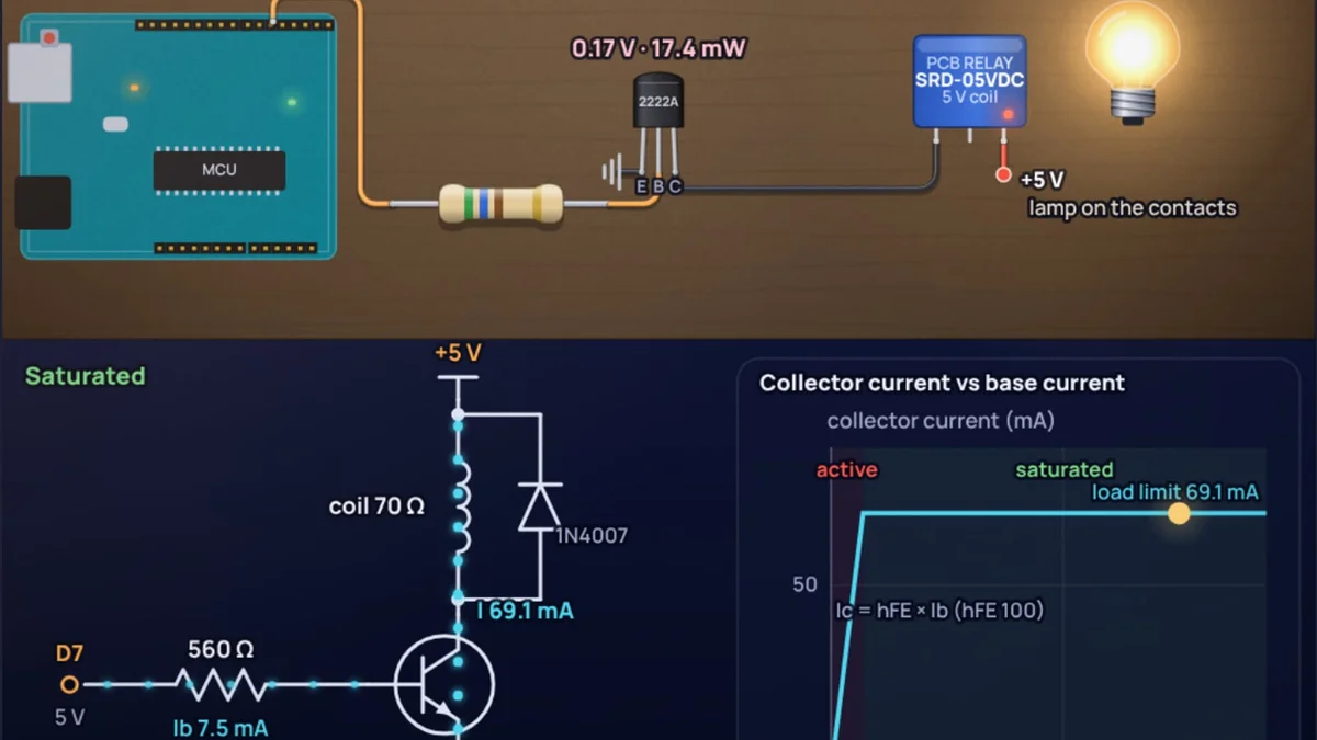
A blue 5 V relay module costs about the same as a samosa, and the bare relay on it has a 70 Ω coil. At 5 V that coil wants 71 mA. An Arduino Uno pin has an absolute maximum of 40 mA, and the coil sends back a voltage spike every time it lets go. So the most common first project in home automation, switching a lamp from an Arduino, needs one more part between the pin and the coil: a transistor.
This guide gives the complete wiring for the four loads people ask about most (a relay, a small DC motor, an LED and a 12 V LED strip), with the numbers for an Arduino Uno and an ESP32. Every setup is loaded in the transistor switch simulator, where you can change the resistor and watch the transistor go from fully on to half on and hot.
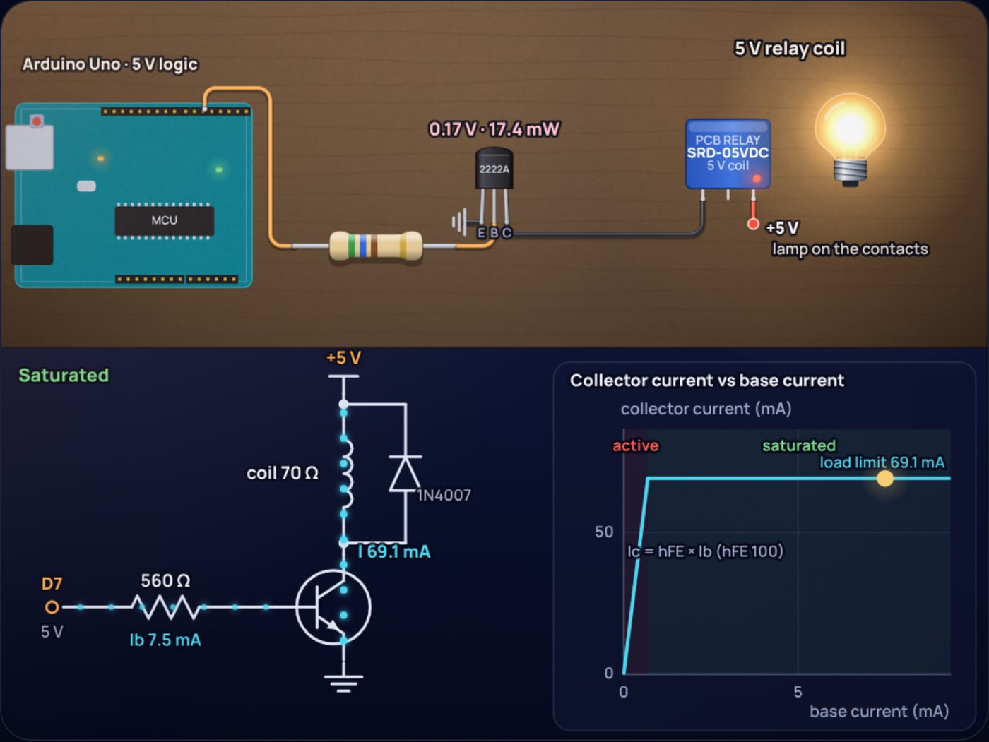
Why can’t an Arduino pin drive a relay or motor directly?
Three reasons, and each one alone is enough.
Current. The ATmega328P datasheet lists 40 mA per I/O pin as an absolute maximum, which is a damage threshold, not a working value. Engineers treat 20 mA as a sensible ceiling. A relay coil wants 71 mA and a small motor 200 mA or more. The ESP32 is in the same position: its strongest drive setting sources up to about 40 mA, and less when several pins are working at once.
Voltage. Many loads need a supply the microcontroller cannot give. A 12 V LED strip or a 12 V relay will not even notice a 5 V pin, and an ESP32 pin only reaches 3.3 V.
Kickback. Coils and motors are inductors. When current through an inductor is cut, the inductor raises whatever voltage it takes to keep that current flowing for a moment. Without a path for it, that spike can reach hundreds of volts, as the relay flyback diode post works out. A microcontroller pin will not survive that.
A transistor solves all three. The pin supplies a few milliamps to the base, and the transistor connects the load to ground through its collector, using the load's own supply.
How do you wire a transistor to switch a relay?
The standard circuit is called a low-side switch, because the transistor sits on the low (ground) side of the load:
- Relay coil from +5 V to the collector of a PN2222A.
- Emitter to ground. That ground must also be connected to the Arduino's GND.
- Arduino pin to the base through the base resistor.
- A 1N4007 diode across the coil, with its striped end (cathode) to +5 V.
The only number to work out is the base resistor. You want the transistor fully on, a state called saturation, where only a few tenths of a volt sit across it. The reliable way is to give the base about one tenth of the collector current. That ratio, collector current over base current, is called the forced beta, and the base resistor calculation post explains why 10 is the usual choice.
Coil current with the transistor saturated: .
Base current at forced beta 10: .
Voltage across the base resistor: .
Base resistor: . Round down to the standard 560 Ω, which gives 7.5 mA.
Heat in the transistor: , under 3 percent of the PN2222A's 625 mW rating.
Round the resistor down, not up. A smaller resistor gives a little more base current, which keeps the transistor saturated. A larger one can leave it half on.
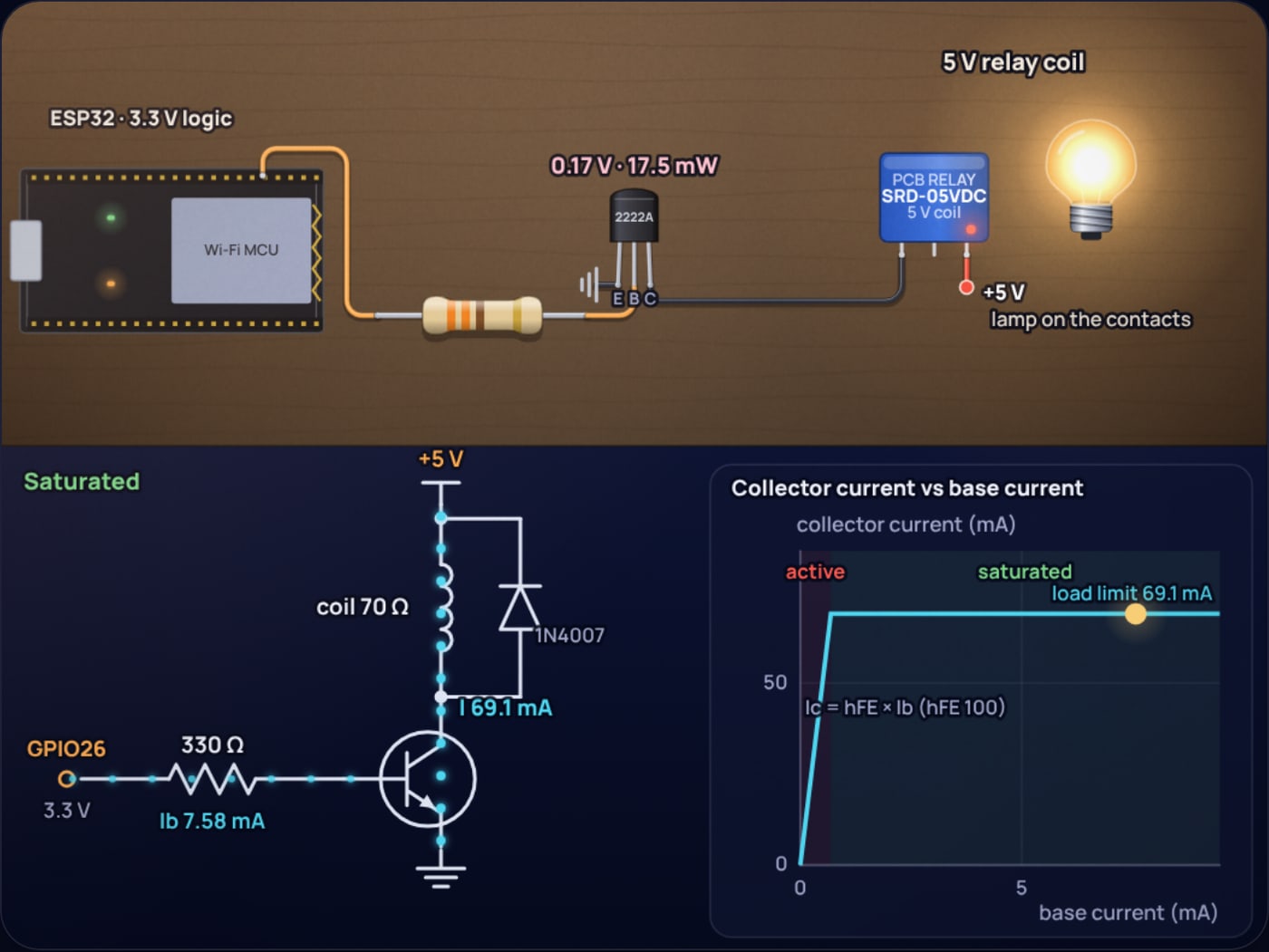
What changes on an ESP32 or other 3.3 V board?
Keep the relay on 5 V and drive only the base from the 3.3 V pin. The transistor does the level shifting for you. The only change is the base resistor, because only 3.3 − 0.8 = 2.5 V is left across it.
How do you drive a DC motor with a transistor?
Same circuit, bigger numbers. A small 5 V hobby motor might draw about 250 mA while running. Through a saturated PN2222A, modelled with its datasheet saturation voltage, it gets about 228 mA.
At a forced beta of 10 the base would need 22.8 mA, more than you want to pull from one Arduino pin. The PN2222A datasheet guarantees a gain of at least 100 at 150 mA, so a forced beta of 20 still leaves a five times margin. That halves the pin current:
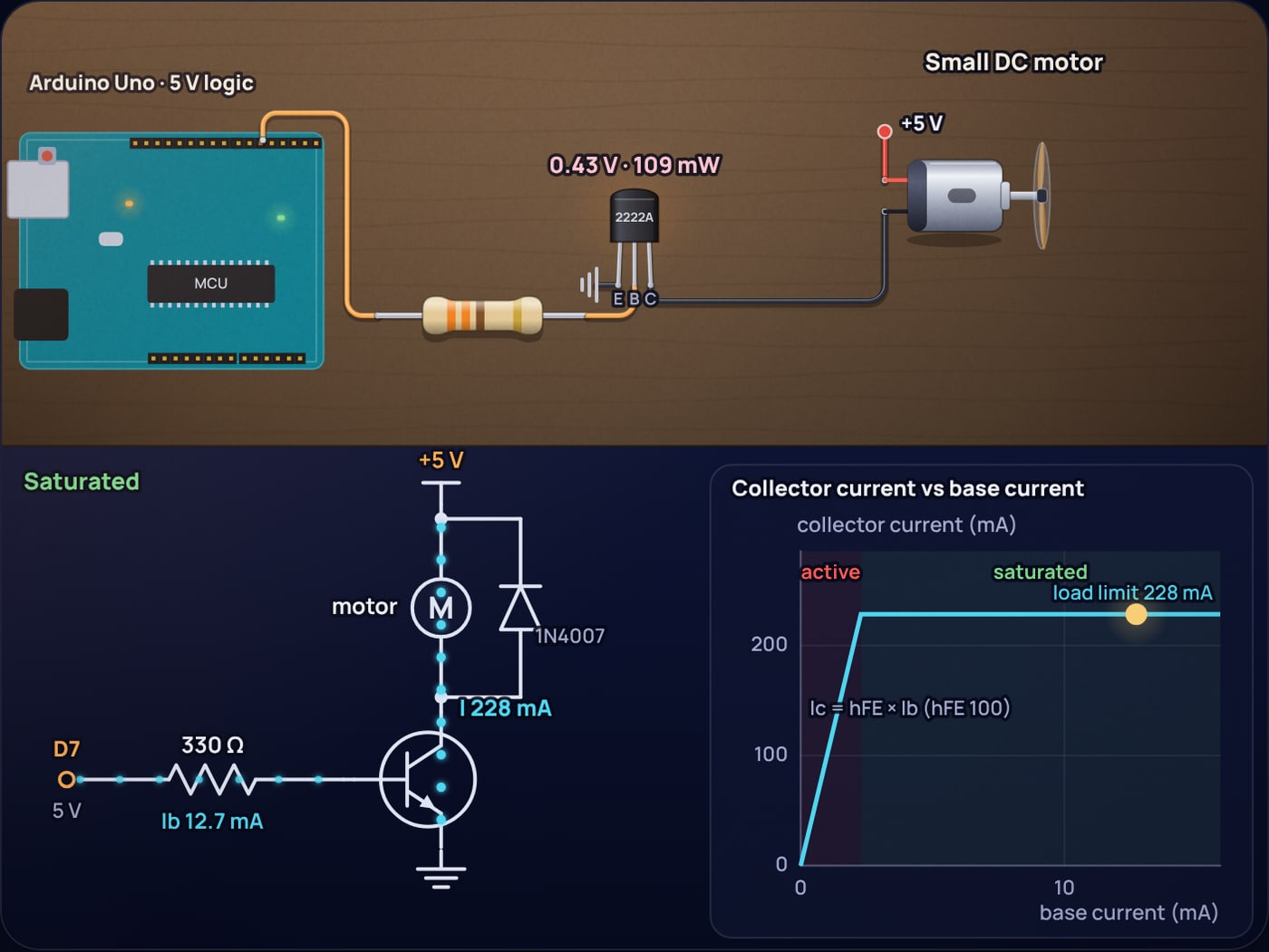
Two cautions. A motor draws several times its running current at the moment it starts or when it stalls, so check that the transistor's 1 A rating covers the stall current of your motor. And this circuit only turns the motor on and off in one direction. To reverse it you need four switches, an H-bridge, which the H-bridge post covers. PWM on the base pin works for speed control with this circuit, provided the flyback diode is in place.
Why does my transistor get hot?
Nine times out of ten the base resistor is too large. Many tutorials compute the base current as load current divided by hFE, using a typical gain of 200 or so from the datasheet curves. That number describes a transistor in its active region, the region used for amplifying, where the collector current is set by the base current. It is the minimum base current, and only for a part with that particular gain.
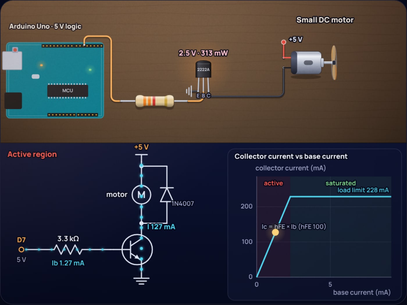
The chart in the simulator makes this visible. The sloped line is the most current the transistor can pass for a given base current. The flat line is the most the load will draw. Saturation means the operating point sits on the flat part, comfortably to the right of the corner. Gains vary by a factor of three between parts of the same type and change with temperature, which is why the corner is never where you think it is, and why a forced beta of 10 to 20 is the habit worth keeping.
Which transistor should you use?
| Part | Type | Max current | Good for | Watch out for |
|---|---|---|---|---|
| BC547B | NPN, TO-92 | 100 mA | LEDs, small relays, signals | Overcurrent with motors; pinout is C B E |
| PN2222A | NPN, TO-92 | 1.0 A | Relays, small motors, buzzers | Base current above 300 mA loads; pinout is E B C |
| IRLZ44N | Logic-level N-MOSFET, TO-220 | 47 A (with heatsink) | LED strips, bigger motors, solenoids | RDS(on) only specified from 4 V gate drive |
Note the pinouts. The BC547 and the PN2222A look identical but their collector and emitter are swapped. If a circuit refuses to switch, check this first.
When is a MOSFET the better choice?
Once the load reaches a few hundred milliamps. A 12 V LED strip drawing half an amp shows why.
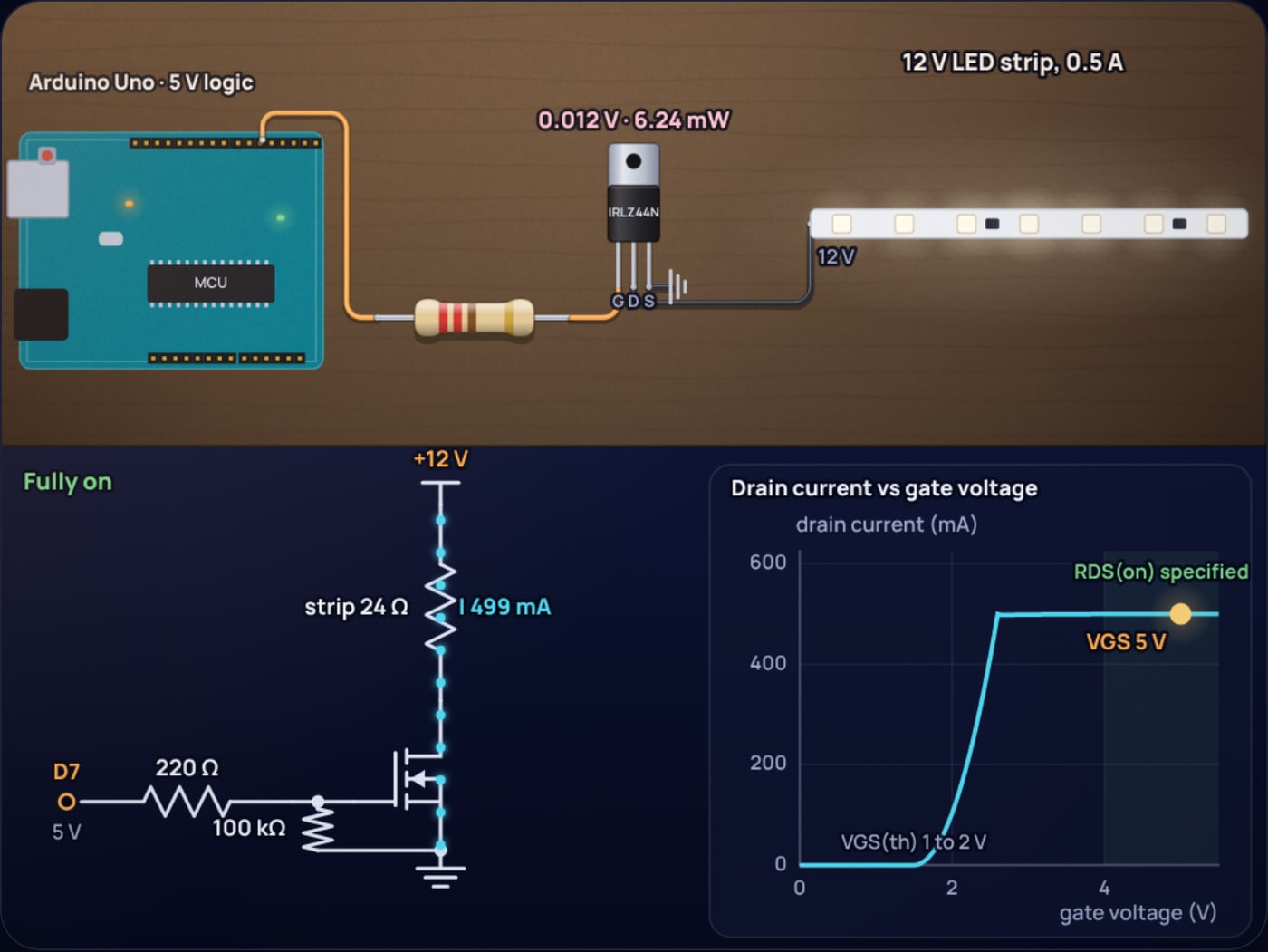
Wire it like the NPN: load from +12 V to the drain, source to ground, pin to the gate through about 220 Ω, and 100 kΩ from gate to ground so the strip stays off while the board boots. The MOSFET gate resistor post explains both values. On a 3.3 V board the IRLZ44N usually works for small loads, but its datasheet does not promise any on-resistance below 4 V of gate drive. Choose a MOSFET whose datasheet lists RDS(on) at 2.5 V if you want a guarantee.
The mistake that looks right: an NPN on the high side
It feels natural to put the switch between the supply and the load, so the load's ground stays connected. With an NPN transistor that does not work. In that position the emitter can only rise to the base voltage minus about 0.7 V, so from a 5 V pin the load sees at most about 4.3 V, and from a 3.3 V pin about 2.6 V, however high the supply. A 12 V relay wired that way never clicks, and the transistor sits in its active region getting hot. NPN transistors and N-channel MOSFETs belong on the low side. Switching the high side needs a PNP or P-channel part plus a small NPN to drive it.
A checklist before you power up
- Load on the collector side, emitter or source to ground.
- Microcontroller ground joined to the load supply's ground.
- Base resistor from (pin voltage − 0.8 V) ÷ (load current ÷ 10), rounded down.
- Base current under about 20 mA; if not, use a MOSFET.
- Diode across every relay coil and motor, cathode to the positive side.
- Transistor current rating above the load's start-up or stall current.
Then open the simulator on the active-region example and slide the forced beta from 200 down to 20. Watching the operating point snap onto the flat line, and the heat readout fall from 313 mW to about 109 mW, is the clearest way to remember why the base resistor matters.
Sources
- onsemi PN2222A datasheet: 1.0 A collector rating, 625 mW, hFE minimum 100 at 150 mA, VCE(sat) 0.3 V at 150 mA and 1.0 V at 500 mA.
- onsemi BC546 to BC548 datasheet: 100 mA collector rating, hFE 200 to 450 for the B grade, VCE(sat) 0.09 V and 0.2 V typical.
- Infineon IRLZ44NPbF datasheet: RDS(on) 25 mΩ at 5 V and 35 mΩ at 4 V, VGS(th) 1 to 2 V.
- LCSC listing for the SRD-05VDC-SL-C relay: 70 Ω coil, 360 mW.
- Microchip ATmega328P absolute maximum ratings: 40 mA per I/O pin.
- ESP32 electrical specifications summary (Deneyap): IOH 40 mA at maximum drive strength.
Frequently asked questions
Can I connect a relay directly to an Arduino pin?
No. A typical 5 V PCB relay has a 70 ohm coil that draws about 71 mA, above the 40 mA absolute maximum of an ATmega328P pin, and the coil throws a voltage spike when it switches off. Drive it through an NPN transistor such as a PN2222A with a base resistor of about 560 ohms and a 1N4007 diode across the coil, or buy a relay module that already includes them.
What base resistor should I use to drive a relay with a transistor?
Divide the coil current by 10 to get the base current, then divide the pin voltage minus about 0.8 V by that current. For a 5 V, 70 ohm relay on an Arduino Uno that is 69 mA divided by 10, about 6.9 mA, and 4.2 V divided by 6.9 mA is about 610 ohms, so use 560 ohms. On a 3.3 V ESP32 use 330 ohms.
Why does my transistor get hot when switching a motor?
Usually because the base resistor is too large, so the transistor is not saturated. It then passes only hFE times the base current and drops volts across itself. In our example a 3.3 kilohm base resistor leaves a PN2222A dropping 2.5 V and dissipating 313 mW while the motor gets 127 mA instead of 228 mA. Lower the base resistor or use a MOSFET.
Do I need a diode across a DC motor?
Yes, for a motor switched by a single transistor. A motor winding is an inductor, and when the transistor turns off the current tries to keep flowing, which can push the collector voltage far above the transistor’s 40 V rating. A 1N4007 or a Schottky diode across the motor, cathode to the positive supply, gives that current a safe path.
Is a MOSFET better than a transistor for Arduino projects?
For loads above a few hundred milliamps, yes. A logic-level MOSFET such as the IRLZ44N draws no steady gate current and switches a 0.5 A LED strip with about 12 mV across it, where a PN2222A would need 51 mA of base current and drop about 0.8 V. For small loads like a relay or an LED, a PN2222A or BC547 is simpler and cheaper.
 555 Timer Frequency Formula: Where 1.44 Comes From
 ADC Resolution vs Accuracy: ENOB, INL and the Reference
