What Wire Size for 12V Solar Over 10 Metres?
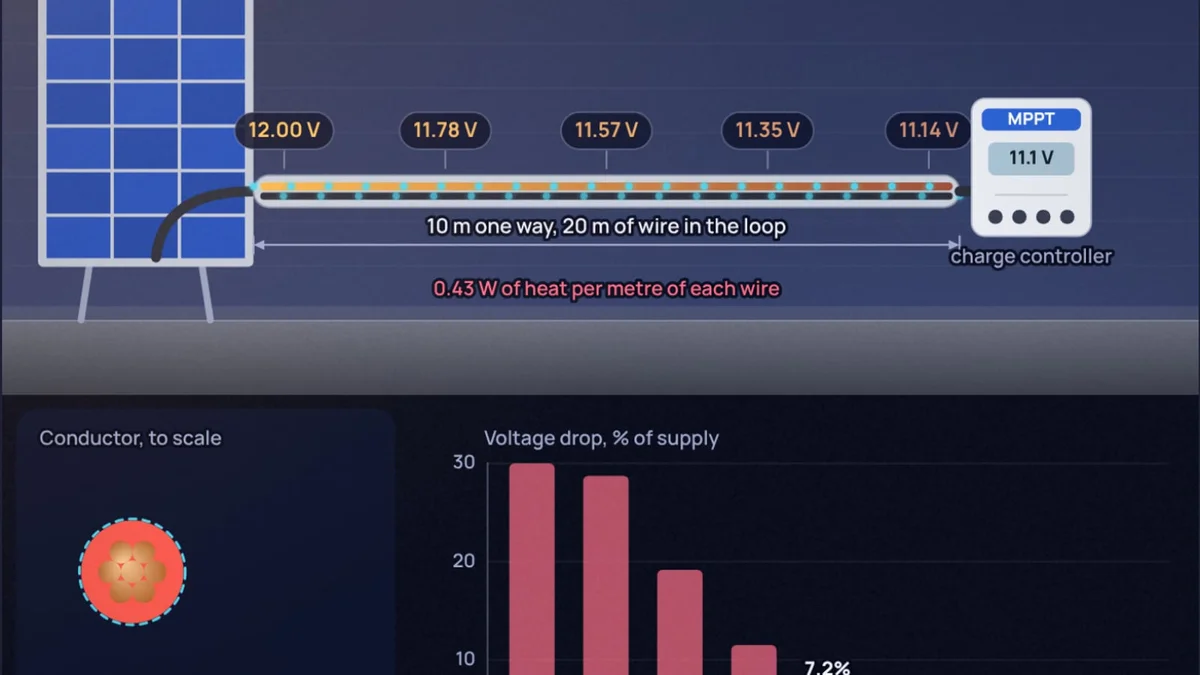
Two 100 W panels on a shed roof, a charge controller and a battery in the house, 10 metres apart. Run them in parallel on the 4 mm² red and black solar cable that every shop sells and about 0.85 V vanishes on the way. That is 7 percent of a 12 V system and about 8 W of a 200 W array warming the cable instead of the battery. Nothing gets hot, nothing trips, the system just quietly underperforms for years.
This post answers the question people actually type: what size wire do I need for 12 V solar over 10 metres? You can follow along in the voltage drop calculator, which draws the cable with its voltage fading along the run and picks the thinnest size that meets your limit. If you are wiring 12 V loads such as LED strips or a fridge rather than panels, the earlier post on what gauge wire for 12 V covers those in AWG.
How much current does a 12 V solar array push through the cable?
Start from the panel datasheet, not the wattage. A typical "12 V" 100 W panel, such as the Renogy RSP100D-BK, lists a maximum power voltage of 20.4 V and a maximum power current of 4.91 A, with an open-circuit voltage of 24.3 V and a short-circuit current of 5.21 A. The panel is called 12 V because it is meant to charge a 12 V battery; it works at about 18 to 20 V.
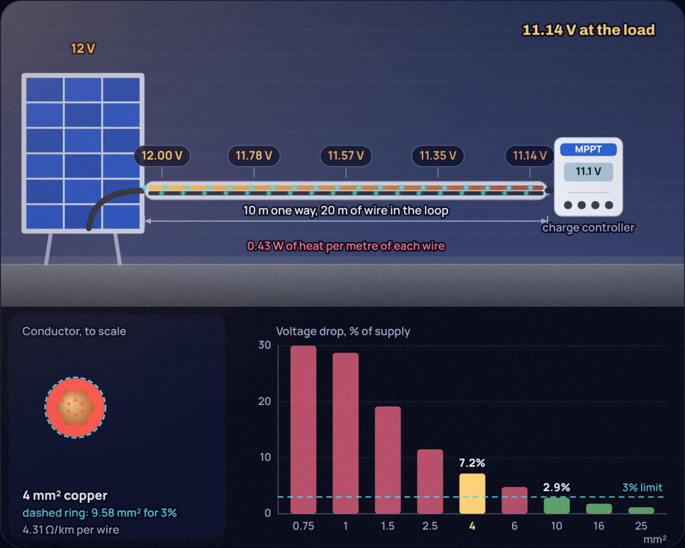
Two of those in parallel deliver 9.82 A at 20.4 V. Two in series deliver 4.91 A at 40.8 V. Same 200 W, very different cable. In the simulator I use a round 10 A for the parallel case, which gives the figures in the screenshots.
What is the formula for voltage drop in solar cable?
Each conductor has a resistance set by its material, length and cross-section. The current flows out on the positive cable and back on the negative, so a 10 m run has 20 m of copper in the loop:
Here is the one-way length in metres, the area in mm² and the resistivity. For annealed copper at 20 °C, , the International Annealed Copper Standard defined in ASTM B193. Rearranged, the smallest area for a given drop limit is
Loop resistance:
Drop:
As a share of 12 V nominal: . As a share of the 20.4 V working voltage: 4.2 percent
Heat in the cable: , about 4 percent of the array
Area for 3 percent of 12 V:
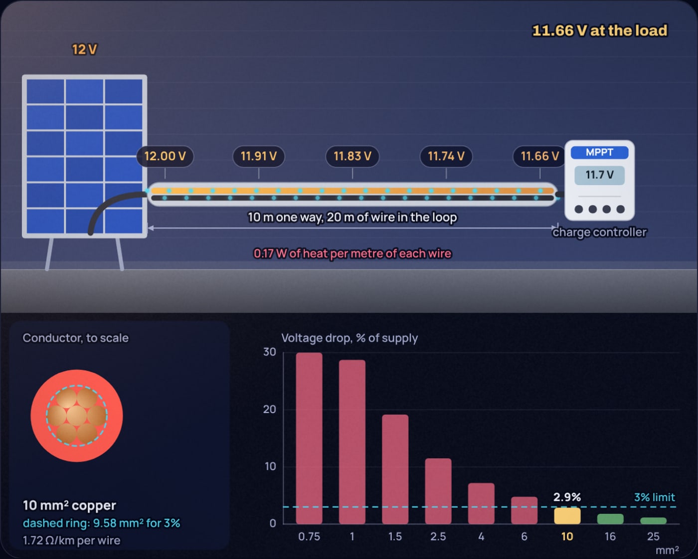
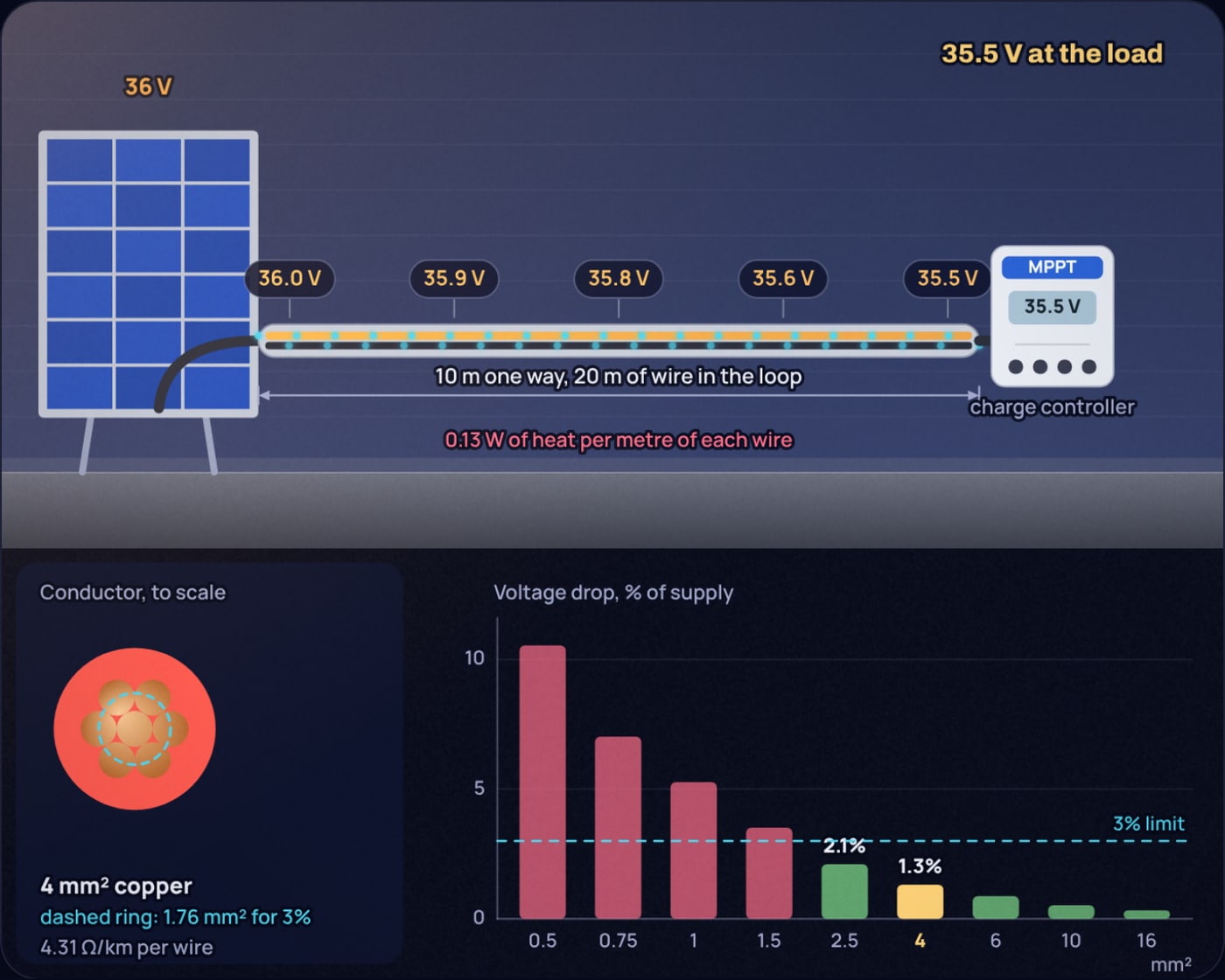
That last line is why 10 mm² comes out of the calculator: 6 mm² is too small and 10 mm² is the next standard size. On 10 mm² the 9.82 A run drops 0.34 V, 2.8 percent of 12 V; at a round 10 A it is 2.9 percent, which is Figure 2.
Should you measure the drop against 12 V or against the panel voltage?
This is where most 12 V solar advice gets muddled, and it depends on your charge controller.
With an MPPT controller, the panel works at its maximum power voltage and the controller converts down to the battery voltage. Volts lost in the panel cable are simply power lost: 0.85 V out of 20.4 V is 4.2 percent of the energy. Measuring against 20.4 V is the honest number, and by that yardstick 6 mm² (2.8 percent) is enough.
With a PWM controller, the panel is connected almost directly to the battery, so it works at the battery voltage, around 13 to 14.5 V. The panel has some voltage to spare, and a small cable drop eats into that spare rather than into the charge current. But the spare shrinks on hot days, because panel voltage falls with temperature, and at that point every volt in the cable costs current. Sizing against 12 V nominal, as the simulator does, is the conservative choice for PWM systems.
Either way, the cable from the controller to the battery matters most. The controller regulates the voltage at its own terminals. If that cable drops 0.25 V, the battery is charged to 0.25 V less than you set, which on a lead-acid battery is the difference between a full charge and slow sulphation.
| Cable | Current | Run (one way) | Drop | Share | Heat |
|---|---|---|---|---|---|
| 2.5 mm², panels in parallel | 9.82 A | 10 m | 1.35 V | 11.3% of 12 V, 6.6% of 20.4 V | 13.3 W |
| 4 mm², panels in parallel | 9.82 A | 10 m | 0.85 V | 7.1% of 12 V, 4.2% of 20.4 V | 8.3 W |
| 6 mm², panels in parallel | 9.82 A | 10 m | 0.56 V | 4.7% of 12 V, 2.8% of 20.4 V | 5.5 W |
| 10 mm², panels in parallel | 9.82 A | 10 m | 0.34 V | 2.8% of 12 V, 1.7% of 20.4 V | 3.3 W |
| 4 mm², panels in series | 4.91 A | 10 m | 0.42 V | 1.0% of 40.8 V | 2.1 W |
| 4 mm², controller to battery | 14.8 A | 2 m | 0.26 V | 1.9% of 13.5 V | 3.8 W |
| 6 mm², controller to battery | 14.8 A | 2 m | 0.17 V | 1.3% of 13.5 V | 2.5 W |
The controller-to-battery current assumes 200 W of charge at 13.5 V, about 14.8 A. All figures are for copper at 20 °C.
Why does wiring panels in series fix the problem?
Because the drop in volts depends only on current, and the power lost goes with current squared. Put the two panels in series and the current halves to 4.91 A while the voltage doubles to 40.8 V.
Drop:
Share of 40.8 V:
Heat: , a quarter of the parallel case
Area for 3 percent:
The required area falls by a factor of four: half from the lower current, half from the higher voltage it is measured against. It is the same reason power lines use high voltage. The catch is that you need an MPPT controller rated for the series open-circuit voltage (here 2 × 24.3 = 48.6 V, more on a cold morning), and partial shade on one panel now drags down both.
Is real solar cable worse than the textbook copper?
A little. Solar cable is usually flexible, tinned copper (class 5 in IEC 60228), and the standard allows it more resistance than ideal solid copper. The maximum for 4 mm² tinned class 5 conductor is 5.09 Ω per kilometre at 20 °C, against 4.31 Ω/km from the ideal resistivity. That is 18 percent more. Rerun worked example 1 with 5.09 Ω/km and the drop is 1.00 V, not 0.85 V.
Temperature adds more. Copper's resistance rises about 0.39 percent per degree, and a cable lying on a sunny roof can easily reach 60 to 70 °C. At 70 °C the 4 mm² example in the simulator goes from 7.2 to 8.6 percent. Both effects argue for going one size up when you are close to the limit.
What about the cable from the battery to the loads?
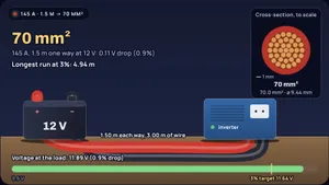
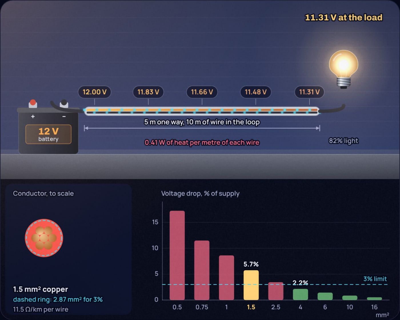
The same rules apply, with bigger currents. A 1200 W inverter on 12 V draws about 100 A, so even 2 m of 25 mm² cable drops 0.28 V and dissipates 28 W. A 72 W LED strip at 6 A on 5 m of 1.5 mm² wire drops 0.69 V, 5.8 percent, and the far end runs visibly dimmer. Figure 4 shows that one; 4 mm² is what brings it under 3 percent. For LiPo and other high-current battery packs, the battery's own internal resistance adds to the cable drop, which the LiPo C rating post works through.
So what size should you buy?
For the common Indian rooftop or shed setup with two 100 W panels 10 m from the controller:
- Panels in parallel, PWM controller: 10 mm² copper, or accept about 5 percent loss on 6 mm².
- Panels in parallel, MPPT controller: 6 mm² solar cable (2.8 percent of the working voltage).
- Panels in series, MPPT controller: 4 mm² solar cable is plenty (about 1 percent).
- Controller to battery: 6 mm² for runs up to 2 m at 15 A, and keep it as short as the layout allows.
Before you buy, put your own numbers in the voltage drop calculator: set your panel current and the one-way distance, switch between 3 and 5 percent, and drag the wire size until the bar turns green. The solar panel angle guide covers the other easy win on the same installation.
Sources
- Renogy RSP100D-BK 100 W panel datasheet (Vmp 20.4 V, Imp 4.91 A, Voc 24.3 V)
- IEC 60228 conductor resistance table, including tinned class 5 values (myCableEngineering)
- Resistivity of annealed copper, 1/58 Ω·mm²/m at 20 °C: ASTM B193 and NBS Handbook 100, Copper Wire Tables
- Voltage drop limits of 3 percent for lighting and 5 percent for other uses: IEC 60364-5-52, Annex G, Table G.52.1
Frequently asked questions
What size wire do I need for a 12V solar panel 10 metres away?
For about 10 A from two 100 W panels in parallel, 10 mm² copper keeps the drop under 3 percent of 12 V (2.8 percent). If you count against the panel’s working voltage of about 20 V, as you can with an MPPT controller, 6 mm² is enough. 4 mm², the common solar cable size, loses about 7 percent of 12 V over that distance.
Is 4mm² cable enough for solar panels?
For one 100 W panel (about 4.9 A) over 10 m it is fine: the drop is about 0.42 V. For two panels in parallel (about 9.8 A) it loses about 0.85 V and 8.3 W, which is too much at 12 V. Wire the two panels in series into an MPPT controller and 4 mm² loses only about 1 percent.
Should solar panels be wired in series or parallel to reduce voltage drop?
Series, if your charge controller is an MPPT type that accepts the higher voltage. Series doubles the voltage and halves the current, so the same cable loses half the volts and a quarter of the power. PWM controllers need panels matched to the battery voltage, which usually means parallel.
Does voltage drop matter between the charge controller and the battery?
Yes, more than anywhere else per metre. The controller regulates the voltage at its own terminals, so any drop in the battery cable means the battery is charged to a lower voltage than set. Keep that run short, 1 to 2 m, and size it for under 2 percent.
Do I use one-way or round-trip length for solar cable?
Round trip. The current goes out on the positive cable and back on the negative one, so a panel 10 m from the controller has 20 m of conductor in the circuit. Most online calculators ask for the one-way length and double it internally.
 How Many Solar Panels Do I Need for My House?
 What Size Cable for a 2000 W Inverter at 12 V?