How do you calculate voltage drop in a cable?
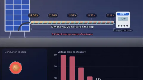
Multiply the current by the resistance of both wires: drop = I × 2L × ρ ÷ A, where L is the one-way length, A the conductor area and ρ the resistivity (0.0172 Ω·mm²/m for copper). A 10 A load at the end of 10 m of 4 mm² copper loses 0.86 V. On a 230 V circuit that is 0.4%, nothing to worry about. On a 12 V solar system it is 7.2%, and the charge controller sees only 11.14 V.
That is the whole problem in one example: the volts lost depend only on current, length and wire size, but whether they matter depends on the supply voltage. Most limits are 3 percent for lighting and sensitive loads and 5 percent for everything else. The simulation draws the cable with its voltage marked along the run, shows the heat it wastes and picks the thinnest standard size that meets your limit, in mm² as used in India and Europe or in AWG. For a worked 12 V solar example, read what wire size you need for 12 V solar over 10 metres.
Key results from the simulation
- Low voltage needs thick wire: 10 A over 10 m needs 9.58 mm² of copper for a 3 percent drop at 12 V, so a 10 mm² cable. At 24 V the same 10 A needs half that, 4.79 mm², so 6 mm².
- Length doubles: the current goes out and comes back, so a 10 m run has 20 m of wire in the loop. Forgetting this halves the calculated drop.
- Aluminium needs about 1.6 times the area: its resistivity is 1.64 times copper's. A 40 m, 32 A feed at 230 V drops 3.1% on 10 mm² aluminium and 1.9% on 10 mm² copper.
- Hot wire loses more: copper's resistance rises about 0.39 percent per degree. The 12 V solar example drops 7.2% at 20 °C and 8.6% with the conductor at 70 °C.
Six setups worth trying
Each button loads the setup into the simulation. Lengths are one way, from the supply to the load. Numbers are for conductors at 20 °C unless stated.
12 V solar panel, 10 m from the charge controller
DC, 10 A, 4 mm² copperTwo 100 W panels in parallel deliver about 10 A at 12 V nominal. Run that through 10 m of 4 mm² cable and the loop resistance is 86.2 mΩ, so 0.86 V disappears and 8.6 W warms the cable. That is a 7.2% drop, more than twice the 3 percent target.
The calculator's answer is 10 mm², which drops 0.34 V (2.9%). The cheaper fix is to raise the voltage: wire the panels in series into an MPPT controller and the current halves, so the drop in volts halves and the supply doubles. The 12 V solar wire size post works through both options.
A 12 V LED strip 5 m from its power supply
DC, 6 A, 1.5 mm² copperA 72 W strip draws 6 A. On 1.5 mm² wire over 5 m the drop is 0.69 V (5.7%), and the far end of the strip runs visibly dimmer and often yellower. LED strips are worse than lamps here, because their current limiting resistors leave little headroom.
The limit-meeting size is 4 mm². The other fix is feeding the strip from both ends, which halves the current in each lead. The existing post on what gauge wire for 12 V covers strips and fridges in AWG.
A 3 kW geyser on 2.5 mm² wire, 25 m from the board
Single-phase AC, 13 AA 3 kW water heater on 230 V draws 13 A. Through 25 m of 2.5 mm² copper the drop is 4.5 V, which is 1.9%, inside the 3 percent limit. The heater still sees 225.5 V. Yet the cable turns 58.3 W into heat, spread over 50 m of conductor.
At mains voltage, drop rarely decides the size for normal house runs. Current carrying capacity does: 2.5 mm² PVC cable is good for roughly 27 A clipped to a wall, and less when bunched in conduit or buried in insulation. Long runs to an outhouse or a borewell pump are where drop starts to matter.
Aluminium versus copper on a 40 m feed
Single-phase AC, 32 A, 10 mm²Aluminium is cheaper and lighter, and it is common for service cables and long feeders in India. Its resistivity is 1.64 times copper's, so the same 10 mm² cable over 40 m at 32 A drops 7.2 V (3.1%) instead of 4.4 V (1.9%) for copper, and wastes 232 W instead of 141 W.
The rule of thumb is to go one standard size up when you switch to aluminium. Both pass the 5 percent limit here, but only copper passes 3 percent. Aluminium also needs terminals rated for it, because it creeps under pressure and its oxide layer insulates.
A 15 A circuit on 14 AWG, 30 m (about 100 ft) away
Single-phase AC, 120 V14 AWG copper is 1.63 mm across, 2.08 mm², and has 8.29 Ω per kilometre at 20 °C. A full 15 A load 30 m away drops 7.5 V, which is 6.2% of 120 V. The load sees 112.5 V.
US guidance (an informational note in the National Electrical Code) suggests 3 percent for a branch circuit. That needs 10 AWG for this run. Lower supply voltage is why long US runs are upsized more often than the same runs at 230 V.
A 1200 W inverter on a 12 V battery, 2 m of cable
DC, 100 A, 25 mm² copperAt 12 V a 1200 W inverter pulls about 100 A. Even 2 m of 25 mm² cable, a thick welding-style lead, drops 0.28 V (2.3%) and wastes 27.6 W. Each metre of each wire dissipates 6.9 W.
Short and fat is the rule for battery leads. Inverters cut out at low input voltage, and a sagging battery plus cable drop trips that alarm long before the battery is flat. This is also why bigger systems move to 24 V or 48 V.
Copper cable: drop for 10 A over 10 m, and the longest run for 3 percent
| Size | Ω/km per wire | Drop at 10 A, 10 m | Drop at 12 V | Heat | Max run, 12 V | Max run, 230 V |
|---|---|---|---|---|---|---|
| 1.5 mm² | 11.49 | 2.30 V | 19.2% | 23.0 W | 1.57 m | 30 m |
| 2.5 mm² | 6.90 | 1.38 V | 11.5% | 13.8 W | 2.61 m | 50 m |
| 4 mm² | 4.31 | 0.86 V | 7.2% | 8.6 W | 4.18 m | 80 m |
| 6 mm² | 2.87 | 0.57 V | 4.8% | 5.7 W | 6.26 m | 120 m |
| 10 mm² | 1.72 | 0.34 V | 2.9% | 3.4 W | 10.4 m | 200 m |
| 16 mm² | 1.08 | 0.22 V | 1.8% | 2.2 W | 16.7 m | 320 m |
| 25 mm² | 0.69 | 0.14 V | 1.1% | 1.4 W | 26.1 m | 500 m |
Resistance from the annealed copper standard, 1/58 Ω·mm²/m at 20 °C. IEC 60228 allows real stranded conductors up to about 7 percent more (for example 7.41 Ω/km maximum for 2.5 mm² against 6.90 here), so add a margin when you are close to the limit. Max run is one way, for 10 A and a 3 percent drop.
How the calculator works
Each conductor has resistance R = ρL ÷ A. For copper the simulation uses ρ = 1/58 = 0.017241 Ω·mm²/m at 20 °C, the International Annealed Copper Standard. For aluminium it uses 0.028264 Ω·mm²/m (61 percent of copper's conductivity), the value in Indian Standard IS 10810 Part 2. The "hot wire" setting raises both with temperature coefficients of 0.00393 and 0.00403 per °C.
AWG sizes are converted to area with the standard formula d = 0.127 mm × 92^((36 − n) ÷ 39), so 12 AWG is 2.05 mm across and 3.31 mm². At 75 °C that gives 1.93 Ω per 1000 ft, close to the 1.98 Ω/kft the US electrical code lists for stranded 12 AWG.
The circuit has two conductors in series with the load, so the loop resistance is 2LR' and the drop is I times that. The percent drop is the drop divided by the supply voltage. The heat is I² times the loop resistance. The size for the limit is the area A = 2LIρ ÷ (limit × V), rounded up to the next standard mm² or AWG size.
The 3 percent and 5 percent limits are the IEC 60364-5-52 Annex G values for installations fed from a public low voltage network (3 percent for lighting, 5 percent for other uses), the same figures the US code's informational notes recommend. The red verdict also checks a rough current rating so a cable that is merely within the drop limit but too thin to carry the current is flagged.
What the model leaves out
- Reactance and power factor: for AC the model treats the cable as a pure resistance at unity power factor. Above about 16 mm², or with motors, the cable reactance (about 0.08 mΩ per metre) and a power factor below 1 add a little more drop.
- Three-phase: a balanced three-phase circuit drops √3 × I × L × R' instead of 2 × I × L × R'. The simulation is single-phase and DC only.
- Real conductor resistance: stranded cable is allowed to be a few percent above the ideal value. See the table note.
- Inrush and motor starting: motors draw several times their running current when they start, so the drop at that moment is much larger.
- Connections: every crimp, fuse holder, switch and terminal adds resistance. On 12 V systems a single poor joint can add as much drop as metres of cable.
- Current capacity: the ampacity check is a rough guide for PVC cable on a wall. Bunching, conduit, insulation and hot roofs reduce what a cable can carry. Use your wiring code and the cable maker's tables for that.
Common misconceptions
"Voltage drop depends on the voltage." The drop in volts does not: 10 A through 0.086 Ω loses 0.86 V whether the supply is 12 V or 230 V. Only the percentage changes, which is why low-voltage systems need much thicker wire.
"If the wire does not get hot, it is big enough." Ampacity and voltage drop are different limits. A 12 V run can be cool to the touch and still deliver 10 percent less voltage than the load needs.
"Use the one-way length." The current goes there and back. Unless the return is a vehicle chassis, use twice the distance.
Frequently asked questions
What is the formula for voltage drop?
For DC or single-phase AC: voltage drop = 2 × length × current × resistivity ÷ area. With length in metres, area in mm² and copper resistivity 0.0172 Ω·mm²/m, 10 A over 10 m of 4 mm² copper drops 0.86 V.
What is an acceptable voltage drop?
IEC 60364-5-52 gives 3 percent for lighting and 5 percent for other uses on installations fed from the public network. Low-voltage DC systems usually aim for 3 percent or less, because the loads and chargers have little headroom.
What size wire do I need for 12V over 10 metres?
For 10 A and a 3 percent limit you need at least 9.58 mm² of copper, so 10 mm² (about 7 AWG). For a 5 percent limit, 6 mm² is enough. Halving the current, or doubling the voltage, halves the area you need.
Does aluminium wire have more voltage drop than copper?
Yes. Aluminium's resistivity is about 1.64 times copper's, so for the same drop it needs about 1.6 times the cross-section, usually one standard size larger.
Is voltage drop calculated on one way or round trip length?
Round trip. Current flows to the load on one conductor and back on the other, so the resistance of both counts. Formulas that use the one-way length include a factor of 2 for this.
Keep learning
What Wire Size for 12V Solar Over 10 Metres?
Two 100 W panels 10 m from the controller: 4 mm² cable loses 7 to 8% at 12 V. The maths, the sizes that work and why wiring panels in series is cheaper.
What Gauge Wire for 12V? Size for Voltage Drop
At 12 V, voltage drop, not ampacity, picks the wire. How to size 12 V wire from round-trip length and a 3% limit, with LED strip and fridge examples.

Why Is Electricity Transmitted at High Voltage? The Math
Why is electricity transmitted at high voltage? We work the I²R loss for a real 345 kV line, show why 1,100 kV is about the ceiling, and when HVDC wins.
PCB Trace Width for Current: IPC-2221 vs IPC-2152
IPC-2221 says internal traces need 2.6x the width. IPC-2152 test data says they run cooler. How to size a trace for 2 A, its voltage drop, and vias.