How do you set the gain of an op amp?
With two resistors. An inverting amplifier has gain −Rf / Rin, a non-inverting amplifier 1 + Rf / Rg, and a difference amplifier with matched pairs Rf / Rin times the difference of its inputs. Rin = 10 kΩ and Rf = 100 kΩ give −10 inverting, or 11 non-inverting.
Gain is only the start. The op amp's gain bandwidth product sets how fast the stage can go, and the supply sets how big the output can get. The calculator checks both. For the gain formulas with worked examples read inverting vs non-inverting amplifier, and for the bandwidth side gain bandwidth product explained.
Datasheet figures the calculator uses
- LM358: 0.7 MHz, 0.3 V/µs. TI's sheet puts the output 2 V typical below the positive rail at 30 V and 5 mV above the negative rail, so it suits single supplies but not big swings near the top.
- TL072: 5.25 MHz, 20 V/µs. ±13.5 V typical output on ±15 V into 10 kΩ. TI lists 3 MHz for the NS and PS packages and the M grade.
- NE5532: 10 MHz, 9 V/µs in onsemi's datasheet, with ±13 V typical into 600 Ω. TI's current sheet gives 12 MHz and 5 V/µs instead.
- OPA2134: 8 MHz, 20 V/µs. Output to within 1.2 V of the positive rail and 0.5 V of the negative rail at 10 kΩ.
Seven amplifier designs
Each loads the schematic and the scope with the circuit, part, supply and test signal.
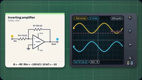
An inverting gain of 10 with a TL072
Gain −10Rin = 10 kΩ and Rf = 100 kΩ give exactly −10. A 500 mV peak sine comes out 5 V peak and upside down, well inside the ±13.5 V the TL072 reaches on ±15 V.
The noise gain is 1 + 100/10 = 11, so the bandwidth is 5.25 MHz ÷ 11 = 477 kHz, not 525 kHz. The largest input before clipping is 1.35 V peak.
An LM358 on 5 V clips at the top
ClippingA non-inverting gain of 11 on a single 5 V supply, biased at 2.5 V. A 200 mV input asks for 2.2 V peak, so the output would need to reach 4.7 V.
The LM358 can only get to about 3.5 V on 5 V (TI gives 1.5 V maximum below the rail there) but almost to 0 V, so the top of the wave is flattened and the bottom is not. The largest clean input is 90.9 mV peak.
Gain of 100 runs out of bandwidth at 20 kHz
6.93 kHzRin = 10 kΩ and Rf = 1 MΩ around an LM358. The noise gain is 101, so the −3 dB point is 0.7 MHz ÷ 101 = 6.93 kHz.
At 20 kHz the single-pole model puts the gain at about 32.7 instead of 100, and the output lags by 71° on top of the inversion. Split the gain across two stages or use a faster part.
A ×100 microphone preamp with an NE5532
101For a non-inverting gain of 100 with Rg = 1 kΩ, the ideal Rf is 99 kΩ. The nearest E24 value is 100 kΩ, which gives 101 because of the "1 +".
At 10 MHz the bandwidth is 99 kHz, comfortably past 20 kHz. A 10 mV peak signal becomes 1.01 V peak, with room for inputs up to 129 mV peak.
An OPA2134 line driver at gain 2
8 V pkTwo equal 10 kΩ resistors give a non-inverting gain of 2. A 4 V peak input becomes 8 V peak, and at 20 kHz that needs 1.01 V/µs of slew rate, a small part of the 20 V/µs available.
The output can reach −14.5 to +13.8 V on ±15 V, so the largest clean input is 6.9 V peak.
A difference amplifier with 1% resistors
4.99Rin = 10 kΩ and Rf = 49.9 kΩ on both sides give 4.99 times (V2 − V1). The noise gain is still 1 + Rf/Rin = 5.99, so the TL072 gives 876 kHz.
The circuit only rejects the common voltage if the two ratios match. That is why the E96 series matters here: it is the tolerance of the pairs, not the exact gain, that sets how well it subtracts.
When the LM358 cannot keep up
Slew limitedAn inverting gain of 10 on ±15 V with a 1 V peak input at 10 kHz. The bandwidth is 63.6 kHz, so small signals would be fine, but a 9.88 V peak sine at 10 kHz needs 2π × 10,000 × 9.88 = 0.621 V/µs.
The LM358 manages 0.3 V/µs, so the output turns into a triangle. At this amplitude it stays clean only up to about 4.83 kHz.
E24 resistors for common gains with a 10 kΩ input resistor
| Gain | Inverting Rf | Non-inverting Rf | LM358 bandwidth |
|---|---|---|---|
| 2 | 20 kΩ (−2) | 10 kΩ (2) | 233 kHz |
| 5 | 51 kΩ (−5.1) | 39 kΩ (4.9) | 115 kHz |
| 10 | 100 kΩ (−10) | 91 kΩ (10.1) | 63.6 kHz |
| 20 | 200 kΩ (−20) | 180 kΩ (19) | 33.3 kHz |
| 50 | 510 kΩ (−51) | 470 kΩ (48) | 13.5 kHz |
| 100 | 1 MΩ (−100) | 1 MΩ (101) | 6.93 kHz |
Bandwidth for the inverting column, from the LM358's 0.7 MHz. The non-inverting column shows the gain each E24 value really gives: for 10, 91 kΩ gives 10.1, while 20 kΩ and 180 kΩ give exactly 10.
How the calculator works
It finds the ideal feedback resistor for your gain and input resistor, rounds it to the nearest E24 or E96 value and works the real gain back out. It also tries every input resistor from 1 kΩ to 100 kΩ in the series and lists the pairs that land closest.
Bandwidth is the gain bandwidth product divided by the noise gain, 1 + Rf/Rin, which is the same for all three circuits with the same resistors. The gain at your frequency follows a single-pole roll-off.
The output limits come from each datasheet's swing figures, applied to your supply. On a single supply the output is assumed to sit at half the supply. The largest clean input is the room to the nearer limit divided by the gain.
The scope trace is the ideal output, cut at the limits and then held to the slew rate. A sine needs 2π f Vpeak of slew rate.
What the model leaves out
- Load and temperature. Swing figures are for 10 kΩ loads (600 Ω for the NE5532) at 25 °C. Heavier loads and other temperatures pull the output further from the rails.
- Input range. The inputs have a common-mode limit too; the LM358's stops 2 V below the positive rail, the TL072's 4 V above the negative one.
- Offset and noise. Input offset voltage is multiplied by the noise gain, and so is the op amp's own noise.
- Source impedance. An inverting stage loads the source with Rin; a non-inverting stage barely loads it at all.
Common misconceptions
"Inverting and non-inverting with the same resistors have the same bandwidth." They do, because they share the noise gain. But the inverting one has a smaller gain, so it looks slower for the gain you get.
"Bandwidth is GBW ÷ gain." It is GBW ÷ noise gain. For a gain of −1 that is half the naive answer.
"A 30 V supply gives a 30 V swing." Most op amps stop 1 to 2 V short of each rail. Only rail-to-rail output parts get close.
Frequently asked questions
What is the gain of an inverting amplifier?
−Rf / Rin. The minus sign means the output is upside down. Rf = 100 kΩ and Rin = 10 kΩ give −10.
What is the gain of a non-inverting amplifier?
1 + Rf / Rg. It can never be below 1. With Rf = 100 kΩ and Rg = 10 kΩ the gain is 11.
How do I choose resistor values for an op amp?
Pick the input resistor first, often 1 kΩ to 100 kΩ, then the feedback resistor from the gain formula, rounded to a standard value. Very small values load the op amp; very large ones add noise and offset from bias current.
Why does my op amp output clip below the supply voltage?
The output stage cannot reach the rails. A TL072 on ±15 V reaches about ±13.5 V into 10 kΩ, and an LM358 stops about 2 V below its positive rail.
What bandwidth will my op amp stage have?
About the gain bandwidth product divided by 1 + Rf/Rin. An LM358 at 0.7 MHz with a gain of −10 gives 63.6 kHz.
Keep learning
Inverting vs Non-Inverting Amplifier: Gain and Examples
Inverting gain is −Rf/Rin, non-inverting is 1 + Rf/Rg. Where both formulas come from, worked examples with standard resistors, clipping and bandwidth.

Op Amp Gain Bandwidth Product Explained (Noise Gain)
Op amp bandwidth is GBW divided by the noise gain, not the signal gain. Worked LM358 and TL072 numbers, gain accuracy, slew rate and computed Bode plots.
How Does a Transistor Amplify? It's a Valve, Not a Source
A transistor doesn't make energy: a millivolt on the base steers current from the supply. Transconductance, gain = gm × RC, and a worked common-emitter design.

RC Low Pass Filter Cutoff Frequency: What −3 dB Means
fc = 1/(2πRC) is where the output is 0.707 of the input, half power and −45°. Why the slope there is only 10 dB/decade, and how loading moves it.