Inverting vs Non-Inverting Amplifier: Gain and Examples
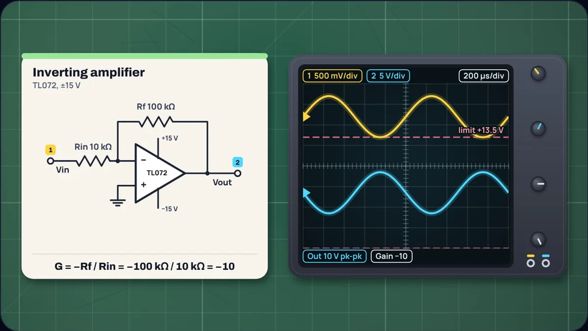
Take a TL072, a 10 kΩ resistor and a 100 kΩ resistor. Wire them one way and a 0.5 V sine comes out 5 V tall and upside down: a gain of −10. Move the input to the other pin, send the 10 kΩ to ground instead, and the same sine comes out 5.5 V tall and the right way up: a gain of 11. Same chip, same two resistors, and the two answers differ by more than a sign.
This guide derives both formulas from the one rule that governs an op amp with feedback, works through examples with standard resistor values and the figures from the parts' datasheets, and shows the two limits the formulas do not mention: how big the output can get, and how fast. Our op amp gain calculator does all of it and draws the result on an oscilloscope.
What rule do both circuits follow?
An op amp has a huge gain from the difference between its two inputs to its output. TI's LM358 datasheet, for example, lists a typical open-loop gain of 100 V/mV, or 100,000. Connect part of the output back to the inverting input and the op amp drives its output wherever it must to make that difference tiny. For working out gain, it is effectively zero.
So the working rule is: with negative feedback, the two inputs sit at the same voltage, and no current flows into either input. Everything else follows from Ohm's law.
How does an inverting amplifier get its gain?
In the inverting circuit the non-inverting input is tied to ground. By the rule, the inverting input also sits at 0 V. Engineers call it a virtual ground: it is not connected to ground, but the feedback holds it there.
The input voltage therefore appears across Rin, and a current flows into the junction. None of it can go into the op amp, so all of it continues through Rf to the output. For that current to flow away from a node at 0 V, the output must be below 0 V by :
Example 1: inverting gain with a TL072 on ±15 V
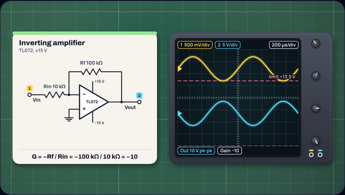
Two consequences matter in practice. The source sees Rin and nothing else, because the other end of Rin sits at 0 V: the input impedance is 10 kΩ here, which a weak source will notice. And the gain can be anything, including less than 1: Rf = 4.7 kΩ with Rin = 10 kΩ gives −0.47, an attenuator that can also drive a load.
How does a non-inverting amplifier get its gain?
Now the signal goes straight into the non-inverting input, and Rf and Rg form a voltage divider from the output to ground, with the inverting input at the middle. The divider puts a fraction of the output on the inverting input:
The op amp drives the output until that equals . Solve for the output and the divider ratio flips over:
Example 2: the same resistors, non-inverting
That "1 +" is the whole difference between the two answers in the opening. The divider can feed back at most the full output, so the gain can never drop below 1. Leave Rg out and replace Rf with a wire, and the gain is exactly 1: the voltage follower, or buffer, used to let a weak source drive a heavy load. Because the signal only meets an op amp input, which draws almost no current, the source sees a very high impedance.
Which should you use?
The two circuits share everything except where the signal enters. This table sets them side by side.
| Inverting | Non-inverting | |
|---|---|---|
| Gain | −Rf / Rin | 1 + Rf / Rg |
| Smallest gain | Any, including below 1 | 1 |
| Polarity | Flipped | Kept |
| Input impedance | Rin | Very high |
| Voltage on the inputs | Fixed at the reference | Follows the signal |
| Noise gain | 1 + Rf / Rin | 1 + Rf / Rg |
Pick non-inverting when the source is weak, such as a sensor, a guitar pickup or a microphone capsule, or when the polarity matters. Pick inverting when you want to attenuate, to add several signals (each through its own Rin into the same virtual ground), or to keep the op amp's inputs at a fixed voltage. That last point matters because no op amp rejects a common voltage on its inputs perfectly, and in the inverting circuit that voltage does not move with the signal.
How do you choose standard resistor values?
Start with the input or ground resistor, often somewhere between 1 kΩ and 100 kΩ, then solve for Rf and round it to a value you can buy. Very low values make the op amp drive a heavy load through the feedback network; very high ones add noise and turn the inputs' bias current into an offset.
Example 3: a non-inverting gain of exactly 10
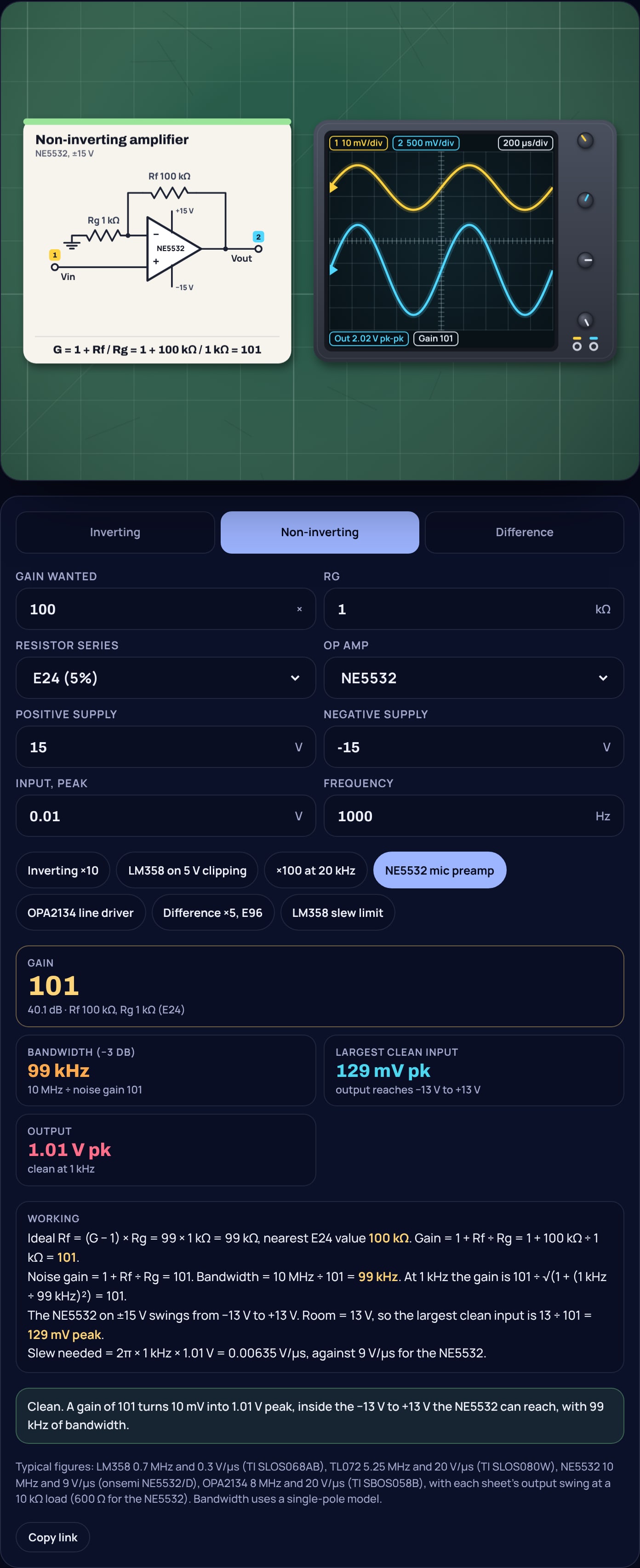
90 kΩ is not in the E24 series, so the obvious choice lands 1% high. Moving Rg instead solves it: 180 kΩ ÷ 20 kΩ is exactly 9. The calculator tries every input resistor from 1 kΩ to 100 kΩ in the series you choose and lists the pairs that come closest.
The same "1 +" catches people the other way. A microphone preamp with Rg = 1 kΩ and a round 100 kΩ for Rf has a gain of 101, not 100. That is harmless in audio, but it explains why a test reading is 1% off when nothing is wrong.
Where does the difference amplifier fit in?
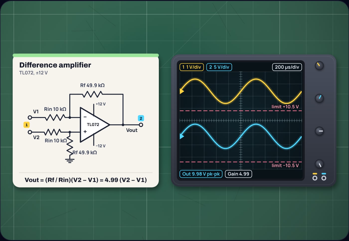
Use both inputs at once and you get a difference amplifier. V1 goes through Rin to the inverting input with Rf as feedback, as before. V2 goes through a second Rin to the non-inverting input, with a second Rf from there to ground. If the two pairs match, everything the inputs have in common cancels:
With 10 kΩ and 49.9 kΩ from the E96 series, the gain is 4.99. The exact value matters less than the match. If one ratio is off by 1%, part of the voltage the inputs share leaks into the output, which is why this circuit is built with 1% or better resistors, or bought as a single part with matched resistors on the chip.
Why does the output clip before the supply?
The gain formula assumes the output can go wherever it is told. It cannot get past the supply, and most op amps stop well short of it. Each datasheet gives the limit:
- TI's TL072 sheet gives a typical peak output of ±13.5 V on ±15 V into 10 kΩ.
- onsemi's NE5532 sheet gives ±13 V typical into 600 Ω.
- TI's OPA2134 sheet gets to within 1.2 V of the positive rail and 0.5 V of the negative rail at 10 kΩ.
- TI's LM358 sheet gives 2 V typical below the positive rail at 30 V (1.5 V maximum at 5 V), but only 5 mV above the negative rail.
That last one is why the LM358 is popular on single supplies, and also why it runs out of room quickly at the top.
Example 4: an LM358 on a single 5 V supply
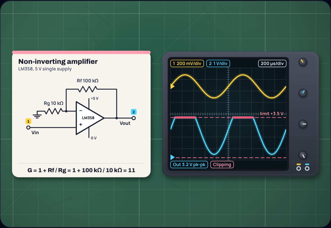
Non-inverting gain of 11, output biased at half the supply, 2.5 V. The output can reach about 3.5 V.
Feed it 0.2 V peak and the output wants to reach 2.5 + 2.2 = 4.7 V. It stops at 3.5 V, so the top of every cycle is cut flat while the bottom still has room. On a scope that one-sided flattening is the signature of running out of headroom on one rail.
Do the two circuits have the same bandwidth?
With the same resistors, yes, and this is where the "1 +" turns up again. An op amp's speed is set by its gain bandwidth product, and the bandwidth of a stage is that product divided by the noise gain, the gain the feedback network sets for the op amp itself. In both circuits the noise gain is .
So an LM358, at 0.7 MHz typical in TI's datasheet, gives 0.7 MHz ÷ 11 = 63.6 kHz with 10 kΩ and 100 kΩ, whether you wire it for −10 or for 11. The non-inverting version gets one more unit of gain for the same bandwidth. The full story, including why a gain of −1 has half the bandwidth of a buffer, is in our guide to gain bandwidth product.
Example 5: an inverting gain of 100 at 20 kHz
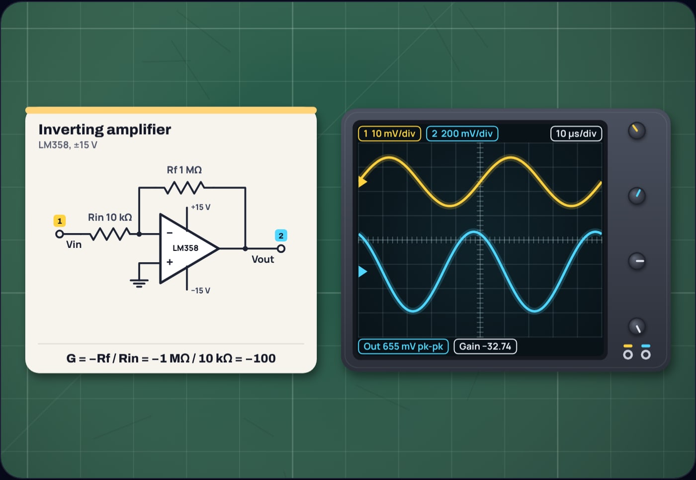
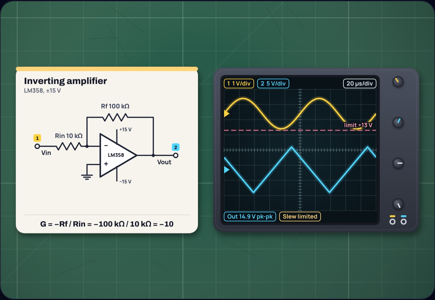
Large signals meet a second speed limit, the slew rate. An LM358 at 0.3 V/µs cannot swing a 10 V peak sine faster than about 4.8 kHz, and above that the sine turns into a triangle. Both limits are explained in the gain bandwidth guide; the calculator checks both and draws the result.
What does the calculator show?
Choose inverting, non-inverting or difference, type the gain you want and the input resistor, and the op amp gain calculator picks the nearest E24 or E96 feedback resistor, works the real gain back out and lists closer pairs. Choose an LM358, TL072, NE5532 or OPA2134 and a supply, and it gives the bandwidth, the largest input before clipping and the slew rate your signal needs. The scope shows the input and output with the output limits dashed and any clipped stretch marked in red.
The transistor inside each op amp is a story of its own, told in how a transistor amplifies. And if the roll-off above the bandwidth looks familiar, it is the same single-pole curve as an RC low-pass filter.
Sources
- Texas Instruments, LMx58 and LM2904 datasheet, SLOS068AB, revised October 2024 (LM358 gain bandwidth product 0.7 MHz, slew rate 0.3 V/µs, output swing from the rails, open-loop gain, supply range): ti.com/lit/ds/symlink/lm358.pdf
- Texas Instruments, TL07xx datasheet, SLOS080W, revised July 2025 (gain bandwidth product 5.25 MHz, or 3 MHz for NS and PS packages and the M grade, slew rate 20 V/µs, maximum peak output ±13.5 V typical): ti.com/lit/ds/symlink/tl072.pdf
- onsemi, NE5532 datasheet, NE5532/D, Rev. 2, September 2013 (gain bandwidth product 10 MHz, slew rate 9 V/µs, output swing ±13 V typical into 600 Ω): onsemi.com/pdf/datasheet/ne5532-d.pdf
- Texas Instruments, NE5532 datasheet, SLOS075K, revised December 2025 (12 MHz unity-gain bandwidth, 5 V/µs, recommended supplies ±5 to ±15 V): ti.com/lit/ds/symlink/ne5532.pdf
- Texas Instruments, OPAx134 datasheet, SBOS058B, revised November 2024 (gain bandwidth product 8 MHz, slew rate 20 V/µs, output swing from the rails): ti.com/lit/ds/symlink/opa2134.pdf
- Vishay, Standard Series Values in a Decade, E3 to E192 according to IEC 60063, document 28372 (E24 and E96 resistor values): vishay.com/docs/28372
Frequently asked questions
What is the gain formula for an inverting amplifier?
Gain = −Rf / Rin, where Rin runs from the input to the inverting input and Rf from the output back to the inverting input. The minus sign means the output is upside down. Rin = 10 kΩ and Rf = 100 kΩ give a gain of −10.
What is the gain formula for a non-inverting amplifier?
Gain = 1 + Rf / Rg, where Rf runs from the output to the inverting input and Rg from the inverting input to ground. The signal goes into the non-inverting input. Rf = 100 kΩ and Rg = 10 kΩ give a gain of 11.
Why can a non-inverting amplifier not have a gain below 1?
Its output has to be at least as large as its input, because the feedback divider can only feed back a fraction of the output and the op amp drives the output until that fraction equals the input. With no divider at all, the gain is exactly 1, which is a voltage follower.
Which is better, inverting or non-inverting?
Neither in general. The non-inverting amplifier has a very high input impedance and keeps the signal’s polarity. The inverting amplifier has an input impedance equal to Rin, can attenuate as well as amplify, and its inputs sit at a fixed voltage, which keeps common-mode error out of the signal.
Do inverting and non-inverting amplifiers have the same bandwidth?
With the same resistors, yes. Both have a noise gain of 1 + Rf/Rin, and bandwidth is the gain bandwidth product divided by the noise gain. An LM358 at 0.7 MHz with 10 kΩ and 100 kΩ gives 63.6 kHz either way, for a gain of −10 inverting or 11 non-inverting.