How do you set the LM317 output voltage?
Choose R1, usually 240 Ω, then R2 from Vout = 1.25 × (1 + R2 / R1) + Iadj × R2. For 5 V with R1 = 240 Ω the ideal R2 is 713 Ω; the nearest E24 value, 680 Ω, gives 4.83 V. The input must be at least 3 V above the output, and every volt of difference times the load current becomes heat in the regulator.
The calculator does all three steps and shows other standard pairs that land closer. For the derivation, worked examples and the mistakes that cook regulators, read the LM317 formula explained.
Key LM317 figures from the TI datasheet
- Reference 1.25 V between OUT and ADJ, between 1.2 and 1.3 V from part to part and over temperature, which sets how accurate the output can be without trimming.
- Adjust pin current 50 µA typical. It flows through R2 and adds 34 mV to a 5 V design with R2 = 680 Ω.
- Headroom up to 3 V between input and output, and no more than 40 V. Output from 1.25 to 37 V, current up to 1.5 A.
- Junction limit 125 °C. In TI's thermal table the TO-220 (KCS) is 23.5 °C/W junction to air and the SOT-223 66.8 °C/W.
Seven LM317 designs
Each loads the breadboard with the resistors, input and load, and shows the meter reading and how hot the regulator runs.
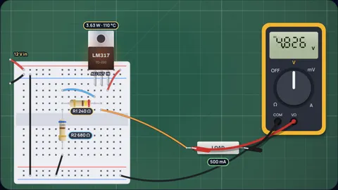
5 V at 500 mA from a 12 V supply
R2 680 ΩWith R1 = 240 Ω, R2 = 680 Ω gives 4.83 V. The reference tolerance alone spreads that from 4.63 to 5.05 V, so a 5% resistor pair is as good as the chip anyway. The closest E24 pair overall is 510 Ω and 1.5 kΩ at 5.001 V.
The regulator drops 7 V at about 0.505 A, 3.6 W of heat. A TO-220 at 23.5 °C/W in 25 °C air reaches about 110 °C: inside the limit, but hot to touch. A switching regulator would waste far less.
Why 3.3 V from 5 V does not work
DropoutThe resistors are easy, 240 Ω and 390 Ω for 3.3 V, but there is only 1.7 V between input and output. TI's datasheet says the LM317 needs up to 3 V to stay in regulation.
At low current and room temperature it may limp along, but the output will follow the input down as the load grows. For this job use a low-dropout regulator.
12 V at 1 A from 24 V needs a heat sink
12.3 WR1 = 240 Ω and R2 = 2 kΩ give 11.77 V. The regulator drops 12.2 V at about 1 A, so it must shed 12.3 W.
Without a heat sink the junction would climb to about 314 °C, far past 125 °C; thermal shutdown would cut in long before. To stay at the limit in 25 °C air, the total path from junction to air must be under 8.1 °C/W, which needs a real heat sink and a thermal pad.
9 V with 1% resistors
8.98 VE96 gives more choices: with R1 = 240 Ω, R2 = 1.47 kΩ gives 8.98 V.
Even so, the 1.2 to 1.3 V reference range moves the output between 8.62 and 9.41 V. Precise resistors only pay off if you trim the output or pick parts.
1.8 V from 5 V in a SOT-223
73 °CFor a low output, R2 is small: 100 Ω with R1 = 240 Ω gives 1.78 V, and the headroom of 3.2 V is fine.
The SOT-223 is 66.8 °C/W in TI's table, so 0.5 W in 40 °C air puts the junction near 73 °C. A larger copper area under the tab lowers that.
A 350 mA constant-current LED driver
3.6 ΩIn current mode a single resistor goes from OUT to ADJ, and the load hangs from ADJ. The regulator keeps 1.25 V across the resistor, so R = 1.25 / 0.35 = 3.57 Ω; the nearest E24 value, 3.6 Ω, gives 347 mA.
The resistor dissipates 0.43 W, and the regulator drops what is left of the supply: with a 9 V load on 15 V, 1.65 W.
TI's 50 mA battery charger
24 ΩTI's datasheet shows a trickle charger with a 24 Ω resistor: 1.25 V ÷ 24 Ω = 52 mA. It also states the input must exceed the battery voltage plus 4.25 V, the 1.25 V reference plus 3 V of headroom.
For a 6 V battery that means at least 10.25 V in.
R2 for common outputs with R1 = 240 Ω
| Output | Ideal R2 | E24 R2 | Gives |
|---|---|---|---|
| 1.8 V | 105 Ω | 100 Ω | 1.78 V |
| 2.5 V | 238 Ω | 240 Ω | 2.51 V |
| 3.3 V | 390 Ω | 390 Ω | 3.3 V |
| 5 V | 713 Ω | 680 Ω | 4.83 V |
| 6 V | 903 Ω | 910 Ω | 6.04 V |
| 9 V | 1,474 Ω | 1.5 kΩ | 9.14 V |
| 12 V | 2,044 Ω | 2 kΩ | 11.77 V |
| 15 V | 2,615 Ω | 2.7 kΩ | 15.45 V |
| 24 V | 4,326 Ω | 4.3 kΩ | 23.86 V |
Including the 50 µA adjust current. The 1.2 to 1.3 V reference tolerance moves every output by about ±4%, so for exact values add a trimmer or measure and adjust.
How the calculator works
Voltage mode solves the datasheet equation for R2 with your R1, rounds it to the nearest E24 or E96 value and works the output back out, including the 50 µA adjust current. It also searches R1 from 100 Ω to 1 kΩ for the pairs that land closest to your target.
The regulator current is the load plus the divider current, 1.25 V ÷ R1. Power is the input to output difference times that current, plus the input voltage times the adjust current, as in TI's heat sink section.
Junction temperature is air temperature plus power times the package's junction to air thermal resistance from TI's table. If that passes 125 °C, the calculator gives the thermal resistance a heat sink must reach.
Current mode sets R = 1.25 V ÷ I to the nearest series value and checks that the input covers the load voltage plus 4.25 V.
What the model leaves out
- Ripple and transients. Input and output capacitors and the optional 10 µF adjust capacitor improve ripple rejection; see TI's datasheet for values.
- Board copper. Thermal resistance figures assume TI's test board. A large copper pour or a real heat sink lowers them a lot; a cramped enclosure raises them.
- Protection diodes. When output or adjust capacitors are fitted, TI recommends diodes that give them a safe discharge path.
- Other versions. TI's comparison table lists the LM317HV for inputs up to 60 V and the LM317A with tighter load regulation; the limits here are for the LM317.
Common misconceptions
"It needs only about 1 V of headroom." TI asks for up to 3 V for guaranteed regulation. Low-dropout parts exist for the cases where you have less.
"A bigger R1 saves power." It does slightly, but the LM317 also needs a minimum load current, up to 10 mA in TI's table. With no load, too large an R1 lets the output drift up.
"Linear regulators are efficient enough." Efficiency is roughly Vout ÷ Vin. 5 V from 12 V wastes more than half the input power as heat.
Frequently asked questions
What is the LM317 formula?
Vout = 1.25 × (1 + R2 / R1) + Iadj × R2, where 1.25 V is the reference and Iadj is about 50 µA. With R1 = 240 Ω and R2 = 680 Ω, Vout is 4.83 V.
Why is R1 usually 240 Ω?
TI uses 240 Ω in its circuits. 1.25 V across 240 Ω draws about 5.2 mA, which helps cover the minimum load current the regulator needs to hold its output.
What input voltage does an LM317 need?
At least the output plus up to 3 V of headroom, and no more than 40 V above the output. For 5 V out, plan on 8 V or more in.
Does the LM317 need a heat sink?
It depends on the power: (Vin minus Vout) times the current. In TI's table a TO-220 (KCS) is 23.5 °C/W to air, so in 25 °C air it reaches 125 °C at about 4.3 W. Above that, it needs a heat sink.
How do I make a constant current source with an LM317?
Put one resistor between OUT and ADJ and take the current from ADJ. The current is 1.25 V divided by the resistor: 3.6 Ω gives about 347 mA.
Keep learning
LM317 Formula Explained, With Worked Examples
Vout = 1.25(1 + R2/R1) + Iadj R2. Where the LM317 formula comes from, how to pick R1 and R2, why it needs 3 V of headroom and when it needs a heat sink.

Why Do LEDs Need a Resistor? The I-V Curve Explained
An LED's current rises exponentially with voltage: 0.1 V extra takes a red LED from 20 mA to 56 mA. Here is the physics, the resistor math and the fixes.
Zener Diode Resistor Calculation: The Worst-Case Method
R = (Vin − Vz)/Iz is half the job. Size the zener resistor at minimum input and full load, then check the zener at no load. Worked 12 V to 5.1 V example.

Why Phone Charging Slows After 80%: The CC-CV Curve
Fast charging fills a phone from 0 to 70% at full current, then a fixed voltage limit makes the current taper. The physics, the plating risk and the math.