LM317 Formula Explained, With Worked Examples

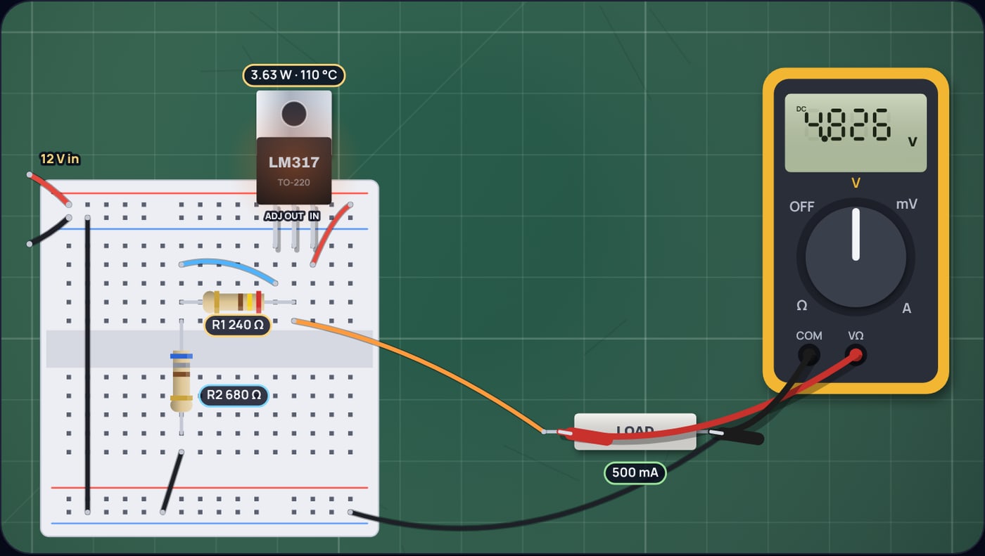
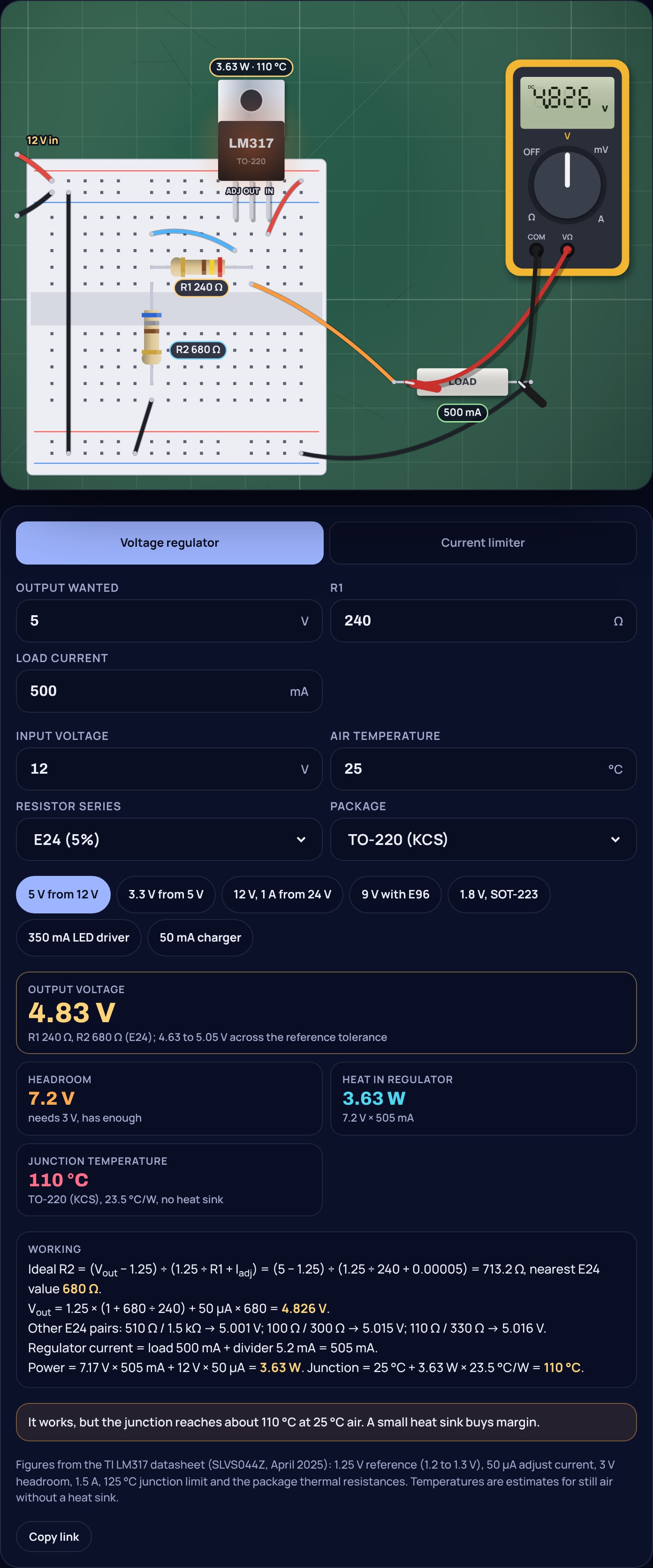
Put 12 V into an LM317, add a 240 Ω and a 680 Ω resistor, and a meter on the output reads about 4.83 V. Swap the 680 Ω for a 750 Ω and it reads about 5.19 V. Nothing else about the circuit changes. Those two resistors, plus one number built into the chip, decide the output, and the formula that ties them together fits on one line.
This guide derives that formula from what the chip actually does, works through five real designs with the figures from TI's current datasheet, and covers the two things the formula does not tell you: how much input voltage you need and how hot the part will get. Our LM317 calculator runs every one of these checks and picks standard resistor values for you.
Where does the LM317 formula come from?
The LM317 does one thing: it adjusts its output until the OUT pin sits 1.25 V above the ADJ pin. TI's datasheet calls this the reference voltage, 1.25 V typical, and describes the device as sourcing whatever current is needed "to make the OUTPUT pin 1.25V greater than ADJUST pin".
Put R1 between OUT and ADJ and that 1.25 V sits across it, so a current of 1.25 V ÷ R1 flows through it. That current has nowhere to go but down through R2 to ground, joined by the small current that leaks out of the ADJ pin, . The output is the voltage across R2 plus the 1.25 V on top:
Multiply out and you get the form printed in the datasheet as Equation 2:
How do you choose R1 and R2?
Start with R1. TI uses 240 Ω in its example circuits, and there is a reason: the regulator needs a minimum load current to hold its output, up to 10 mA in TI's table, and 1.25 V across 240 Ω draws about 5.2 mA through the divider even with nothing connected. Then solve the formula for R2:
Example 1: 5 V with R1 = 240 Ω
713 Ω is not a value you can buy. The nearest in the E24 series are 680 Ω and 750 Ω:
Example 2: what each standard value gives
Neither is exactly 5 V, and you have three ways out. Use 1% resistors: 715 Ω from the E96 series lands within about 10 mV. Change R1 as well: the calculator searches R1 from 100 Ω to 1 kΩ and finds, for example, 510 Ω with 1.5 kΩ at 5.001 V. Or fit a trimmer for R2 and set it with a meter.
Before chasing millivolts, look at the chip itself. TI specifies the reference between 1.2 and 1.3 V across parts, load and temperature, and the adjust current up to 100 µA. With 240 Ω and 680 Ω, those limits alone move the output from about 4.63 to 5.05 V. Precise resistors cannot fix that; only trimming can.
Does the adjust pin current matter?
Usually not much. TI's datasheet says "is typically 50µA and negligible in most applications". It flows only through R2, so its effect grows with R2. With R2 = 680 Ω it adds 34 mV, under 1% of a 5 V output. With R2 = 4.3 kΩ for a 24 V supply it adds 0.2 V, which starts to show. That is another reason to keep R1, and therefore R2, small: the divider current then swamps the adjust current.
Why does 3.3 V from 5 V not work?
The formula is happy with any output, but the chip is not. TI's datasheet states that the device "requires up to 3V headroom" between input and output "to operate in regulation", and its recommended operating conditions list an input to output difference of 3 to 40 V. Making 3.3 V from a 5 V rail leaves 1.7 V.
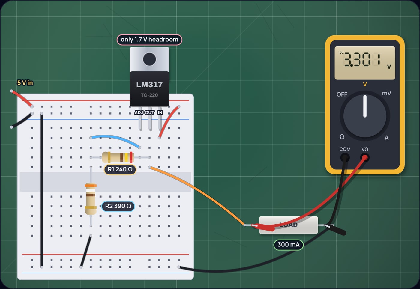
At light load on the bench it may appear to work, which is what makes this mistake persistent. Under a real load the output follows the input down, and any ripple on the 5 V rail comes straight through. The fix is a low-dropout regulator, which is built to work with a few hundred millivolts of headroom.
How hot does an LM317 get?
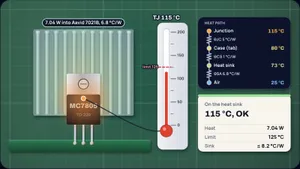
A linear regulator gets rid of the extra voltage by turning it into heat. TI's heat sink section gives the power as the voltage across the regulator times the load current, plus a small term for the adjust current:
The junction then sits above the air by that power times the package's thermal resistance. TI's thermal table gives 23.5 °C/W for the TO-220 (KCS), 38.0 °C/W for the TO-263 and 66.8 °C/W for the SOT-223, junction to air on a standard test board. The junction must stay below 125 °C.
Example 3: 5 V at 500 mA from 12 V
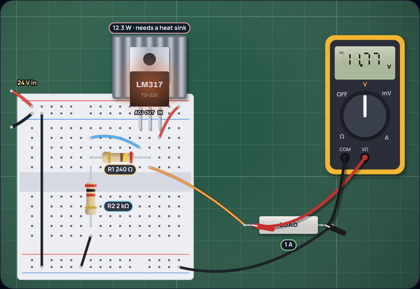
That is inside the limit, just. Now try 12 V at 1 A from a 24 V supply: 12.3 V across the chip at about 1 A is 12.3 W, and 12.3 × 23.5 adds nearly 290 °C to the air temperature. The chip's thermal protection would shut it down long before. To hold 125 °C in 25 °C air, the whole path from junction to air must be under about 8.1 °C/W, which takes a proper finned heat sink with a thermal pad.
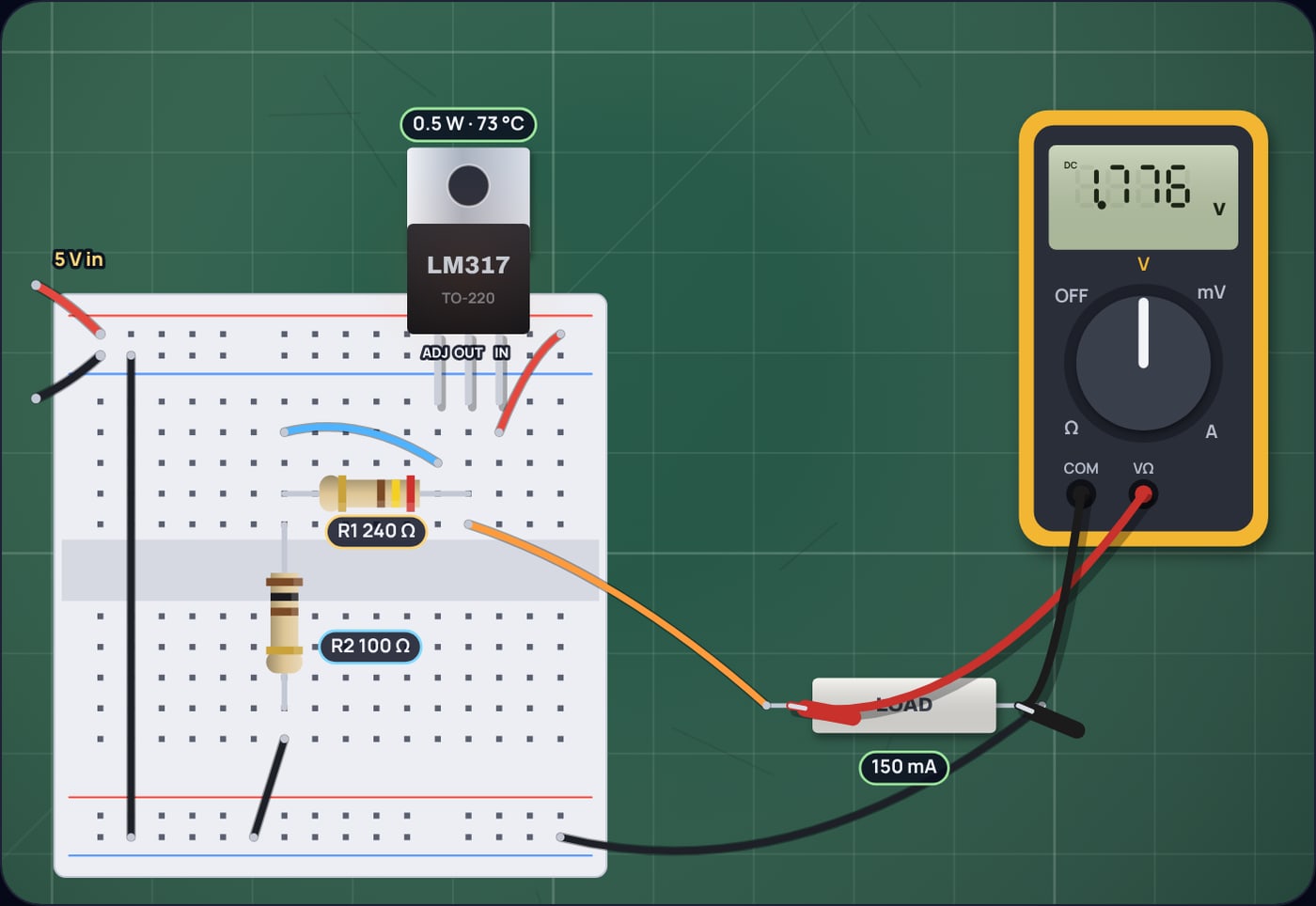
Small packages fill up even faster. A SOT-223 at 66.8 °C/W making 1.8 V from 5 V at 150 mA in 40 °C air sheds only half a watt, yet its junction reaches about 73 °C. A bigger copper area under its tab helps, because on a surface-mount part the board is the heat sink.
How do you make a constant current source?
Drop R2 and move the load. With one resistor R from OUT to ADJ and the load connected from ADJ to ground, the chip still keeps 1.25 V across R, so the current through it, and through the load, is fixed:
TI shows this as its precision current limiter, and uses it for a 50 mA battery charger with a 24 Ω resistor: 1.25 ÷ 24 is about 52 mA. The datasheet also gives the input it needs: the battery voltage plus 4.25 V, which is the 1.25 V across the resistor plus the usual 3 V of headroom.
Example 4: a 350 mA LED driver
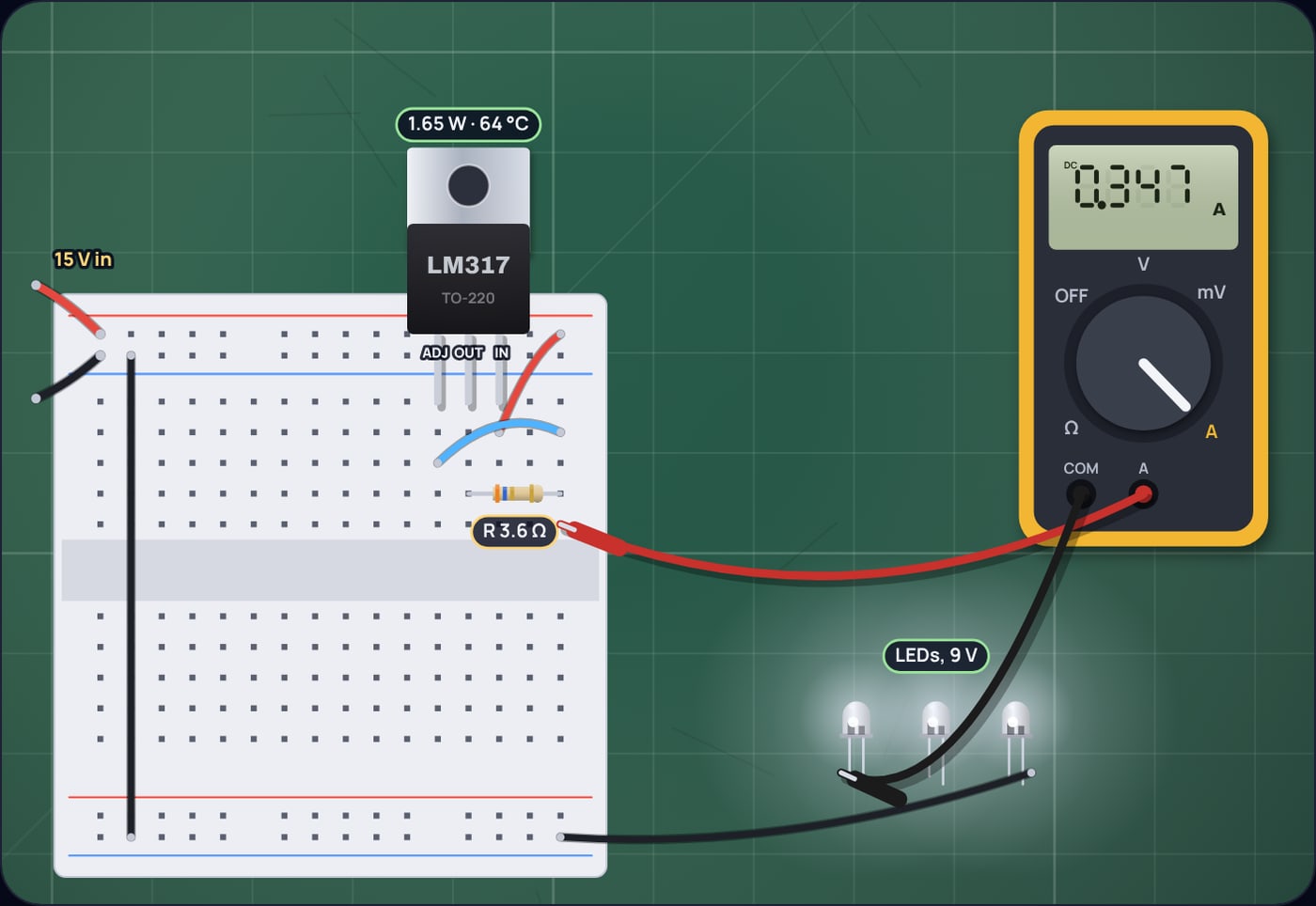
Choose the resistor's power rating with margin: 0.43 W calls for at least a 1 W part. The regulator heats up too, by the leftover voltage times the current; with a 9 V LED string on 15 V that is about 1.65 W. For why LEDs need a set current in the first place, see why LEDs need a resistor, and for a simpler shunt regulator, our guide to choosing a zener diode resistor.
What does the calculator show?
Type the voltage you want, the input and the load, and the LM317 calculator solves for R2, rounds it to E24 or E96, works the real output back out and lists other pairs that land closer. It checks the 3 V headroom, the 40 V limit and the 1.5 A rating, and estimates the junction temperature for the package you pick. When that passes 125 °C, it tells you how good a heat sink must be.
Sources
- Texas Instruments, LM317 3-Pin Adjustable Regulator datasheet, SLVS044Z, revised April 2025 (Equation 2, reference voltage 1.2 to 1.3 V, adjust current 50 to 100 µA, 3 V headroom, recommended operating conditions, minimum load current, thermal information, heat sink equations, current limiter and 50 mA charger circuits): ti.com/lit/ds/symlink/lm317.pdf
- Vishay, Standard Series Values in a Decade, E3 to E192 according to IEC 60063, document 28372 (E24 and E96 resistor values): vishay.com/docs/28372
Frequently asked questions
What is the LM317 output voltage formula?
Vout = 1.25 × (1 + R2 / R1) + Iadj × R2. The 1.25 V is the reference the chip holds between its OUT and ADJ pins, R1 runs from OUT to ADJ, R2 from ADJ to ground, and Iadj is the adjust pin current, about 50 µA.
What R2 do I need for 5 V with an LM317?
With R1 = 240 Ω the exact R2 is about 713 Ω once the 50 µA adjust current is included. The nearest standard E24 value, 680 Ω, gives about 4.83 V; 750 Ω gives about 5.19 V. A 1% E96 resistor of 715 Ω lands within about 10 mV of 5 V.
How much input voltage does an LM317 need?
TI’s datasheet says the LM317 needs up to 3 V between input and output to stay in regulation, and no more than 40 V. So for 5 V out, plan on at least 8 V in.
When does an LM317 need a heat sink?
When the heat it must shed, (Vin minus Vout) times the current, would push the junction past 125 °C. In TI’s thermal table a TO-220 (KCS) package is 23.5 °C/W to air, so at 25 °C air it reaches the limit at about 4.3 W.
How do you use an LM317 as a current source?
Connect one resistor between OUT and ADJ and take the current from the ADJ end. The chip keeps 1.25 V across the resistor, so the current is 1.25 V divided by its value: 24 Ω gives about 52 mA, 3.6 Ω about 347 mA.