32.768 kHz Crystal Not Starting or Running Slow? Fixes
A real-time clock that loses a second and a half a day is not broken. A board where the clock runs on the bench but stays at 00:00:00 on a cold morning is not cursed either. Both are the 32.768 kHz crystal telling you that the two little capacitors next to it, and the copper around them, do not suit it. The crystal itself is almost never the problem.
This guide works through both failures with the formulas in ST's oscillator design guide, AN2867, and figures from real watch crystal datasheets. Our crystal load capacitor calculator runs every check below for your own parts. If you want the general derivation of the load capacitor formula first, it is in how to calculate crystal load capacitors.
What does the crystal need from the circuit?
A microcontroller drives its 32.768 kHz crystal with a Pierce oscillator: an inverting amplifier between OSC_IN and OSC_OUT, the crystal across the same two pins, and a capacitor from each pin to ground. Two things have to be right.
- The amplifier must have enough gain to make up for the crystal's losses, or the oscillation never builds up.
- The capacitance the crystal sees must match the load it was trimmed for, or it runs at the wrong frequency.
Both depend on the same quantity, the load capacitance. AN2867 defines it as
where CL1 and CL2 are the capacitors you fit and Cs is "the addition of the microcontroller pin capacitance (OSC_IN and OSC_OUT) and the PCB capacitance". With equal capacitors that becomes .
Why does the oscillator not start?
The crystal's losses are its equivalent series resistance, and watch crystals have a lot of it. Rakon's RTF2012 datasheet gives 80 kΩ maximum; Abracon's ABS07 gives 70 kΩ. AN2867 turns that into the minimum transconductance the oscillator must supply:
and asks for a gain margin, gm ÷ gmcrit, of at least 5. Below that, ST warns, "the oscillation might start up under typical conditions (achieved in laboratory conditions)" but there is no guarantee in operating conditions. That is the bench versus cold morning problem in one sentence.
The square of C0 + CL is what bites. Here is gmcrit for an 80 kΩ crystal with a shunt capacitance C0 of 1 pF (within the ABS07's typical range of 0.9 to 1.2 pF) at the four load ratings sold for watch crystals:
| Crystal CL | gmcrit | gm needed for a margin of 5 |
|---|---|---|
| 6 pF | 0.66 µA/V | 3.3 µA/V |
| 7 pF | 0.87 µA/V | 4.3 µA/V |
| 9 pF | 1.36 µA/V | 6.8 µA/V |
| 12.5 pF | 2.47 µA/V | 12.4 µA/V |
Low-power oscillators do not have much to give. AN2867's table of STM32 LSE oscillators lists, for the STM32L0 and L4, a minimum gm of 2.5, 3.75, 8.5 and 13.5 µA/V for the low, medium-low, medium-high and high drive settings.
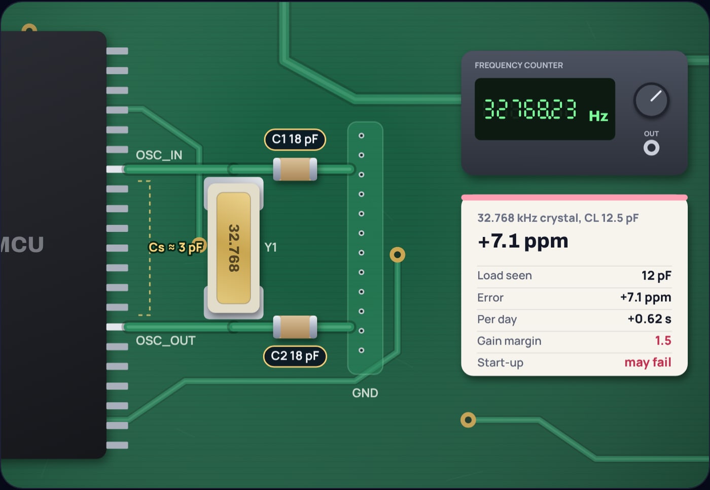
Example 1: a 12.5 pF crystal on medium-low drive
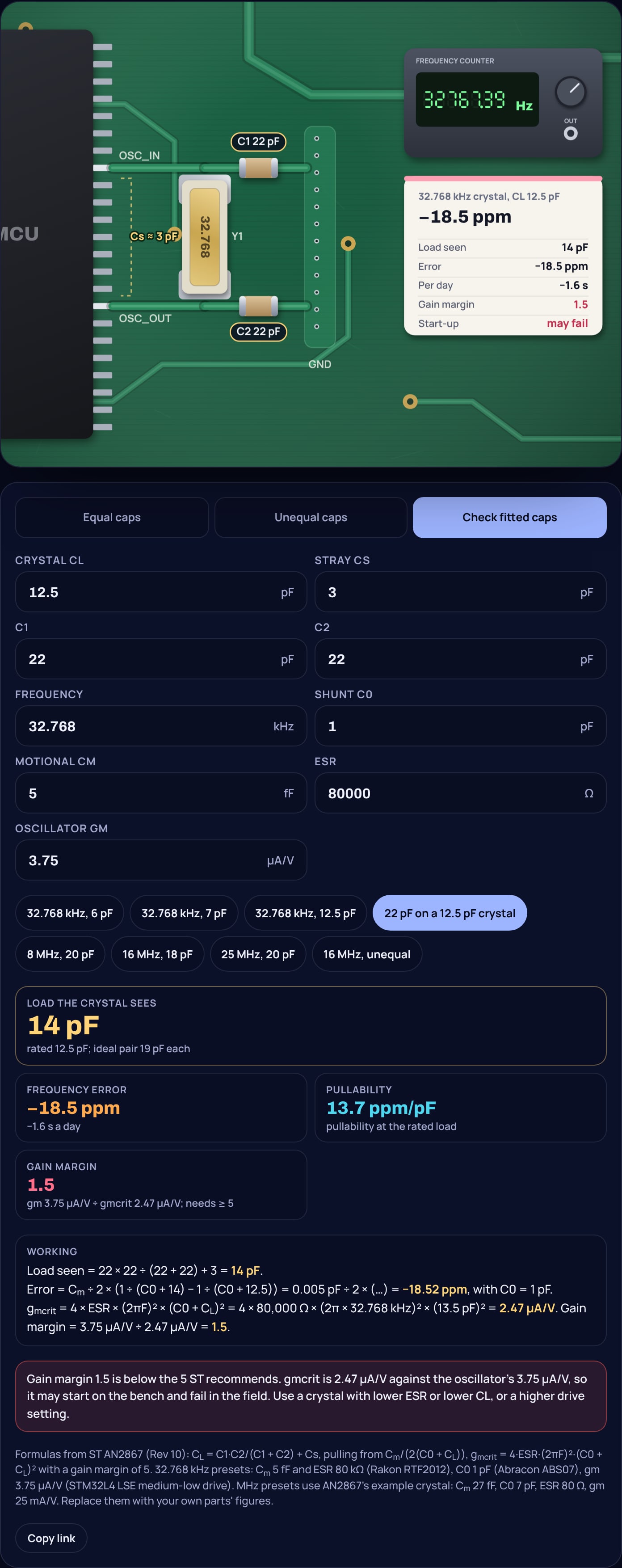
A margin of 1.5 may well oscillate on your desk. It is exactly the design that stops working on some boards, at some temperatures, as the crystal ages. A 6 pF version of the same crystal needs only 0.66 µA/V and reaches a margin of 5.6 on the same setting. AN2867 makes the same point from the other side: on the STM32F0 and F3, the high drive mode should be used only with 12.5 pF crystals.
So the fixes for "will not start", in the order they usually help:
- Use a higher drive setting, if your microcontroller has one.
- Choose a crystal with a lower load rating, 6 or 7 pF, or a lower ESR.
- Do not fit capacitors larger than the formula gives. Extra capacitance raises the load the crystal sees, and with it gmcrit.
- Wait long enough. AN2867 says the start-up time of a 32.768 kHz crystal "ranges from 1 to 5 s". Firmware that gives up after 100 ms will report a failure that is not there.
One more trap: an oscilloscope probe on OSC_IN or OSC_OUT adds its own capacitance to that pin. AN2867 includes the probe capacitance in its own measurement formula for this reason. A clock that stops when you probe it may simply be marginal.
Why does the clock run slow?
A crystal oscillating in a Pierce circuit runs slightly above its series resonance, by an amount set by the load. AN2867 gives the frequency as
where Cm is the motional capacitance, 5.0 fF for the RTF2012. More load capacitance means a smaller fraction, so the crystal runs slower. The manufacturer trims it to read exactly 32,768 Hz at its rated CL; any other load moves it off.
The most common way to get this wrong is to copy the 22 pF capacitors from a reference design for a different crystal.
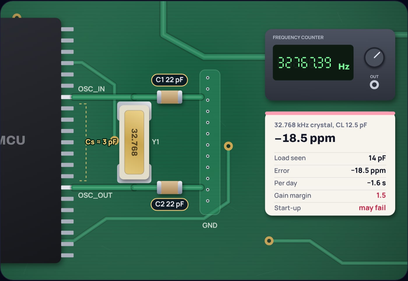
Example 2: 22 pF caps on a 12.5 pF crystal, 3 pF of stray
One ppm is 0.0864 s a day, so this clock loses about 1.6 s a day, close to 48 s a month.
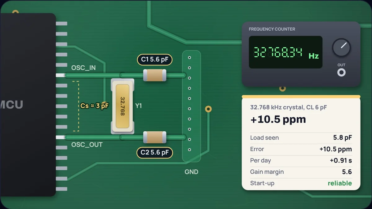
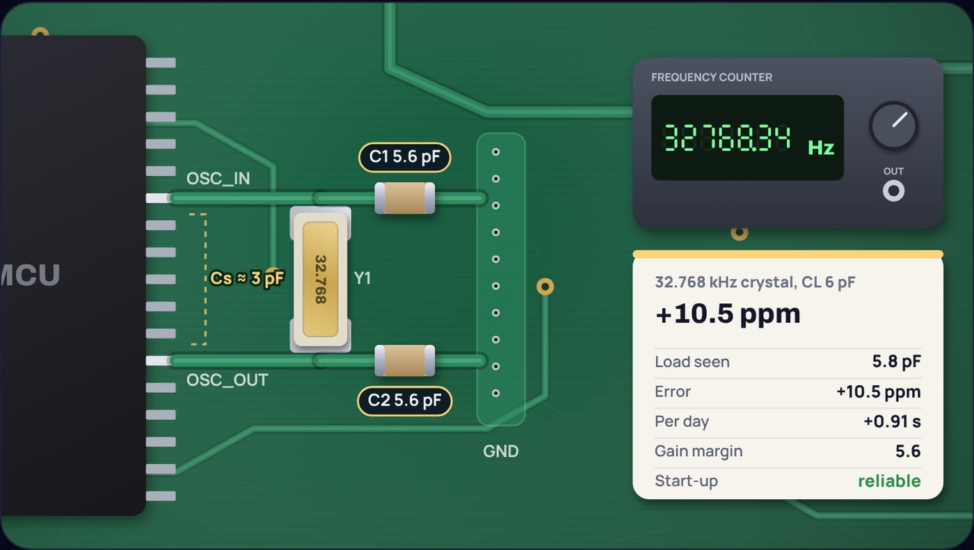
The same 22 pF on a 6 pF crystal is far worse. It sees 14 pF instead of 6, about 190 ppm slow, or 16 s a day. The right value for it, with 3 pF of stray, is 2 × (6 − 3) = 6 pF, and the nearest E12 part, 5.6 pF, leaves it 10.5 ppm fast, under a second a day.
Why are low-load crystals so sensitive?
AN2867 defines pullability, the shift per picofarad of load, as
Again CL is squared. With Cm = 5 fF and C0 = 1 pF, a 12.5 pF crystal moves 13.7 ppm per pF and a 6 pF crystal 51 ppm per pF. A single picofarad of unexpected trace capacitance costs the 6 pF crystal about 45 ppm, nearly 4 s a day.
AN2867 works its own example with a 45 ppm/pF crystal and two 7 pF C0G capacitors of ±5% tolerance: the series pair moves the load by 0.175 pF, which shifts the frequency by about 7.8 ppm, "~0.7 s/day for a time-keeping function such as RTC". That is the error from capacitor tolerance alone.
So there is a real trade. The low-load crystal that solves the start-up problem is the one that punishes a wrong guess of stray capacitance. That makes the stray estimate the number to get right.
How much stray capacitance should you assume?
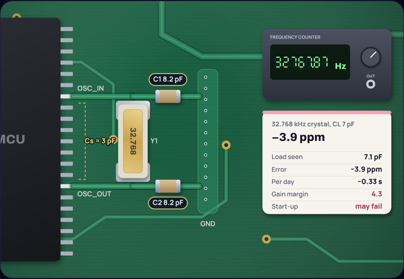
ST's own guidance, in a 2025 knowledge article on choosing STM32 crystals, is that "Experience has shown that the value is between 2...3 pF", and it notes that the 5 pF pin capacitance in most STM32 datasheets is a generic worst case. AN2867's worked example uses 5 pF. The calculator lets you change it; 3 pF is a sensible start for a compact layout with short traces.
Then measure. Build one board, measure the frequency without loading the oscillator pins, and adjust the capacitors. A higher reading than 32,768 Hz means too little load, so increase the capacitors; a lower reading means too much.
Is the crystal itself ever the problem?
Sometimes the error is not in the capacitors at all. Both datasheets used here give a tolerance of ±20 ppm at 25 °C, up to 1.7 s a day before anything else. Tuning fork crystals also slow down on both sides of their turnover temperature: ABS07 gives −0.036 ppm/°C² around 25 °C, so at 0 °C the crystal is about 22.5 ppm slow, close to 2 s a day. That curve is covered in why watch crystals run at 32,768 Hz.
If your clock is slow by a steady amount at room temperature, look at the load capacitors first. If it drifts with the seasons, look at temperature. If it is off by tens of ppm and the capacitors are right, measure the stray.
How do you check your own design?
Put the crystal's CL, C0, motional capacitance and ESR into the crystal load capacitor calculator, with your estimate of stray and your oscillator's gm. It gives the capacitors and the nearest standard values, the ppm and seconds a day the fitted pair cost, the pullability, and the gain margin against ST's factor of 5. Check fitted caps mode does the reverse for a board you already have.
Sources
- STMicroelectronics, AN2867, Oscillator design guide for STM8S, STM8A and STM32 microcontrollers, DocID15287 Rev 10, August 2015 (load capacitance formula and Cs definition, load frequency equation, gmcrit and the gain margin of 5, 32.768 kHz start-up time of 1 to 5 s, pullability formula and 7.8 ppm example, STM32 LSE gm table, F0/F3 high drive note), as mirrored by Raltron: raltron.com AN2867 PDF
- ST Community knowledge article, How to select a compatible crystal and load capacitors for STM32 with layout guidelines, April 2025 (stray capacitance 2 to 3 pF by experience, 5 pF pin capacitance as a generic worst case): community.st.com
- Rakon, RTF2012 32.768 kHz crystal datasheet, issue D, September 2022 (motional capacitance 5.0 fF, ESR 80 kΩ, load 6, 9 or 12.5 pF, ±20 ppm): xpress.rakon.com
- Abracon, ABS07 32.768 kHz crystal datasheet (C0 0.9 to 1.2 pF typical, ESR 70 kΩ maximum, load 12.5 pF with 4 to 9 pF options, −0.036 ppm/°C², ±20 ppm): abracon.com/Resonators/ABS07.pdf
Frequently asked questions
Why does my 32.768 kHz crystal not start?
Usually because the oscillator’s transconductance is too small for the crystal. ST’s AN2867 gives gmcrit = 4 × ESR × (2πF)² × (C0 + CL)² and recommends the oscillator’s gm be at least five times that. A 12.5 pF crystal with 80 kΩ ESR needs about 2.5 µA/V, more than a low-power oscillator setting may give with margin. Also allow for start-up time: AN2867 says a 32.768 kHz crystal takes 1 to 5 s.
Why is my real-time clock running slow?
Most often the crystal sees more load capacitance than it was made for. 22 pF capacitors on a 12.5 pF crystal, with 3 pF of stray, give 14 pF and about 18.5 ppm slow, 1.6 s a day. Temperature away from 25 °C also makes tuning fork crystals run slow.
What load capacitors does a 32.768 kHz crystal need?
Each is 2 × (CL − Cs), where CL is the crystal’s rated load and Cs the stray capacitance. With 3 pF of stray, a 6 pF crystal needs 6 pF capacitors, a 7 pF crystal 8 pF and a 12.5 pF crystal 19 pF.
How many seconds a day is 1 ppm?
0.0864 s. A day has 86,400 seconds, so 10 ppm is 0.86 s a day and about 26 s a month.
Should I use a 6 pF or a 12.5 pF watch crystal?
A 6 or 7 pF crystal is far easier for a low-power oscillator to start, because gmcrit grows with the square of C0 + CL. The trade is that it is pulled harder by stray capacitance: about 51 ppm per pF at 6 pF against 14 ppm per pF at 12.5 pF for a crystal with 5 fF motional capacitance.