What value capacitors does a crystal need?
Each capacitor is 2 × (CL − Cs), where CL is the load capacitance on the crystal datasheet and Cs the stray capacitance of the pins and traces. A 16 MHz crystal rated for 18 pF with 5 pF of stray needs 26 pF on each pin; the nearest E12 value, 27 pF, lands 10.6 ppm slow with the example crystal used here.
For the derivation and how to estimate stray read how to calculate crystal load capacitors. For a watch crystal that will not start or keeps the wrong time, read why a 32.768 kHz crystal runs slow or will not start.
What ST AN2867 says
- CL = C1·C2/(C1 + C2) + Cs. Cs is "the addition of the microcontroller pin capacitance (OSC_IN and OSC_OUT) and the PCB capacitance". AN2867 works an example with Cs = 5 pF; ST's 2025 guidance says experience puts it at 2 to 3 pF.
- Pullability = Cm × 10⁶ / (2(C0 + CL)²) ppm per pF. For a 32.768 kHz crystal with 5 fF motional capacitance that is 51 ppm/pF at 6 pF and 14 ppm/pF at 12.5 pF.
- gmcrit = 4 × ESR × (2πF)² × (C0 + CL)², and the oscillator's gm should be at least five times that. AN2867's 8 MHz example gives 0.23 mA/V.
- More capacitance means a lower frequency and a harder start; less means a higher frequency.
Eight crystal designs
Each loads the board with the crystal, the capacitors and a frequency counter reading the result.
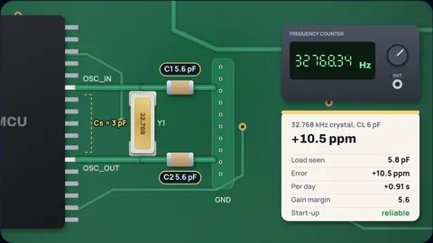
A 6 pF watch crystal
5.6 pF2 × (6 − 3) = 6 pF on each pin; the nearest E12 value is 5.6 pF, so the crystal sees 5.8 pF and runs 10.5 ppm fast, about 0.9 s a day.
At 51 ppm per pF this crystal is touchy: a picofarad of extra trace capacitance is a minute and a half a month.
A 7 pF watch crystal
8.2 pF2 × (7 − 3) = 8 pF, nearest E12 8.2 pF, −3.9 ppm. The gain margin with an STM32L4 LSE on medium-low drive is 4.3, under the 5 ST recommends, so a higher drive setting is safer.
A 12.5 pF crystal on a low-power oscillator
margin 1.5The capacitors are easy, 19 pF each, but gmcrit is 2.47 µA/V. Against 3.75 µA/V the gain margin is only 1.5, so this oscillator may not start reliably.
AN2867 says the STM32F0 and F3 high drive mode should be used only with 12.5 pF crystals, a sign of how much harder a high load is to drive. A lower ESR crystal or a 6 or 7 pF part brings the margin up.
22 pF caps on a 12.5 pF crystal
−18.5 ppm22 pF on each pin plus 3 pF of stray gives 14 pF, not 12.5. The crystal runs 18.5 ppm slow, 1.6 s a day or about 0.8 minutes a month.
8 MHz, 20 pF
27 pF2 × (20 − 5) = 30 pF. E12 has no 30 pF, so 27 pF gives 18.5 pF and +29.4 ppm with AN2867's example crystal. Switch to E24 for 30 pF.
16 MHz, 18 pF
27 pF2 × (18 − 5) = 26 pF; 27 pF gives 18.5 pF and −10.6 ppm. Gain margin 12 with a 25 mA/V oscillator.
25 MHz, 20 pF
margin 4.3gmcrit grows with the square of frequency. With the same 80 Ω and 7 pF example values, 25 MHz at 20 pF needs 5.76 mA/V and the margin falls to 4.3. Real 25 MHz crystals usually have lower ESR; check yours.
Unequal capacitors
21.4 pFIf C1 must be 33 pF, C2 = 1 ÷ (1 ÷ 13 − 1 ÷ 33) = 21.4 pF; the nearest E12 value, 22 pF, gives 18.2 pF.
Equal capacitors for common load capacitances
| Crystal CL | Cs 2 pF | Cs 3 pF | Cs 5 pF |
|---|---|---|---|
| 6 pF | 8 (8.2) | 6 (5.6) | 2 (1.8) |
| 7 pF | 10 (10) | 8 (8.2) | 4 (3.9) |
| 9 pF | 14 (15) | 12 (12) | 8 (8.2) |
| 12.5 pF | 21 (22) | 19 (18) | 15 (15) |
| 18 pF | 32 (33) | 30 (27) | 26 (27) |
| 20 pF | 36 (33) | 34 (33) | 30 (27) |
Exact value, with the nearest E12 capacitor in brackets, all in pF.
How the calculator works
Equal mode solves CL = C/2 + Cs for C; unequal mode solves the series formula for C2 given C1. Both round to the nearest E12 or E24 value and work out the load the crystal really sees.
The frequency error is the difference between the pulling at the real load and at the rated load, using AN2867's equation fL = fs(1 + Cm/(2(C0 + CL))).
gmcrit uses AN2867's formula with the rated CL. The gain margin is your oscillator's gm divided by gmcrit, and ST recommends at least 5.
What the model leaves out
- Measuring stray. Cs is an estimate. Measure the real frequency on a prototype and adjust.
- Drive level and series resistor. AN2867 also covers drive level and the external resistor; check them for small crystals.
- Tolerance and temperature. The crystal has its own tolerance and a temperature curve on top of the load error.
Common misconceptions
"The capacitors should equal CL." They act in series, so each is about twice CL less the stray.
"Bigger capacitors are more stable." They lower the frequency and raise gmcrit, making the oscillator harder to start.
"22 pF suits every crystal." On a 12.5 pF watch crystal it costs about 1.6 s a day.
Frequently asked questions
What is the formula for crystal load capacitors?
CL = C1 × C2 / (C1 + C2) + Cs. With equal capacitors, each is 2 × (CL − Cs).
What stray capacitance should I assume?
ST says experience puts it at 2 to 3 pF for STM32 boards; AN2867's worked example uses 5 pF. Measure the frequency on a prototype and adjust.
What happens if the load capacitors are wrong?
Too much capacitance makes the crystal run slow and harder to start, too little makes it run fast. 22 pF on a 12.5 pF watch crystal costs about 1.6 s a day.
What load capacitors does a 16 MHz 18 pF crystal need?
About 26 pF each with 5 pF of stray, or 30 pF with 3 pF of stray. 27 pF is the nearest E12 value.
What is gain margin for a crystal oscillator?
The oscillator's transconductance divided by gmcrit = 4 × ESR × (2πF)² × (C0 + CL)². ST recommends at least 5; AN2867's 8 MHz example reaches 64 with a 10 pF crystal.
Keep learning
32.768 kHz Crystal Not Starting or Running Slow? Fixes
Why a 32.768 kHz RTC crystal will not start, or loses seconds a day: gain margin, wrong load capacitors and stray, with ST AN2867's formulas.

How to Calculate Crystal Load Capacitors (With Stray C)
CL = C1·C2/(C1+C2) + Cstray, but which stray? Worked 18 pF example, the ppm error from getting it wrong, and the gain margin check most guides skip.
Why Watch Crystals Are 32,768 Hz (and Why Not Higher)
32,768 = 2^15, so 15 flip-flops give 1 Hz. The real reasons for 2^15 are fork size and oscillator power, and the parabolic temperature curve sets accuracy.