How do you calculate a buck converter?
Start with the duty cycle D = Vout ÷ (Vin × η), pick the inductor ripple (TI suggests 20 to 40 % of the load current), and the inductor is L = Vout(Vin − Vout) ÷ (ΔI × f × Vin). For 12 V to 5 V at 2 A and 500 kHz with 30 % ripple that is 9.72 µH, so a 10 µH part, with a peak current of 2.32 A.
For how the circuit works, read how a buck converter works. For choosing the inductor in detail, read how to choose the inductor for a buck converter.
The equations (TI SLVA477C)
- Duty cycle: D = Vout ÷ (Vin(max) × η), with η "e.g., estimated 90%".
- Inductor: L = Vout × (Vin − Vout) ÷ (ΔIL × fS × Vin), with ΔIL = 0.2 to 0.4 × Iout(max).
- Ripple and peak: ΔIL = (Vin − Vout) × D ÷ (fS × L); peak switch current = Iout + ΔIL ÷ 2.
- Output capacitor: C ≥ ΔIL ÷ (8 × fS × ΔVout), and the ESR adds ESR × ΔIL of ripple.
Seven buck designs
Each loads the schematic and the scope traces for the inductor current and the switch node.
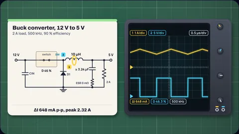
12 V to 5 V at 2 A, 500 kHz
10 µHD = 5 ÷ (12 × 0.9) = 0.463. With 30 % ripple, L = 5 × 7 ÷ (0.6 × 500 000 × 12) = 9.72 µH; 10 µH gives 648 mA of ripple and a 2.32 A peak.
For 50 mV of ripple the capacitance must be at least 3.24 µF, if the ESR is negligible.
The same at 20 % ripple
15 µHLess ripple needs more inductance: 15 µH instead of 10 µH, for 432 mA of ripple and a 2.22 A peak.
A 100 mΩ capacitor
ESR too highWith 100 mΩ of ESR the ripple current alone makes 65 mV, more than the 50 mV target. No amount of capacitance helps; the ESR must be under 77 mΩ.
24 V to 12 V at 2 A
22 µHD = 0.556. L works out at 20 µH, so 22 µH, with 606 mA of ripple and a 2.3 A peak.
5 V to 3.3 V at 1 A
6.8 µHA high duty cycle, 73 %. L = 7.48 µH, nearest 6.8 µH, ripple 367 mA.
LM2596, 12 V to 5 V at 3 A
3.37 A peakThe datasheet picks 33 µH for this case. At 150 kHz and the datasheet's 80 % efficiency, ΔI = 737 mA and the peak is 3.37 A. The 3.6 A minimum current limit leaves 3.23 A for the load, just enough.
The 0.1 Ω capacitor ESR alone makes 74 mV, within a 100 mV (2 %) target.
LM2596 at 0.3 A
discontinuousBelow half the ripple, 368 mA, the inductor current reaches zero each cycle and the converter goes discontinuous. The LM2596 datasheet puts this point at 0.31 A for its 2.5 A example.
Inductor for 30 % ripple, 12 V to 5 V at 2 A
| Frequency | Calculated L | Nearest E6 | Ripple |
|---|---|---|---|
| 150 kHz | 32.4 µH | 33 µH | 655 mA |
| 300 kHz | 16.2 µH | 15 µH | 720 mA |
| 500 kHz | 9.72 µH | 10 µH | 648 mA |
| 1 MHz | 4.86 µH | 4.7 µH | 690 mA |
| 2 MHz | 2.43 µH | 2.2 µH | 737 mA |
Ripple uses the duty cycle with 90 % efficiency, as in TI SLVA477C.
How the calculator works
Design mode solves SLVA477C equation 5 for L at your ripple ratio and rounds to the nearest E6 value. Check mode takes your inductor.
Ripple uses equation 2 with the duty cycle from equation 1; peak current is the load plus half the ripple. With a switch current limit, the most the converter can deliver is the limit minus half the ripple.
The capacitor solves ΔV = ΔI ÷ (8 f C) + ESR × ΔI for C. If the ESR term alone exceeds the target, no capacitance is enough.
What the model leaves out
- Discontinuous mode. Below half the ripple current the formulas change; the calculator flags it.
- Inductor saturation and losses. Check the inductor datasheet for saturation current and winding resistance.
- Loop compensation and load steps. Internally compensated parts such as the LM2596 want the inductor and capacitor ranges in their datasheet.
Common misconceptions
"A bigger inductor is always better." It lowers ripple but is larger, costs more and slows the response to load steps.
"Capacitance sets the ripple." With electrolytic capacitors the ESR term usually dominates.
"Peak current equals load current." The inductor and switch see the load plus half the ripple.
Frequently asked questions
What is the duty cycle of a buck converter?
D = Vout ÷ (Vin × η). TI includes the efficiency η because the converter must also supply its own losses; 90 % is a common estimate.
How do I choose the inductor value for a buck converter?
L = Vout(Vin − Vout) ÷ (ΔI × f × Vin), with ΔI 20 to 40 % of the load current. For 12 V to 5 V at 2 A and 150 kHz with 30 % ripple that is 32.4 µH, close to the 33 µH the LM2596 datasheet uses.
What is the peak inductor current?
The load current plus half the peak-to-peak ripple. The inductor must be rated above it without saturating.
How do I size the output capacitor?
C ≥ ΔI ÷ (8 × f × ΔV) for the capacitance, but the ESR adds ESR × ΔI. With electrolytics the ESR term is usually the larger.
What happens at light load?
When the load falls below half the ripple current, the inductor current reaches zero each cycle and the converter runs discontinuous. For the LM2596 at 33 µH that is about 368 mA.
Keep learning
How to Choose the Inductor for a Buck Converter
Pick a buck converter inductor in four steps: ripple ratio, inductance, peak current and saturation rating, with TI's equations and the LM2596 as a check.

How Does a Buck Converter Work? Worked 12 V to 3.3 V
How a buck converter works, from volt-second balance to Vout = D·Vin, with a worked 12 V to 3.3 V, 2 A design, computed waveforms and efficiency.
Does My 7805 Need a Heatsink? Work It Out in Two Lines
A 7805 needs a heatsink above about 1.5 W. Work out the power, the junction temperature and the heatsink you need from the datasheet numbers.