How to Choose the Inductor for a Buck Converter
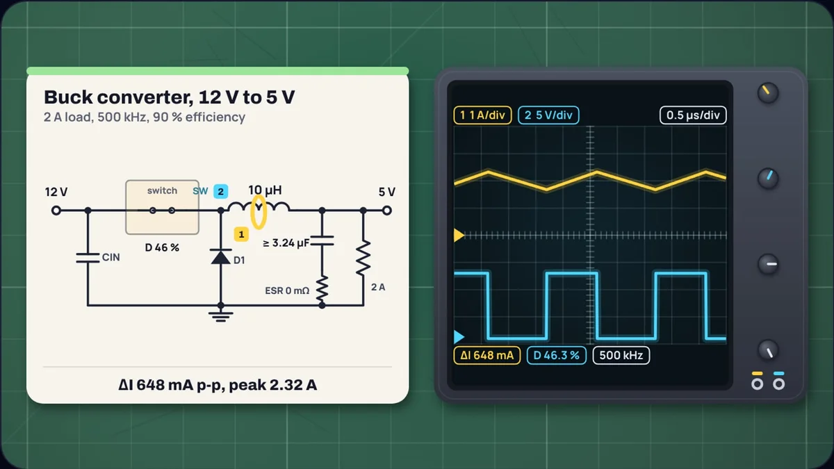
The inductor is the one part of a buck converter you cannot copy from the last design. Change the input voltage, the load or the switching frequency and the right value moves, sometimes by a factor of ten. A 12 V to 5 V converter at 500 kHz wants about 10 µH. The same conversion on an LM2596, which switches at 150 kHz, wants 33 µH. Both answers come from one formula and one choice: how much ripple current you are willing to let through.
This guide works through that choice and then the three checks that follow from it: the peak current, the saturation and current ratings, and the effect on the output capacitor. Our buck converter calculator runs every step and draws the inductor current on a scope. If you want to know why a buck converter works at all, start with how a buck converter works, which derives Vout = D × Vin and sizes a 12 V to 3.3 V design.
What does the inductor actually do?
The switch connects the inductor to the input for a fraction D of each cycle and to ground (through the diode or the low-side switch) for the rest. While the switch is on, the inductor sees Vin − Vout and its current ramps up. While it is off, it sees −Vout and the current ramps down. The result is a triangle wave riding on the load current. The height of that triangle, peak to peak, is the ripple current ΔI.
The inductance sets the slope. A bigger inductor ramps more slowly, so the triangle is smaller. That is the whole trade: inductance against ripple. Everything else in this guide is a consequence of where you set it.
Step 1: choose the ripple ratio
TI's application note SLVA477, "Basic Calculation of a Buck Converter's Power Stage", gives a starting point: "A good estimation for the inductor ripple current is 20% to 40% of the output current." Most designs land near the middle, 30 %.
Why not less? Less ripple needs more inductance, and more inductance means more turns of wire or a bigger core. The note adds that "the lower the inductor value, the smaller is the solution size". A large inductor also slows the converter's response, because the current can only change as fast as the inductor allows.
Why not more? Every bit of ripple adds to the peak current the switch and inductor must carry, adds to the output voltage ripple, and raises the load at which the converter goes discontinuous. More on all three below.
Step 2: calculate the inductance
With the ripple chosen, SLVA477's equation 5 gives the inductance:
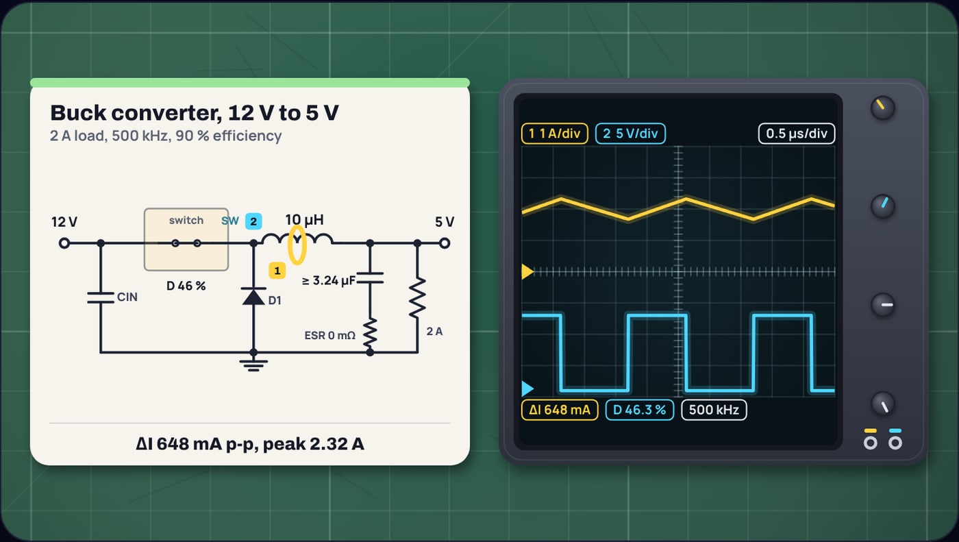
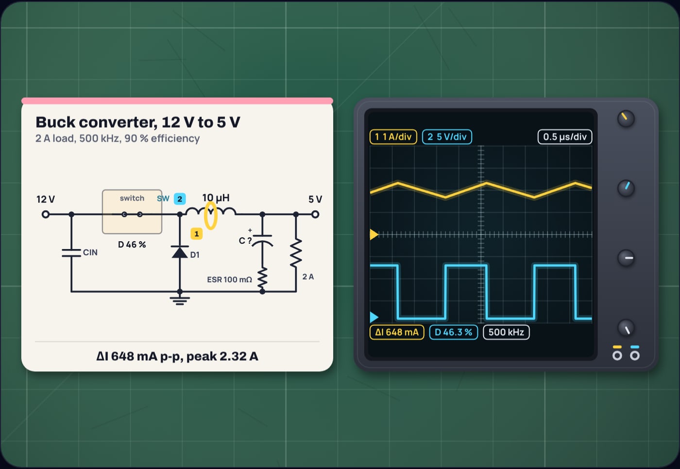
For 12 V to 5 V at 2 A, 500 kHz, with 30 % ripple (ΔI = 0.6 A):
Inductors come in standard values, mostly from the E6 series: 1, 1.5, 2.2, 3.3, 4.7 and 6.8 in each decade. The nearest is 10 µH. Use the input voltage at which the ripple is largest, which for a buck converter is the highest input you expect, since the formula grows with Vin.
Step 3: recalculate the ripple and the peak current
Now go back the other way with the inductor you will actually fit. SLVA477 does this with a duty cycle that includes the efficiency, because the converter has to deliver its own losses too:
The note suggests an estimated 90 % efficiency if you have nothing better. Then the peak current is the load plus half the ripple:
The ripple came out at 32 % rather than 30 %. Part of that is the rounding from 9.72 to 10 µH, and part is the efficiency term: equation 5 uses the ideal duty cycle, equation 2 the longer one. The difference is small and on the safe side, since you then rate the parts for the larger number.
Here is how the ripple ratio changes the answer for the same converter:
| Ripple ratio | Calculated L | Fitted L | Ripple | Peak current |
|---|---|---|---|---|
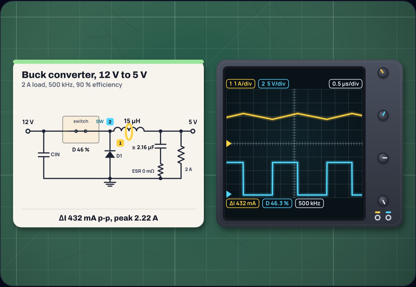
| 20 % | 14.6 µH | 15 µH | 432 mA | 2.22 A |
| 30 % | 9.72 µH | 10 µH | 648 mA | 2.32 A |
| 40 % | 7.29 µH | 6.8 µH | 953 mA | 2.48 A |
Going from 20 % to 40 % halves the inductance but adds only a quarter of an amp to the peak. That is why designs that care about size lean toward the top of the range.
Step 4: read the inductor datasheet
An inductor datasheet gives two current ratings, and you need both.
- Saturation current. Above it the core cannot store more energy and the inductance drops. The LM2596 datasheet describes what follows: "the inductance decreases rapidly and the inductor begins to look mainly resistive", the switch current rises very fast and the regulator goes into cycle-by-cycle current limit. The saturation rating must be above the peak current, with margin for the highest input voltage and for start-up.
- RMS or heating current. This is about copper loss. For a triangle of height ΔI on a load current I, the RMS value is √(I² + ΔI²/12). For 2 A and 0.648 A of ripple that is 2.009 A, barely more than the load. In continuous mode the heating rating is set by the load current.
SLVA477 puts it simply: the inductor "must always have a higher current rating than the maximum current given in Equation 4", the peak switch current. The LM2596 datasheet adds a practical point about construction: open bobbin or rod cores are cheapest but let flux escape, which can couple into nearby traces and scope probes. Where several converters share a board it calls for a toroid or E-core, which keep the flux inside.
Does the switch current limit agree?
The switch inside the regulator has a current limit too, and it has to cover the peak. SLVA477's equation 3 gives the most output current a part can supply: its minimum current limit minus half the ripple.
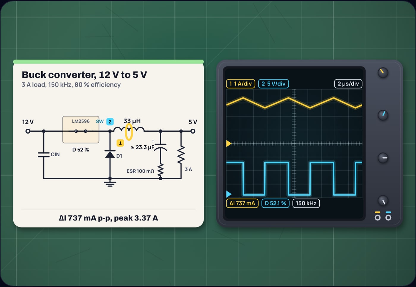
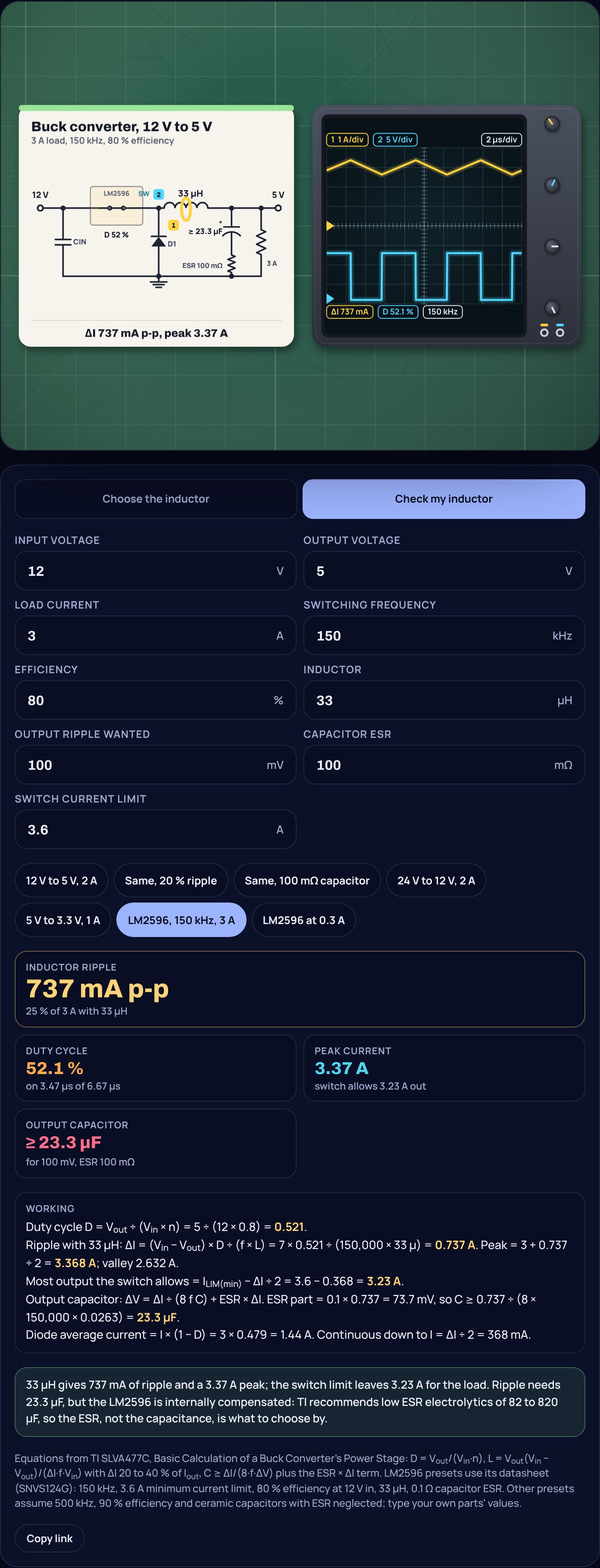
The LM2596 is a good test case. TI's datasheet gives a 150 kHz oscillator, a current limit of 3.6 A minimum at 25 °C (3.4 A over temperature) and 80 % efficiency for the 5 V version at 12 V in and 3 A. Its own design example takes 12 V to 5 V at 3 A and picks 33 µH. Run that through the equations:
That clears the 3 A load at 25 °C. Over temperature, with 3.4 A, it is 3.03 A: enough, but only just. A smaller inductor would push the peak past the limit and the regulator would cap the output below 3 A.
The datasheet also works a 2.5 A example from 12 V with 33 µH, reading about 620 mA of ripple off its graph, a 2.81 A peak and 62 mV of output ripple with a 0.1 Ω capacitor. With SLVA477's suggested 90 % efficiency the formula gives 655 mA and 2.83 A, within a few percent of the graph.
Why does switching frequency change the answer so much?
Frequency sits in the denominator. Double it and the inductor halves for the same ripple. For 12 V to 5 V at 2 A with 30 % ripple:
| Frequency | Calculated L | Nearest E6 |
|---|---|---|
| 150 kHz | 32.4 µH | 33 µH |
| 300 kHz | 16.2 µH | 15 µH |
| 500 kHz | 9.72 µH | 10 µH |
| 1 MHz | 4.86 µH | 4.7 µH |
| 2 MHz | 2.43 µH | 2.2 µH |
The 150 kHz row lands on 33 µH, the same value the LM2596 datasheet chooses. That is why a 150 kHz converter needs a physically larger inductor than one running at a megahertz or more. Higher frequency has its own cost, chiefly switching losses in the transistor, so this is a trade.
What happens at light load?
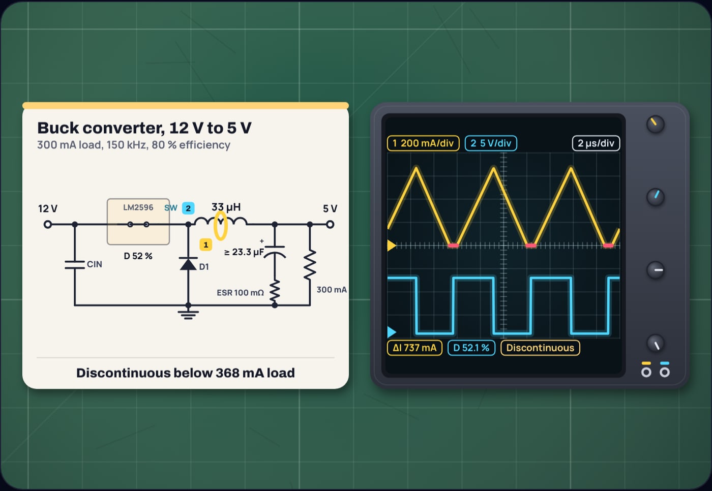
The triangle's lowest point is the load current minus half the ripple. When the load falls below ΔI ÷ 2, that lowest point would be negative. A diode cannot conduct backwards, so instead the current reaches zero and stays there for part of each cycle. The converter is now in discontinuous conduction mode, and the formulas above stop applying.
For the LM2596 with 33 µH, that happens below about 0.37 A in the 3 A design; the datasheet's own 2.5 A example puts it at 0.31 A. Discontinuous mode is not a fault, but the output ripple, the duty cycle and the loop behaviour all change. If the converter has to stay continuous down to a lighter load, the only fix is a larger inductor.
How does the inductor choice affect the output capacitor?
All the ripple current flows into the output capacitor. SLVA477 gives the minimum capacitance for a ripple target, and adds a second term for the capacitor's equivalent series resistance:
The LM2596 datasheet says the allowable ripple is "typically 1% to 2% of the output voltage". At 1 % of 5 V, 50 mV, our 500 kHz design with 0.648 A of ripple needs only 3.24 µF if the ESR is negligible, as with ceramic capacitors. Put a 100 mΩ capacitor there instead, the ESR the LM2596 datasheet uses in its example, and the ESR term alone is 0.1 × 0.648 = 65 mV, past the target before the capacitance even counts. The ESR must be below 50 ÷ 0.648 = 77 mΩ.
The calculator adds the two terms, which is the cautious choice. The buck converter explainer shows why the real total is a little lower: the two ripples peak at different moments in the cycle. Either way, the lesson for the inductor is the same. Every extra milliamp of ripple you allow is paid for at the output, and with electrolytic capacitors it is paid through the ESR.
One caution for regulators with internal compensation, such as the LM2596: SLVA477 says to use the recommended inductor and capacitor values, or follow the datasheet's rules for adjusting them. The LM2596 asks for low ESR electrolytics between 82 µF and 820 µF, or solid tantalum between 10 µF and 470 µF, whatever the ripple sum says.
A checklist for your own converter
- Take the highest input voltage, the output voltage, the largest load and the lowest switching frequency.
- Choose a ripple ratio, 30 % unless you have a reason not to, and calculate L. Round to a standard value.
- Recalculate the ripple with the efficiency in the duty cycle, then the peak current.
- Check the regulator's minimum current limit minus half the ripple covers the load.
- Buy an inductor whose saturation current is above the peak and whose heating rating covers the load.
- Note the load below which the converter goes discontinuous, and size the output capacitor and its ESR for the ripple.
The buck converter calculator does each of these in order and shows the working. If you are deciding between a switcher and a linear regulator in the first place, does my 7805 need a heatsink? shows how quickly a linear part runs out of thermal room.
Sources
- Texas Instruments, SLVA477C, Basic Calculation of a Buck Converter's Power Stage, December 2011, revised September 2026 (duty cycle with efficiency, ripple current, maximum output current from the switch limit, peak switch current, inductor equation, ripple of 20 to 40 %, output capacitance and ESR ripple, use of recommended values for internally compensated parts): ti.com SLVA477
- Texas Instruments, LM2596 SIMPLE SWITCHER Power Converter 150-kHz 3-A Step-Down Voltage Regulator, SNVS124G, November 1999, revised March 2023 (150 kHz oscillator, 3.6 A and 3.4 A minimum current limit, 80 % efficiency for the 5 V version, 33 µH design example, 2.5 A ripple example, saturation behaviour, core construction, ripple of 1 to 2 %, capacitor ranges): ti.com LM2596
Frequently asked questions
How do I calculate the inductor for a buck converter?
Use L = Vout × (Vin − Vout) ÷ (ΔI × f × Vin), where ΔI is the ripple current you allow, usually 20 to 40 % of the load current. For 12 V to 5 V at 2 A and 500 kHz with 30 % ripple, L = 9.72 µH, so a 10 µH part.
What ripple current should I choose for a buck inductor?
TI’s application note SLVA477 calls 20 to 40 % of the maximum output current a good estimate. Less ripple needs a larger inductor; more ripple raises the peak current, the output ripple and the load at which the converter goes discontinuous.
What current rating does the inductor need?
At least the peak current, the load plus half the ripple, without saturating. For 12 V to 5 V at 2 A with 10 µH at 500 kHz that is 2.32 A. Its heating depends on the RMS current, which for a small ripple is very close to the load current.
What happens if the inductor value is too small?
The ripple grows in inverse proportion to the inductance. The peak current rises, which can hit the switch current limit, the output ripple rises, and the converter goes discontinuous at a higher load.
Why does the LM2596 use 33 µH?
It switches at 150 kHz, so it needs more inductance than a faster converter for the same ripple. For 12 V to 5 V at 2 A with 30 % ripple, TI’s formula gives 32.4 µH at 150 kHz, and the LM2596 datasheet picks 33 µH for its 12 V to 5 V, 3 A example.