5V to 3.3V With a Voltage Divider (and When Not To)
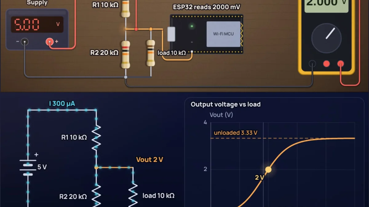
Your 5 V Arduino sends serial data at 5 V. Your ESP32 runs at 3.3 V, and Espressif does not rate its pins for 5 V. The fix that costs one rupee is two resistors: 10 kΩ in series and 20 kΩ to ground turn 5 V into 3.33 V. That trick is right for this job and wrong for several jobs that look almost the same, and the difference comes down to one question: how much current does the thing on the output draw?
This post works through the values, the standard resistor pairs, the speed limit and the cases where a divider fails. Every number can be checked in the voltage divider calculator, which shows the output sagging as you add a load.
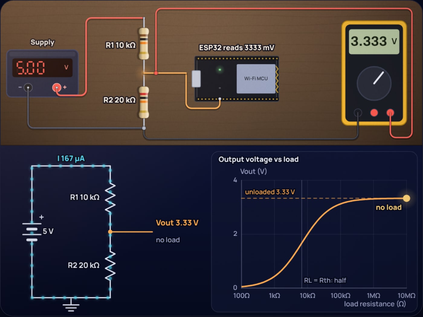
How does a voltage divider step 5V down to 3.3V?
Two resistors in series carry the same current, so each one takes a share of the voltage in proportion to its resistance. The output is the share across the bottom resistor:
For 3.3 V out of 5 V the ratio is 3.3 ÷ 5 = 0.66, so R2 should be about twice R1. That ratio is all the formula cares about. The size of the resistors decides two other things: how much current the divider wastes, and how much it is disturbed by whatever you connect to it.
.
Current through both resistors: .
Power turned into heat: , nothing a resistor will notice.
Which resistor values should you use?
Any pair with R2 close to 2 × R1 gives roughly 3.3 V. Here are pairs you can buy from the E12 and E24 series, all on a 5 V input:
| R1 (top) | R2 (bottom) | Vout | Current wasted | Source resistance |
|---|---|---|---|---|
| 1 kΩ | 2 kΩ | 3.333 V | 1,667 µA | 667 Ω |
| 1.8 kΩ | 3.3 kΩ | 3.235 V | 980 µA | 1.17 kΩ |
| 2.2 kΩ | 3.9 kΩ | 3.197 V | 820 µA | 1.41 kΩ |
| 4.7 kΩ | 9.1 kΩ | 3.297 V | 362 µA | 3.10 kΩ |
| 5.1 kΩ | 10 kΩ | 3.311 V | 331 µA | 3.38 kΩ |
| 10 kΩ | 20 kΩ | 3.333 V | 167 µA | 6.67 kΩ |
| 22 kΩ | 43 kΩ | 3.308 V | 77 µA | 14.6 kΩ |
The last column is the one most tutorials skip. Seen from its output, a divider behaves like a 3.33 V source with a resistor in series equal to R1 and R2 in parallel, . That resistance decides how the output reacts to a load and how fast it can change.
For a plain GPIO input, 10 kΩ and 20 kΩ is a sensible default. If you only have E12 values, 1.8 kΩ and 3.3 kΩ gives 3.24 V, which every 3.3 V chip reads as a clear HIGH. Avoid going much above 50 kΩ in total for logic signals, for the speed reason below.
What happens when you connect a load?
Whatever is connected to the output sits in parallel with R2. A logic input draws well under a microamp, so it changes nothing. Anything that draws real current lowers the bottom resistance and drags the output down.
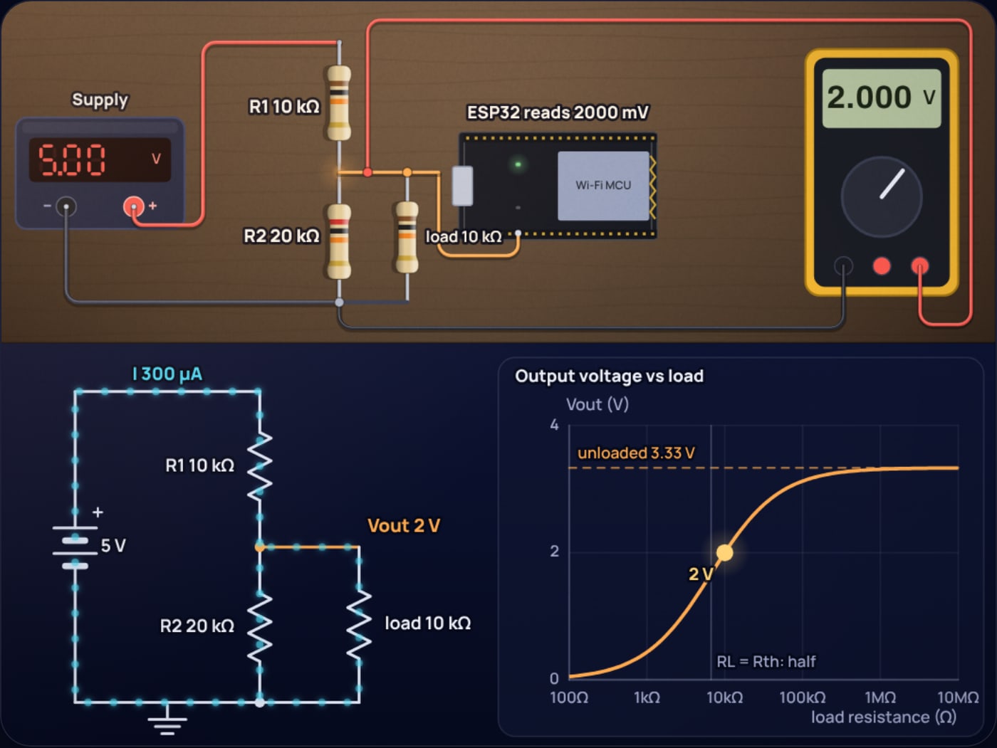
Bottom of the divider: .
, a 40% drop.
Same answer the quick way: , the Thevenin source driving the load through 6.67 kΩ.
The rule that falls out of this: to keep the error under 1%, the load must be at least 99 times the source resistance. For 10 kΩ and 20 kΩ that means 660 kΩ or more. A microcontroller input easily qualifies. A sensor module, an LED or a radio does not.
Can you power a 3.3V module from a voltage divider?
No, and this is the most common misuse. A 3.3 V module that draws 10 mA looks like a 330 Ω load.
Shrinking the resistors until they can supply 10 mA means hundreds of milliamps flowing through the divider all the time, and the output still moves every time the module's current changes, which for a Wi-Fi radio is constantly. Power needs a regulator. A 3.3 V LDO costs a few rupees and holds its output steady from no load to its rated current. The longer argument, with the numbers for different loads, is in can you use a voltage divider as a power supply.
Is a voltage divider fast enough for UART, SPI and I2C?
Every input pin has some capacitance, from the pin itself and the wiring. The divider's source resistance charges that capacitance, which makes a low-pass filter. Assume about 10 pF in total.
So a 10 kΩ and 20 kΩ divider is fine for UART, button signals, interrupt lines and slow chip selects. For SPI at a few megahertz, either scale the resistors down (1 kΩ and 2 kΩ cut the edge to about 15 ns, at 1.7 mA of standing current) or use a buffer. I2C is a different problem: its lines are bidirectional and open-drain, and a divider only works in one direction, so use the MOSFET shifter described in the 3.3 V to 5 V level shifter post.
Reading a battery or sensor through a divider
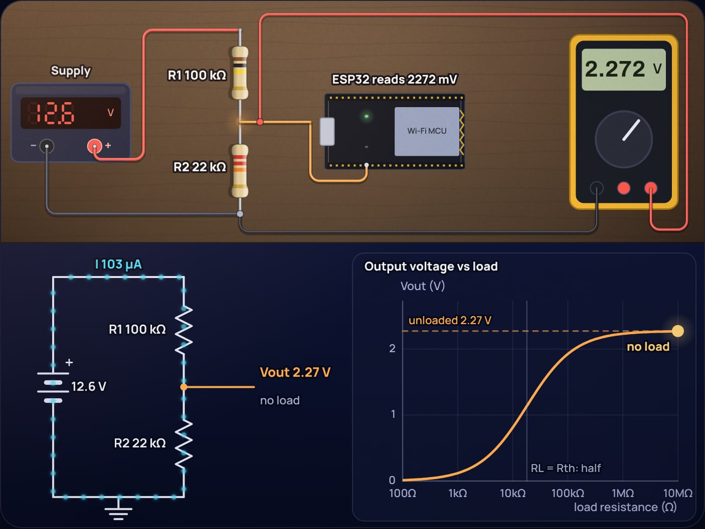
The other big use of dividers is bringing a voltage that is too high into an ADC pin. A 12.6 V battery through 20 kΩ over 10 kΩ gives 4.2 V at an Arduino's A0, which analogRead reports as 860 of 1023.
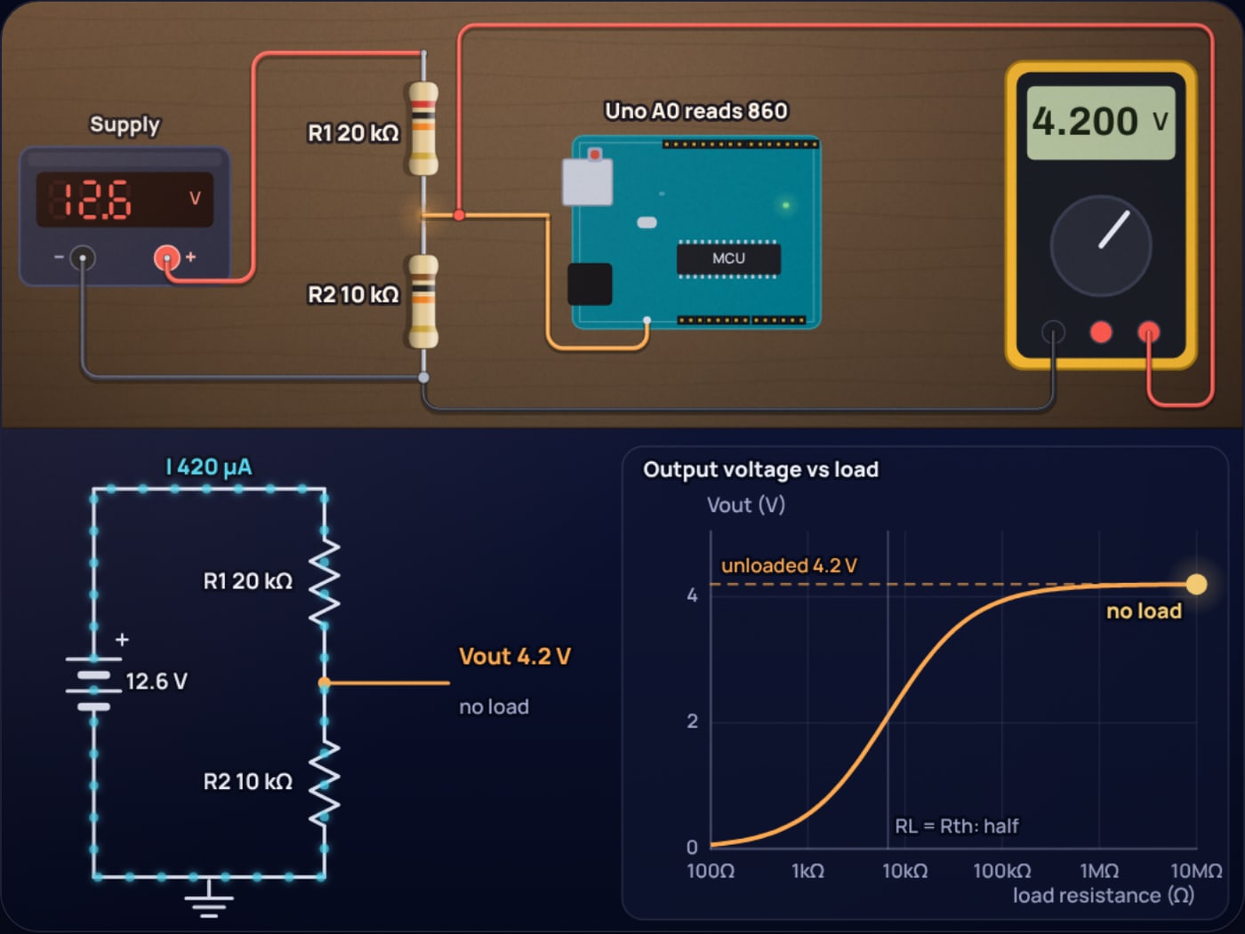
Two limits matter here. The ATmega328P ADC is designed for sources of about 10 kΩ or less, because each reading briefly charges a small sampling capacitor. And the ESP32 ADC is most accurate between 150 mV and 2450 mV at its 11 dB setting, so for an ESP32 divide further: 100 kΩ over 22 kΩ turns 12.6 V into 2.27 V. With resistors that large, add a 100 nF capacitor from the pin to ground so the ADC samples a steady voltage. The ADC resolution and accuracy post explains how much of the reading you can trust.
How accurate is a resistor divider?
Resistor tolerance moves the ratio. With two 5% resistors the worst case for 10 kΩ over 20 kΩ is R1 at 9.5 kΩ and R2 at 21 kΩ, which gives 3.44 V, or R1 at 10.5 kΩ and R2 at 19 kΩ, which gives 3.22 V. For a logic signal nobody cares. For a battery gauge that is the difference between "half full" and "nearly empty", so use 1% resistors and calibrate once against a multimeter.
When should you not use a voltage divider?
- To power anything. Use a regulator.
- To go from 3.3 V up to 5 V. A divider only divides. Many 5 V inputs already read 3.3 V as HIGH; otherwise use a 74HCT buffer or a level shifter.
- On bidirectional lines. I2C and one-wire buses need a proper bidirectional shifter.
- For fast signals. Above a few megahertz the edges smear. Use a buffer.
- Where standby current matters and accuracy does too. Large resistors save current but upset the ADC. Use a capacitor at the pin, or switch the divider off with a MOSFET between readings.
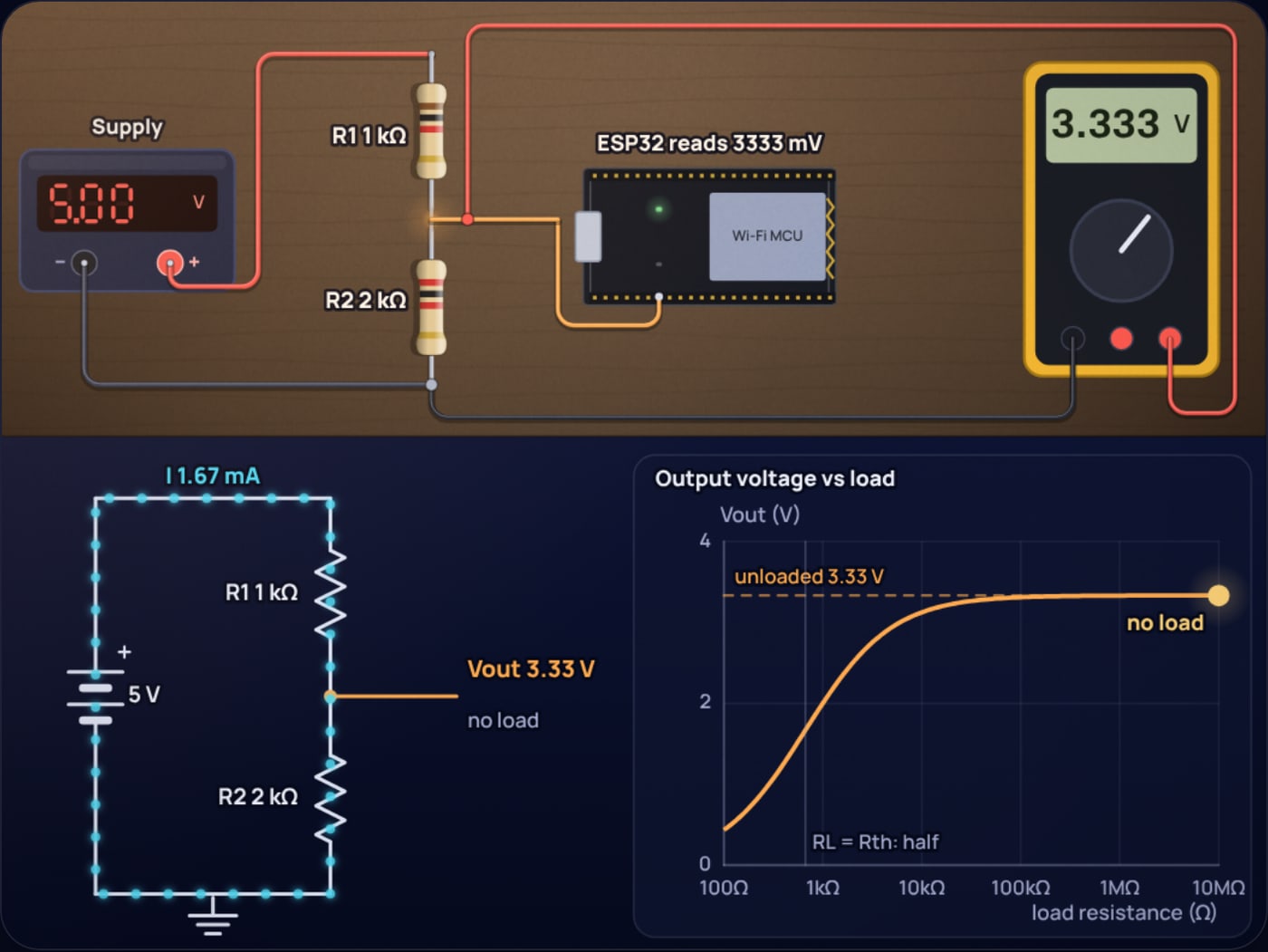
To get a feel for the trade-off, open the loaded divider in the simulator, then slide R1 and R2 down together. The output under load climbs back toward 3.33 V while the current wasted climbs with it. Somewhere in between is the right pair for your circuit.
Sources
- Microchip ATmega328P ADC single-ended conversion result: ADC = VIN × 1024 / VREF.
- Nuts and Volts, Analog front ends (February 2016): quotes the AVR ADC design limit of about 10 kΩ source impedance.
- Espressif ESP-IDF v4.4 ADC documentation for the ESP32: measurable input range 150 mV to 2450 mV at 11 dB attenuation.
- Espressif ESP-IDF ADC oneshot driver: raw to voltage conversion and calibration.
Frequently asked questions
What resistors convert 5V to 3.3V?
Use a bottom resistor twice the top one. 10 kilohms on top and 20 kilohms to ground give 3.33 V and draw 167 microamps. The closest standard E24 pair to exactly 3.3 V is 4.7 kilohms over 9.1 kilohms, which gives 3.297 V. 1 kilohm and 2 kilohms also work but waste ten times more current.
Can I power a 3.3V module from 5V with a voltage divider?
No. The output of a divider falls as soon as current is drawn from it. A module drawing 10 mA from a 10 kilohm and 20 kilohm divider would pull the output down to about 0.16 V. Use a 3.3 V regulator such as an LDO for power, and keep dividers for signals.
Is a voltage divider fast enough for UART or SPI?
For UART at common baud rates, yes. With 10 kilohms and 20 kilohms and about 10 pF of input capacitance, the edge takes roughly 150 ns, under 2 percent of a 115200 baud bit. For SPI at several megahertz, or I2C, use a level shifter chip or smaller resistors.
Can a voltage divider convert 3.3V up to 5V?
No. A divider can only reduce a voltage. To send a 3.3 V signal into a 5 V input, check whether the 5 V input already accepts 3.3 V as HIGH, use a 74HCT buffer, or use a level shifter.
Why does my divider give a lower voltage than calculated?
Usually because something is loading the output, or the resistors are off by their tolerance. A load in parallel with the bottom resistor lowers the output, and two 5 percent resistors can move a 3.33 V output anywhere from about 3.22 V to 3.44 V. Measure the resistors, use 1 percent parts, and keep the load more than 100 times the divider’s source resistance.
 555 Timer Frequency Formula: Where 1.44 Comes From
 ADC Resolution vs Accuracy: ENOB, INL and the Reference
