How does a voltage divider work?
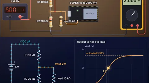
Two resistors in series share the input voltage in proportion to their resistance, so the voltage across the bottom one is Vin × R2 ÷ (R1 + R2). With 5 V, R1 = 10 kΩ and R2 = 20 kΩ the output is 3.33 V, and the pair draws 167 µA all the time. That holds only while nothing draws current from the output: connect a 10 kΩ load and it falls to 2 V.
Most voltage divider calculators stop at the first formula. This one adds the load, the ADC reading and the current wasted, because those three decide whether a divider works in a real circuit. It is excellent for reading a battery voltage or shifting a slow signal down to 3.3 V, and a poor way to power anything, as the post can you use a voltage divider as a power supply explains.
Key results from the simulation
- 5 V to 3.3 V: 10 kΩ over 20 kΩ gives 3.33 V. The closest E24 pair to exactly 3.3 V is 4.7 kΩ over 9.1 kΩ, giving 3.3 V.
- Loading pulls the output down: a 10 kΩ load on that divider drops it to 2 V, a 40% sag. To stay within 1% the load must be at least 660 kΩ, which is 99 times the divider's 6.67 kΩ source resistance.
- Current wasted: 10 kΩ and 20 kΩ on 5 V waste 167 µA (833 µW). 1 kΩ and 2 kΩ give the same ratio and waste 1.67 mA.
- Battery monitor on an Uno: 12.6 V through 20 kΩ over 10 kΩ gives 4.2 V, which analogRead reports as 860 of 1023.
- High resistances and the ADC: 1 MΩ over 330 kΩ wastes only 9.47 µA, but its 248 kΩ source resistance is far above the 10 kΩ the ATmega328P ADC is designed for.
Six dividers worth trying
Each section loads a setup into the calculator. The numbers below are the ones the simulation shows.
Step 5 V down to 3.3 V
10 kΩ over 20 kΩA 5 V sensor or Arduino output sending a signal into a 3.3 V ESP32 pin is the classic job for a divider. R2 should be twice R1, so 10 kΩ and 20 kΩ give 3.33 V. The ESP32 input draws almost nothing, so the output stays where the formula puts it.
This works for slow signals and serial lines at moderate baud rates. For fast or two-way signals such as I2C, use a proper level shifter instead, see the 3.3 V to 5 V level shifter post.
Connect a 10 kΩ load and watch it sag
Same divider, loadedConnect a 10 kΩ load across R2 and the bottom of the divider becomes 20 kΩ in parallel with 10 kΩ, which is 6.67 kΩ. The output becomes 5 × 6.67 kΩ ÷ (10 kΩ + 6.67 kΩ) = 2 V, a 40% drop from 3.33 V.
The quick way to predict this is the Thevenin view: the divider behaves like a 3.33 V source with 6.67 kΩ in series (R1 in parallel with R2). A load equal to that resistance halves the output, which is the marked point on the curve.
Read a 12 V battery with an Arduino Uno
20 kΩ over 10 kΩA charged 12 V lead-acid battery sits near 12.6 V, too much for a 5 V analog pin. Dividing by three with 20 kΩ over 10 kΩ gives 4.2 V, and the Uno reads 860 of 1023, each step worth 4.88 mV at the pin or 14.6 mV at the battery.
The divider takes 420 µA from the battery continuously, about 10 mAh a day. For a battery left for months, use larger resistors with a capacitor on the pin, or switch the divider off between readings. The ADC resolution post explains why the last digit is less certain than it looks.
Read the same battery with an ESP32
100 kΩ over 22 kΩThe ESP32 ADC is most accurate between 150 mV and 2450 mV at its 11 dB setting, so aim a little lower. 100 kΩ over 22 kΩ turns 12.6 V into 2.27 V, inside that window, and draws only 103 µA.
Read it with analogReadMilliVolts rather than the raw count, because the ESP32 ADC is not linear near its ends and each chip carries a factory calibration.
Small resistors: stiff output, wasted power
1 kΩ over 2 kΩSame ratio as the first setup, ten times smaller resistors. The output is still 3.33 V but the divider now burns 1.67 mA and 8.33 mW for nothing.
In return it is ten times stiffer: the same 10 kΩ load now only pulls it to 3.13 V, a 6.3% sag instead of 40%. That is the whole trade-off of a divider: low resistance for a stiff output, high resistance for low waste.
Huge resistors and the ADC
1 MΩ over 330 kΩTo save battery you might pick 1 MΩ over 330 kΩ: 3.13 V out of 12.6 V for only 9.47 µA. The divider looks perfect on paper, but its source resistance is 248 kΩ.
The ATmega328P ADC charges a small sampling capacitor for each reading and is designed for sources of about 10 kΩ or less. Through 248 kΩ the capacitor does not fully charge, and readings drift, especially after reading another channel. The usual fix is a 100 nF capacitor from the pin to ground, which holds the voltage steady while the ADC samples it.
Every setup at a glance
| Setup | Vin | R1 / R2 | Vout | Current wasted | Source resistance |
|---|---|---|---|---|---|
| 5 V to 3.3 V | 5 V | 10 kΩ / 20 kΩ | 3.33 V | 167 µA | 6.67 kΩ |
| Same, 10 kΩ load | 5 V | 10 kΩ / 20 kΩ | 2 V | 300 µA | 6.67 kΩ |
| Battery on Uno | 12.6 V | 20 kΩ / 10 kΩ | 4.2 V | 420 µA | 6.67 kΩ |
| Battery on ESP32 | 12.6 V | 100 kΩ / 22 kΩ | 2.27 V | 103 µA | 18 kΩ |
| Small resistors | 5 V | 1 kΩ / 2 kΩ | 3.33 V | 1.67 mA | 667 Ω |
| Huge resistors | 12.6 V | 1 MΩ / 330 kΩ | 3.13 V | 9.47 µA | 248 kΩ |
Current wasted is the current drawn from the input. With a load connected, part of it flows into the load. Source resistance is R1 in parallel with R2, the Thevenin resistance of the output.
How the simulation works
Unloaded, the same current Vin ÷ (R1 + R2) flows through both resistors, so the output is Vin × R2 ÷ (R1 + R2). With a load RL the bottom of the divider becomes R2 in parallel with RL, R2 × RL ÷ (R2 + RL), and the same formula applies with that value in place of R2.
The curve on the chart is the output for every load from 100 Ω to 10 MΩ. The dashed line is the unloaded value. The vertical line marks a load equal to R1 ∥ R2, where the output is exactly half the unloaded value. A load of 99 times that resistance costs 1%.
The Uno reading uses the ATmega328P formula ADC = Vin × 1024 ÷ Vref with a 5 V reference, rounded down and capped at 1023. For the ESP32 the calculator shows the voltage in millivolts, which is what analogReadMilliVolts returns after calibration, and warns outside the 150 to 2450 mV range Espressif gives for 11 dB attenuation. The E24 finder searches every pair of standard values with a total between 10 kΩ and 200 kΩ for the ratio closest to the current one.
What the model leaves out
- Resistor tolerance: two 5% resistors can shift the ratio by several percent (up to about 7% for a divide-by-three). Use 1% parts for battery monitoring, or calibrate in software.
- The real ADC input: an ADC sample is a brief current pulse into a capacitor. The model treats the ADC as an open circuit and only warns about high source resistance.
- Reference accuracy: the Uno reading assumes exactly 5.00 V on the reference. USB power is often a little above or below 5 V, which shifts every reading by the same percentage.
- Temperature and voltage coefficients: resistor values drift slightly with heat. At the tiny powers here it does not matter.
- Frequency: with fast signals, pin capacitance and the divider resistance form a low-pass filter that rounds the edges. The model is DC only.
Common misconceptions
“A voltage divider is a cheap voltage regulator.” Only with no load. The moment the load draws current the output falls, and it moves again every time the load current changes. Use a regulator to power things.
“Bigger resistors are always better because they waste less.” Too big and the divider can no longer drive even an ADC input properly. Aim for a source resistance below 10 kΩ for an Arduino, or add a capacitor at the pin.
“The output depends on the resistor values.” It depends on their ratio. 1 kΩ over 2 kΩ and 100 kΩ over 200 kΩ give the same unloaded output; they differ in waste and stiffness.
Frequently asked questions
What is the voltage divider formula?
Vout = Vin × R2 ÷ (R1 + R2), where R1 is the resistor connected to the input and R2 the one connected to ground. With a load RL on the output, replace R2 with R2 × RL ÷ (R2 + RL).
What resistors do I need to get 3.3 V from 5 V?
R2 should be twice R1. 10 kΩ and 20 kΩ give 3.33 V, and 1 kΩ and 2 kΩ give the same voltage but waste ten times more current. The closest E24 pair to exactly 3.3 V is 4.7 kΩ over 9.1 kΩ, giving 3.3 V.
Why does the output voltage drop when I connect a load?
Because the load is in parallel with R2, lowering the bottom resistance. For 10 kΩ over 20 kΩ on 5 V, a 10 kΩ load drops the output from 3.33 V to 2 V. Keep the load at least 100 times the divider's source resistance (R1 in parallel with R2) for less than 1% error.
How do I measure a 12 V battery with an Arduino?
Divide it down below 5 V. With 20 kΩ on top and 10 kΩ on the bottom, 12.6 V becomes 4.2 V and analogRead returns 860. Multiply the reading by 5 ÷ 1024 and then by 3 to get the battery voltage back. Use 1% resistors for accuracy.
How much current does a voltage divider waste?
Vin ÷ (R1 + R2), all the time. 10 kΩ plus 20 kΩ on 5 V wastes 167 µA, which is 833 µW. 1 kΩ plus 2 kΩ wastes 1.67 mA. On a battery-powered project choose the largest values your ADC can tolerate.
Keep learning
5V to 3.3V With a Voltage Divider (and When Not To)
Step a 5 V signal down to 3.3 V with two resistors: which values to use, the E24 pairs, how loading and pin speed limit it, and when you need a regulator.

Can You Use a Voltage Divider as a Power Supply?
A 7 kΩ / 5 kΩ divider makes 5 V from 12 V until you load it: at 20 mA it gives 0.39 V. The Thevenin math, the efficiency limit, and when a divider is fine.

3.3V to 5V Level Shifter: When You Need One and Why
When a 3.3 V output already reads as HIGH at 5 V, how the BSS138 shifter works, why its 10k pull-ups fail 400 kHz I2C, and when two resistors are enough.

ADC Resolution vs Accuracy: ENOB, INL and the Reference
A 10-bit Arduino ADC resolves 4.9 mV but can be 130 mV wrong. Resolution vs accuracy, ENOB = (SINAD − 1.76)/6.02, INL/DNL, and what averaging fixes.