Electric Field Lines: Rules and Diagrams for Every Case
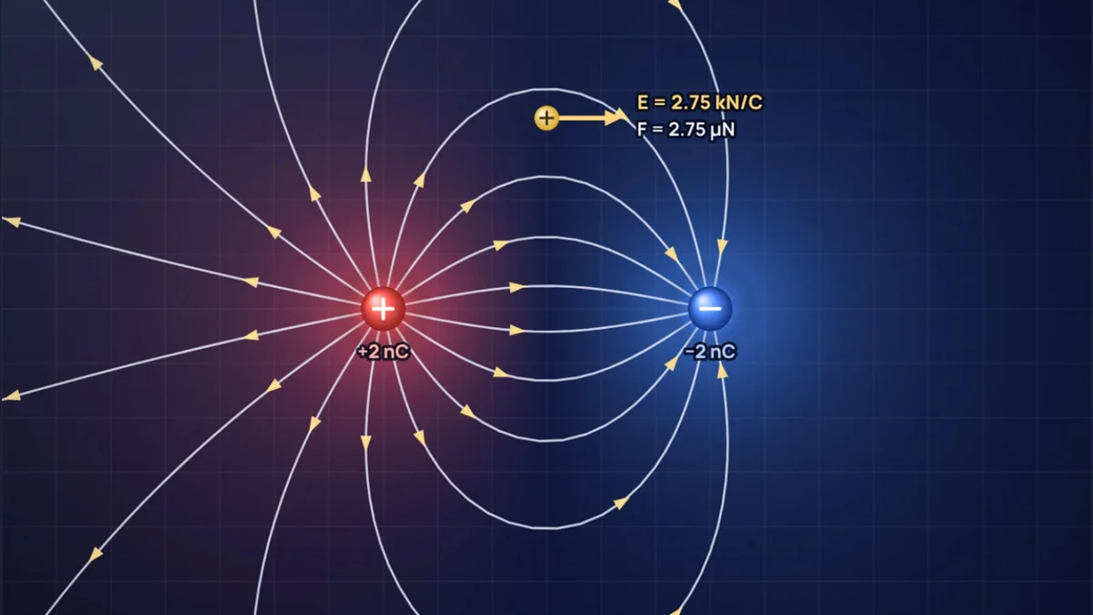
An electric field is invisible, so physicists draw it. A field line is a curve whose direction at every point is the direction a small positive charge would be pushed. Draw enough of them by a few simple rules and the picture tells you the direction of the force everywhere, roughly how strong it is, and where it vanishes. This guide goes through those rules and then applies them to every arrangement that comes up in Class 12 and first year physics. Every diagram here was drawn by our electric field lines simulator, which traces the lines from Coulomb's law and lets you drag the charges around.
The five rules of electric field lines
OpenStax College Physics lists the properties of field lines as five rules. Everything else in this guide follows from them.
| Rule | What it means on a diagram | Why it holds |
|---|---|---|
| Lines begin on positive charges and end on negative charges | Arrows point away from + and into −; unmatched lines go to infinity | The field points the way a positive test charge would be pushed |
| The number of lines is proportional to the charge | A +3 nC charge gets three times as many lines as a +1 nC charge | Gauss's law: the flux out of a charge is q/ε0 |
| Line density shows field strength | Crowded lines mean a strong field, sparse lines a weak one | The same lines spread over a larger area farther out |
| The field is tangent to the line | Draw the tangent at a point to find the force direction there | That is how a field line is defined |
| Lines never cross | Two lines can only meet at a null point, where E = 0 | The field has one direction at each point |
A sixth rule comes in once you add potential: field lines cross equipotential surfaces at right angles. We come back to that at the end.
The simulator follows the second rule literally. It gives each charge 8 lines per nanocoulomb, so a 2 nC charge sends out 16 lines and a 3 nC charge sends out 24. It then traces each line step by step, always moving along the local field, until the line reaches a negative charge or leaves the screen.
A single point charge
Start with one positive charge on its own. The lines go straight out in every direction, evenly spaced, like spokes. For a negative charge the picture is the same with the arrows reversed. The field strength comes from Coulomb's law:
The value of k comes from the vacuum permittivity, , as listed by NIST.
Worked example: the field of a 2 nC charge
Halving the distance makes the field four times stronger. On the diagram the same 16 lines are packed onto a circle half as big, so they are twice as close in each direction.
This is why line density works as a measure of strength. In three dimensions the lines spread over a sphere of area , so their density falls as , exactly like Coulomb's law. On a flat drawing the spacing only falls as 1/r, so a 2D diagram gives you a fair sense of where the field is strong but not an exact ratio. Treat line pictures as qualitative and use the numbers for anything quantitative.
Electric dipole: a positive and a negative charge
Put +2 nC and −2 nC charges 12 cm apart and you get the most familiar field diagram in physics. Lines leave the positive charge, bend round and enter the negative one. Because the two charges are equal, every one of the 16 lines that leaves the positive charge ends on the negative charge. None escape to infinity, which you can only see if you look far enough out: the outermost lines take very wide loops.
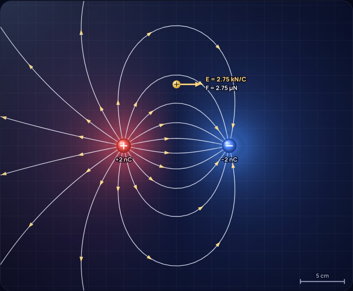
Between the charges the two fields point the same way, from + towards −, so they add. At the midpoint each charge is 6 cm away:
Worked example: the dipole at its midpoint and above it
Now move 7 cm straight up from the midpoint. Each charge is cm away and contributes kN/C. The vertical parts cancel and the horizontal parts, each a fraction 6/9.22 of that, add:
A 1 nC test charge there feels , pointing parallel to the axis, from the + side towards the − side.
The midpoint result is worth remembering. The field there is strong, almost 10 kN/C, yet the potential is zero. Field and potential are different things: the field is about the slope of the potential, not its value.
Two like charges and the null point
Now make both charges +2 nC. The lines from each charge bend away from the other one, and none of them join the two charges. Between the charges there is a gap with no lines at all, and in the middle of it the field is exactly zero.
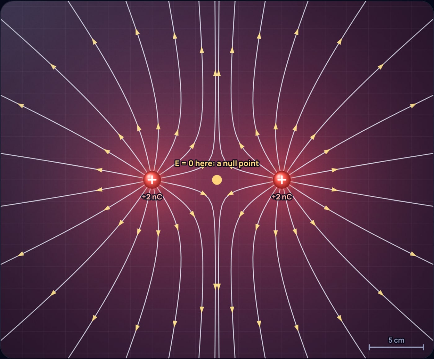
At the midpoint the two charges push a test charge with equal and opposite forces, so the net field is zero. This is the null point, and it is the only place two field lines can meet: with no field there is no direction, so the rule against crossing does not apply. The potential is not zero, though. Each charge contributes 300 V, so V. Move 7 cm up from the midpoint and the field rises to 3.21 kN/C, pointing straight up, away from both charges.
The repulsion you see in the diagram is real. The force between the two charges is
Faraday described field lines as if they were stretched rubber bands that also push sideways on each other. That picture is useful here: the lines between like charges push apart, which is a way of seeing why the charges repel.
Unequal charges: +3 nC and −1 nC
Unequal charges are where the line counting rule earns its place. A +3 nC charge sends out 24 lines, and a −1 nC charge only takes in 8. So 8 lines run from the big charge to the small one, and the other 16 have nowhere to end and head out to infinity. Far away, the pair looks like a single +2 nC charge, because that is the net charge.
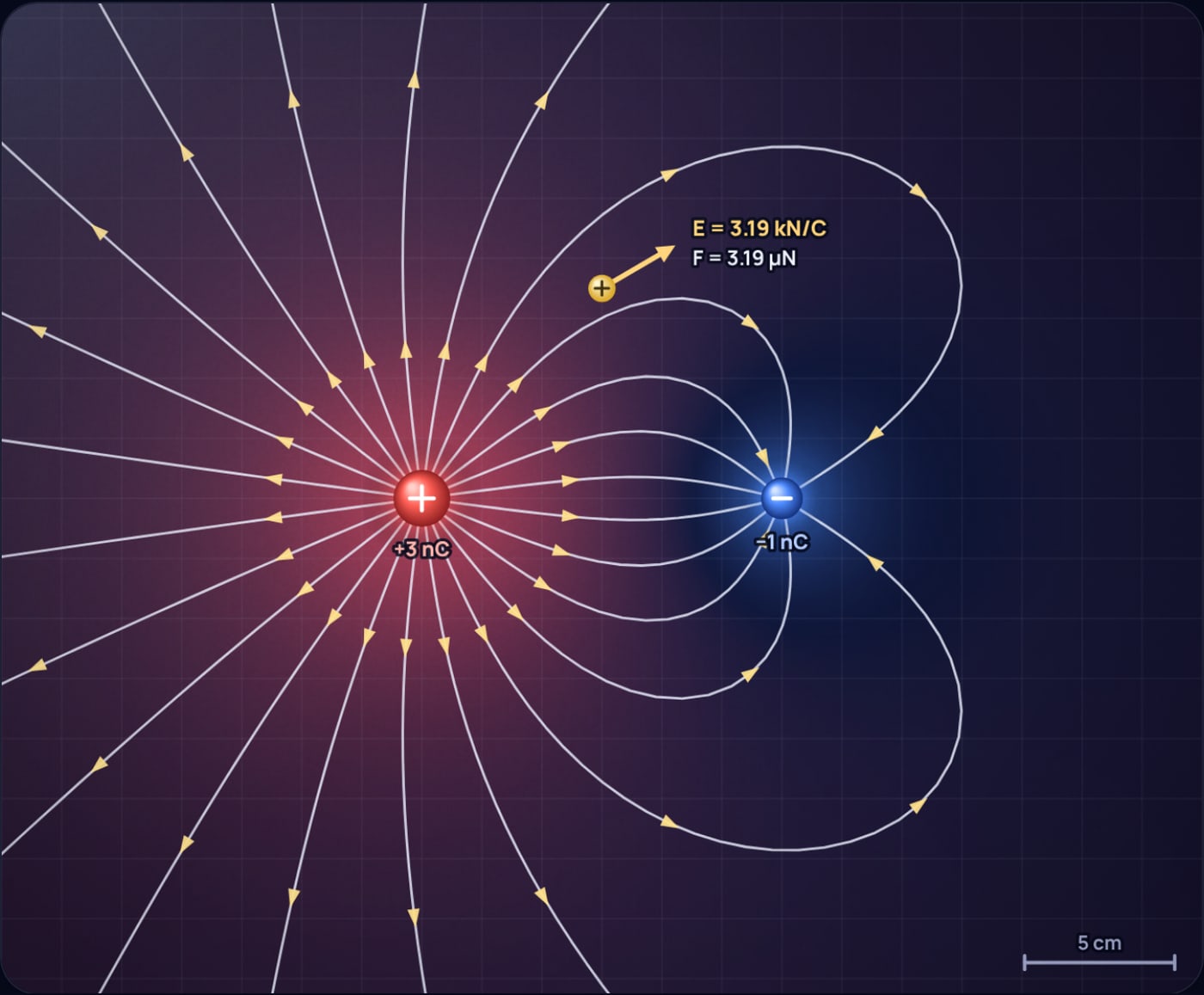
There is still a null point, but it is not between the charges. Between them both fields point towards the negative charge, so they cannot cancel. It sits outside, on the far side of the smaller charge, where the weak nearby charge balances the strong distant one. With the +3 nC charge at x = −6 cm and the −1 nC charge at x = +6 cm, call d the distance beyond the small charge:
So the null point is at x = 22.4 cm. In the simulator you can drag the test charge along the axis and watch the field fall to zero there and then reverse. The general rule: for opposite charges, the null point is outside the pair, nearer the smaller charge. For like charges it is between them, again nearer the smaller one.
Parallel plates: a nearly uniform field
A charged plate can be modelled as many point charges in a row. The simulator uses two rows of 11 charges, each ±0.5 nC, along lines 10 cm apart and 20 cm long. Between the rows the field lines run straight across and evenly spaced. Near the ends they bulge outwards. This bulge is called the fringing field.
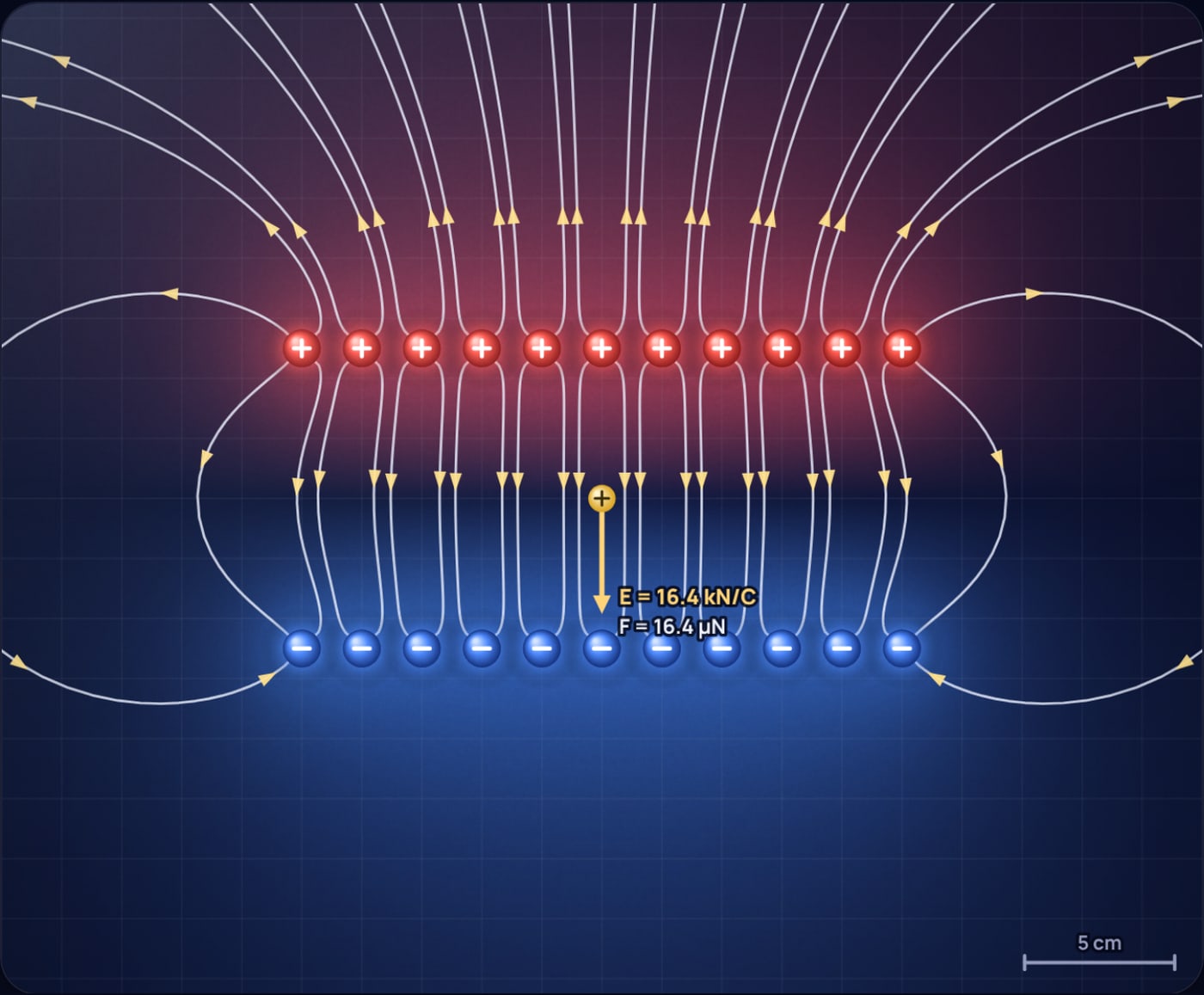
Straight, parallel, evenly spaced lines are the signature of a uniform field, and this is why a parallel plate capacitor is the standard way to make one. With the model in the simulator the field at the centre is 16.4 kN/C. It is 17.1 kN/C 1 cm above the centre and 19.9 kN/C 2 cm above, so it is close to uniform in the middle and grows as you approach a row of separate point charges. Real plates carry a continuous charge rather than 11 dots, and plates that are wide compared with their gap give a field that is uniform over almost the whole space between them.
Quadrupole: four charges, one null point
Place +2 nC and −2 nC charges alternately on the corners of a 12 cm square. Each positive charge sends its lines to the two negative neighbours, so the lines form four curved bundles around the edges of the square. At the centre everything cancels: the field is zero, and the potential is zero as well.
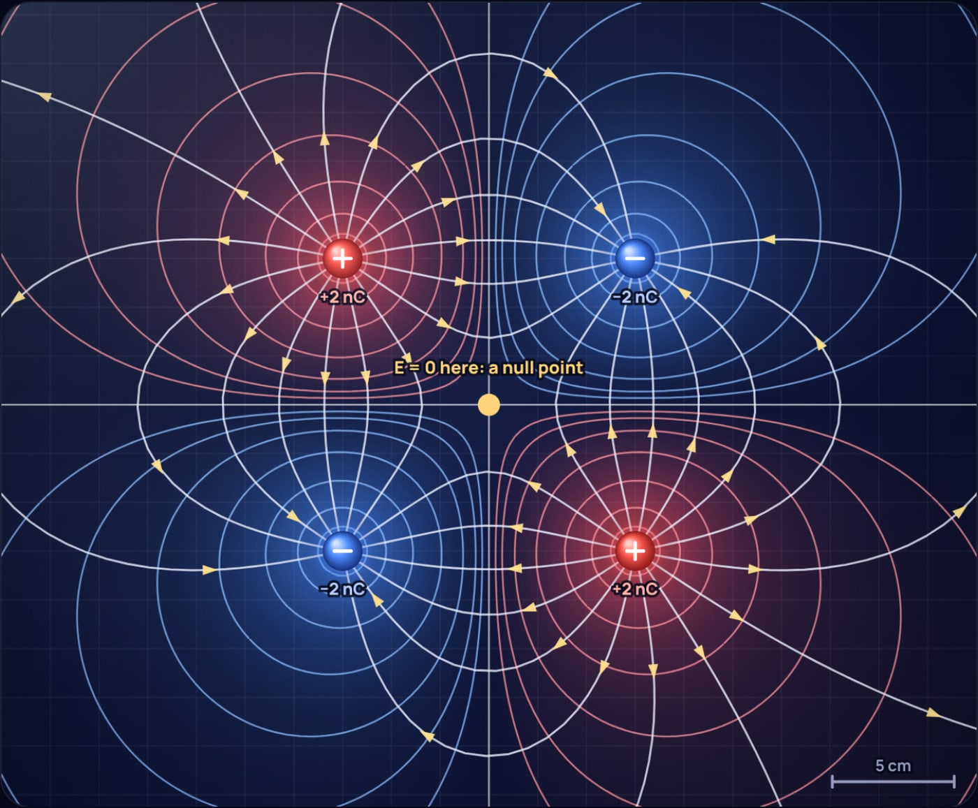
The field around the centre grows fast. At 4 cm above the centre it is already 7.17 kN/C. Because the net charge and the net dipole moment are both zero, the field far away falls off much faster than for a single charge or a dipole, which is why quadrupole lines stay close to the charges.
Equipotentials and the right angle rule
An equipotential is a line (in 3D, a surface) along which the potential is the same everywhere. Moving a charge along it takes no work, because . But work is force times displacement along the force. If no work is done for any small step along the equipotential, the field must have no component along it. So the field, and every field line, crosses each equipotential at 90°.
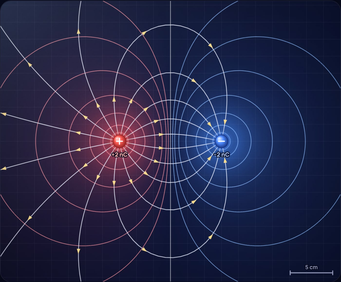
Close to a charge, the equipotentials are nearly circles, because that charge dominates. Halfway between the two charges of a dipole, the 0 V equipotential is a straight line: the perpendicular bisector. The equipotentials are also closest together where the field is strongest. That follows from : a steep fall in potential means a strong field.
Common mistakes in field line diagrams
- Drawing lines that cross. If your sketch has two lines crossing, one of them is wrong. Only at a null point do lines meet.
- Same number of lines on unequal charges. A +3 nC charge needs three times the lines of a −1 nC charge, and the extra lines must leave the picture.
- Lines joining like charges. Lines never run from one positive charge to another. They bend away from each other.
- Treating a field line as a path. A field line shows the direction of the force, not the path a charge would follow. A charge that starts moving will curve off the line because of its own inertia.
- Arrows missing. Without arrows a dipole diagram looks identical whichever charge is positive.
Try it yourself
The best way to make these rules stick is to break things and watch the lines respond. In the electric field lines simulator you can drag any charge, change its size and sign, add or remove charges, and move the test charge around to read the field, potential and force. Try pulling the two charges of a dipole far apart and watch the lines straighten, or make a pair of like charges unequal and follow the null point as it slides towards the smaller charge.
If you want to see what large fields do in the real world, read why birds sitting on a power line don't get electrocuted, what happens when a strong field pulls electrons off metal in a microwave, and how much energy a single lightning bolt really carries.
Sources
- NIST, CODATA 2022 value of the vacuum electric permittivity ε0 = 8.8541878188 × 10⁻¹² F/m: physics.nist.gov
- OpenStax, College Physics 2e, section 18.5 "Electric Field Lines: Multiple Charges" (the five properties of field lines): openstax.org
Frequently asked questions
Why do electric field lines never cross?
At any point the electric field has exactly one direction, and a field line points along that direction. If two lines crossed, the field at the crossing would point two ways at once, which is impossible. The only places where lines seem to meet are null points, where the field is zero and has no direction at all.
Where do electric field lines start and end?
They start on positive charges and end on negative charges. If the charges are not balanced, the extra lines run off to infinity, or come in from infinity to end on the extra negative charge.
What does the spacing of field lines tell you?
How strong the field is. Where lines crowd together the field is strong, and where they spread apart it is weak. Around a single point charge the lines spread over a sphere, so their density falls as 1/r squared, the same way Coulomb’s law does.
Is the electric field zero between two like charges?
Only at one point. For two equal positive charges the field is zero exactly midway between them, the null point. Everywhere else on the line joining them it points away from the nearer charge. The potential at that point is not zero; for two 2 nC charges 12 cm apart it is about 599 V.
Are equipotential lines always perpendicular to field lines?
Yes. Moving along an equipotential takes no work, so the field can have no component along it. That means the field, and every field line, crosses each equipotential at a right angle.
 50 Hilarious Physics Jokes That Will Make You Laugh
 Could Ant-Man Really Shrink? The Physics Says No