Where can a spacecraft keep pace with two orbiting bodies?
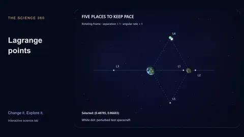
The five Lagrange points are equilibria in the frame rotating with two bodies on circular orbits. A tiny third body can share their orbital angular speed at these locations.
Select a system and a starting point, then give the spacecraft a small velocity nudge. The trajectory is integrated in the rotating frame, including centrifugal and Coriolis terms. One separation and one orbital angular rate are the units.
Read the companion article for a worked investigation, or continue with kepler orbits.
What to look for
- L1, L2 and L3 are unstable in this model.
- L4 and L5 form equilateral triangles with the primaries; linear stability requires μ(1 − μ) < 1/27.
- The Sun–Earth and Earth–Moon mass ratios meet that criterion; equal masses do not.
Experiments to try
Load a complete preset, predict what will change, then adjust one control and compare the live measurements.
Earth–Moon L4
Guided experimentA small velocity nudge near Earth–Moon L4 produces bounded motion over the displayed interval. Both major bodies stay fixed on screen because the camera rotates with their circular orbit.
Sun–Earth L2
Guided experimentL2 is just beyond Earth, viewed from the Sun. The small separation is true to this normalized scale, so its marker sits very close to Earth. A velocity perturbation grows; the point is unstable without station keeping.
Equal-mass L4
Guided experimentAn equilateral L4 position still exists for equal masses, but it is no longer linearly stable. Existence and stability are separate questions. Compare its trail with the low-mass-ratio case.
Compare the cases
| System | μ | L4 / L5 linear stability |
|---|---|---|
| Sun–Earth | 0.000003003 | Stable |
| Earth–Moon | 0.0121506 | Stable |
| Equal masses | 0.5 | Unstable |
Rounded values and classifications refer to the model and assumptions on this page.
How the model works
The three collinear positions are roots of the rotating-frame force equation, solved by bisection. The triangular positions are x = 1/2 − μ and y = ±√3/2, where μ is the secondary’s share of total mass.
A fourth-order Runge–Kutta integrator advances a massless spacecraft. Playback covers 12.8 normalized time units, about two primary revolutions. Paths stop early at a close encounter or on leaving the illustrated domain. This is not a mission-design tool.
What the model leaves out
- Circular primary orbits, planar motion and a massless spacecraft only.
- No solar perturbations in Earth–Moon mode, navigation errors or station-keeping burns.
- The dots for bodies and points are enlarged; real mission halo orbits are three dimensional.
Common misconceptions
A spacecraft at L1 or L2 is not beyond gravity. Gravity supplies its required orbital acceleration. JWST and Aditya-L1 travel around their selected equilibrium regions rather than sitting motionless in inertial space.
Frequently asked questions
Why is L2 useful for JWST?
Its Sun–Earth geometry supports thermal shielding and observations. This planar experiment illustrates the equilibrium region, not JWST’s actual halo trajectory.
Why does an unnudged point appear stationary?
An ideal equilibrium with exactly matching velocity can stay fixed in the rotating frame. Instability means small errors grow; it does not mean a perfectly exact equilibrium is mathematically impossible.
Keep learning
Lagrange points explained: the geometry behind JWST and Aditya-L1
Understand the five rotating-frame equilibrium points, why L1 and L2 need station keeping, and what makes L4 and L5 different.