How Much Current Can a 10 mil Trace Carry? PCB Widths From 4 to 50 mil
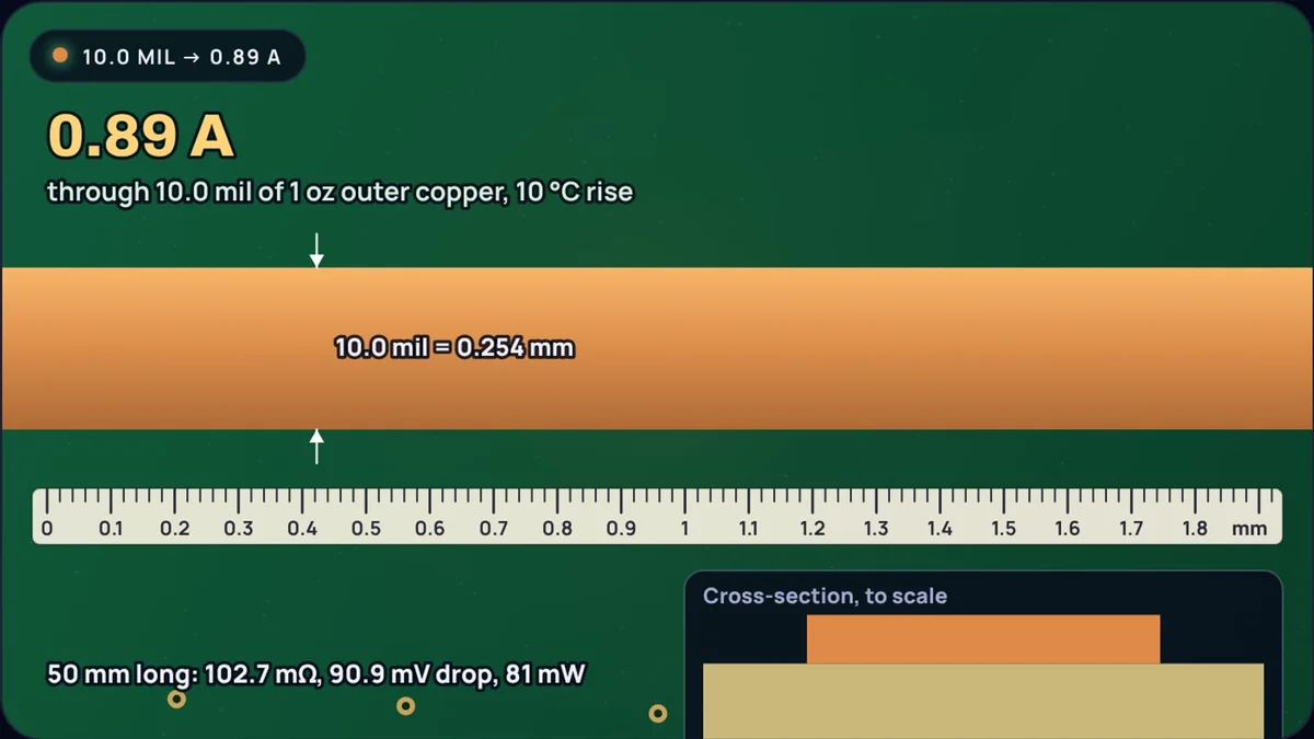
Ten mil, 0.254 mm, is the trace width many PCB tools start you on. It is narrow enough to route between pins and wide enough for most board houses to etch reliably. Sooner or later it ends up carrying more than a logic signal: an LED, a sensor's supply, a small relay coil. So how much current is too much?
By IPC-2221, the standard most trace calculators use, a 10 mil trace on 1 oz outer copper carries about 0.89 A with a 10 °C temperature rise. The PCB trace width calculator gives the current for any width, or the width for any current, and draws the trace to scale against a ruler; every number here comes from it.
Where the number comes from
IPC-2221 gives charts of current against copper cross-section for several temperature rises. Calculators use a curve fit to those charts; the version Advanced Circuits publishes with its calculator is:
Here A is the copper cross-section in square mil, ΔT the temperature rise in °C, and k = 0.048 for outer layers in air or 0.024 for inner layers. Copper weight sets the thickness: one ounce per square foot is 1.378 mil, about 35 µm.
Example 1: a 10 mil trace on 1 oz outer copper, 10 °C rise
Allow 20 °C instead and 100.44 becomes 200.44 = 3.737, giving 1.20 A.
Where those constants come from, why the internal chart is suspect, and how the newer IPC-2152 data compares, are covered in PCB trace width for current: IPC-2221 vs IPC-2152. This post stays with the practical question: what does each common width carry?
Current for common trace widths
| Width | mm | Outer, 10 °C | Outer, 20 °C | Outer, 30 °C | Inner, 10 °C | Outer 2 oz, 10 °C |
|---|---|---|---|---|---|---|
| 4 mil | 0.102 | 0.46 A | 0.62 A | 0.74 A | 0.23 A | 0.75 A |
| 6 mil | 0.152 | 0.61 A | 0.83 A | 0.99 A | 0.31 A | 1.01 A |
| 8 mil | 0.203 | 0.75 A | 1.02 A | 1.22 A | 0.38 A | 1.25 A |
| 10 mil | 0.254 | 0.89 A | 1.20 A | 1.44 A | 0.44 A | 1.46 A |
| 12 mil | 0.305 | 1.01 A | 1.37 A | 1.64 A | 0.51 A | 1.67 A |
| 15 mil | 0.381 | 1.19 A | 1.61 A | 1.93 A | 0.59 A | 1.96 A |
| 20 mil | 0.508 | 1.46 A | 1.99 A | 2.37 A | 0.73 A | 2.42 A |
| 30 mil | 0.762 | 1.96 A | 2.66 A | 3.18 A | 0.98 A | 3.25 A |
| 50 mil | 1.270 | 2.84 A | 3.86 A | 4.61 A | 1.42 A | 4.70 A |
The charts behind the fit cover 10 to 100 °C of rise, 0.5 to 3 oz copper, up to 35 A and up to 400 mil, so everything in this table sits inside them.
Doubling the width does not double the current
Look down the table: 10 mil carries 0.89 A, 20 mil carries 1.46 A. Twice the copper gives 65% more current, not 100%. The exponent 0.725 is the reason. A wider trace has more cross-section to carry current, but its surface area for shedding heat grows more slowly in comparison, so each extra mil is worth a little less.
Turned around, a trace for twice the current must be 21/0.725 = 2.6 times as wide. The same factor appears between inner and outer layers, because IPC-2221 allows inner traces half the current.
Which temperature rise should you use?
A 10 °C rise is the usual conservative choice, and the one most tables quote. 20 °C is common for power traces on boards that are not in a hot enclosure. Above that, remember that the rise adds to the ambient: a board inside a 50 °C box with a 30 °C rise puts the copper at 80 °C, and FR-4 and nearby parts have to live with it.
Going from a 10 °C to a 20 °C allowance raises the current by 20.44 = 1.36 times. That is a cheaper way to carry 1.2 A on 10 mil than widening the trace, but only if the heat has somewhere to go.
Inner layers and thicker copper
IPC-2221 halves the current for buried traces. Michael Jouppi, writing about the new IPC-2152 standard, noted that the internal chart was not based on testing internal conductors, and that testing showed internal and external traces have close to the same temperature rise. The calculator still shows the IPC-2221 inner figure because it is what most checks expect, but treat it as a safe floor rather than a measurement.
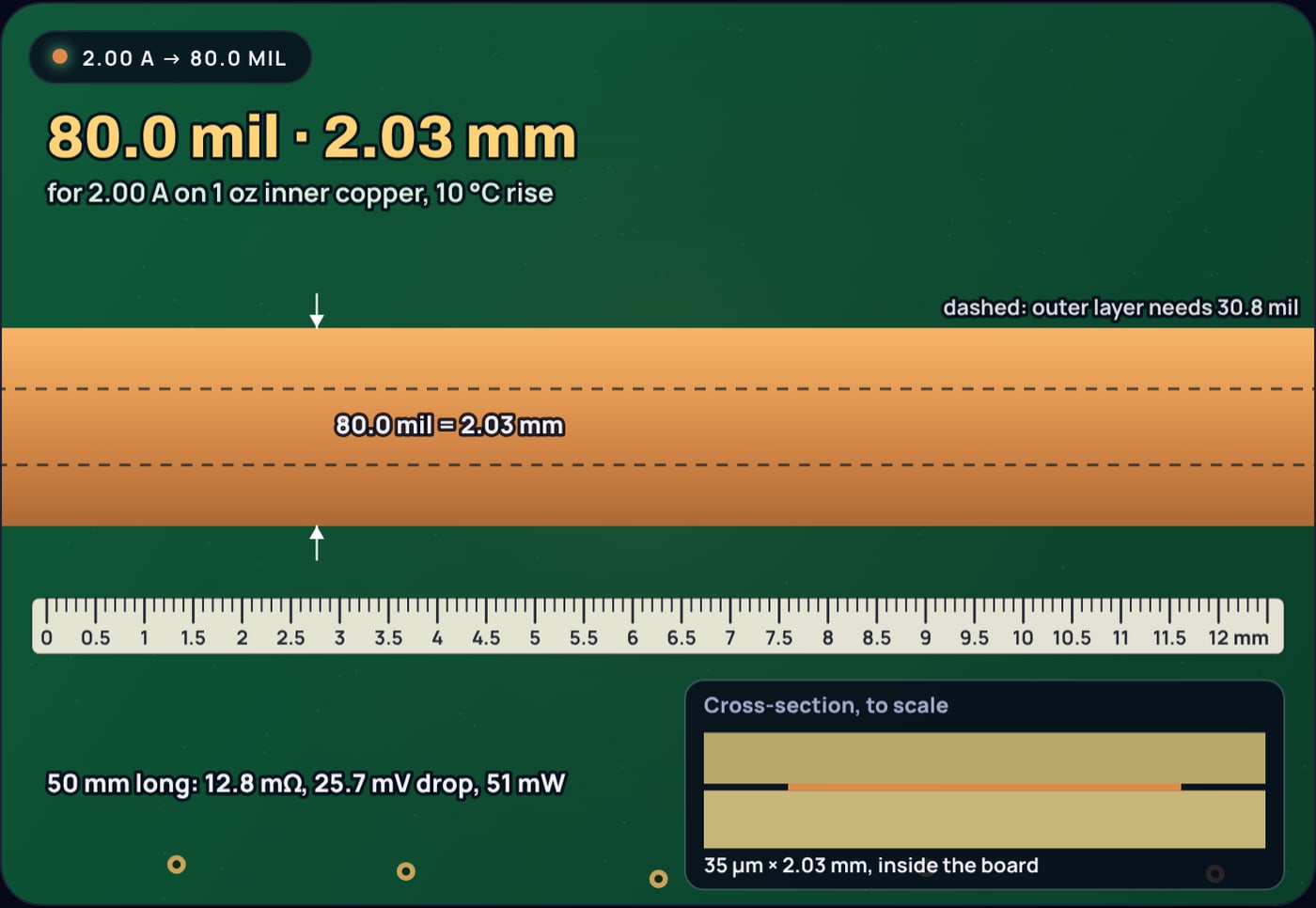
Copper weight works through area. A 10 mil trace in 2 oz copper has the same cross-section as a 20 mil trace in 1 oz, so it carries the same 1.46 A. Outer layers are also plated during manufacture: NCAB describes the IPC finished-copper table as foil plus an average of 20 µm of plating, so a "1 oz" outer trace usually ends up thicker than 35 µm, adding margin.
How much voltage does a 10 mil trace drop?
Heat is one limit; voltage drop is the other, and on thin traces it often matters first. Copper's resistivity is 1/58 Ω·mm²/m at 20 °C and rises 0.393% per °C, by the NBS copper wire tables.
Example 2: 100 mm of 10 mil, 1 oz trace at 0.5 A
A tenth of a volt is 3% of a 3.3 V rail, from a trace that is nowhere near its thermal limit. For supply lines, check the drop as well as the width.
When 10 mil is not enough
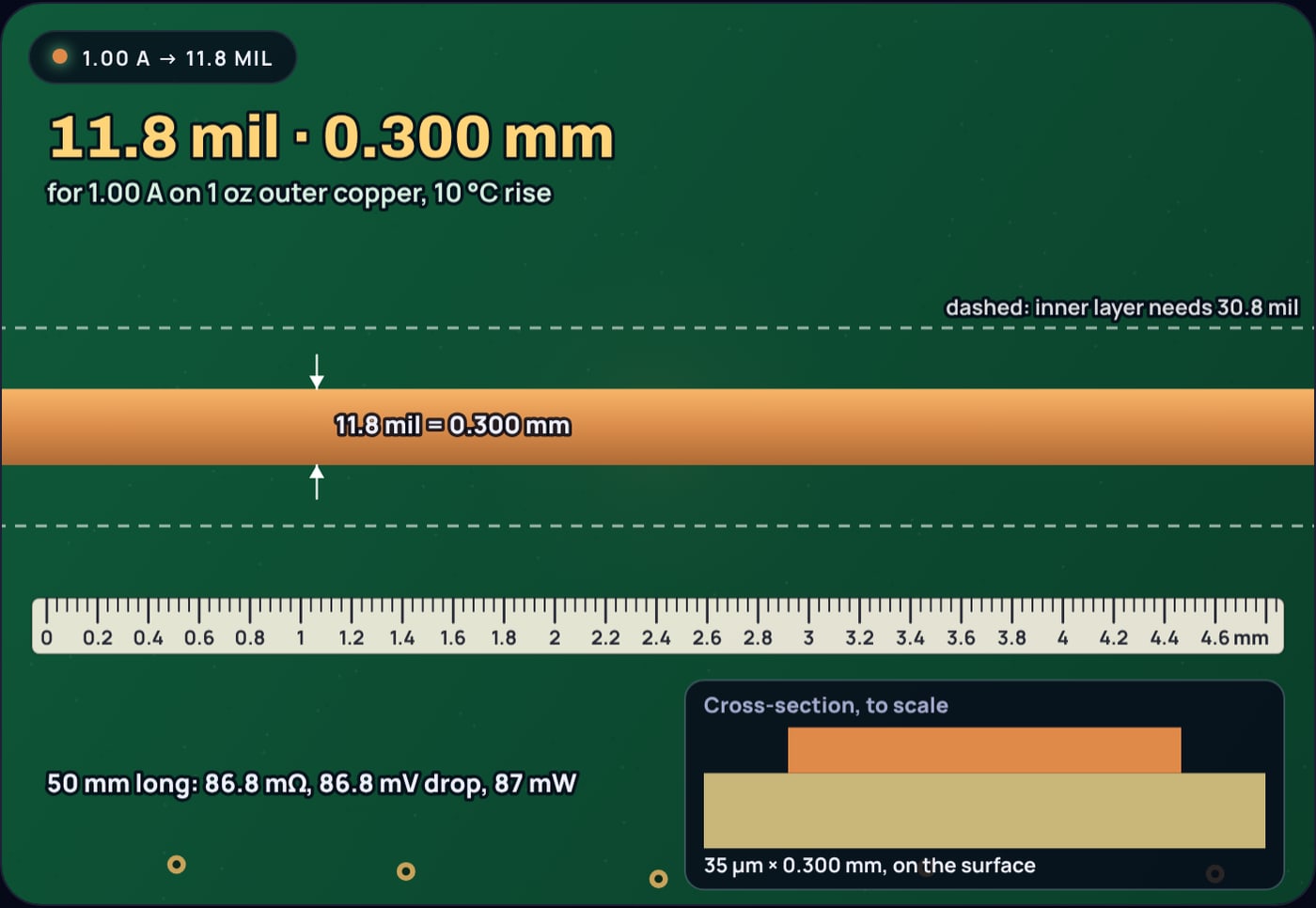
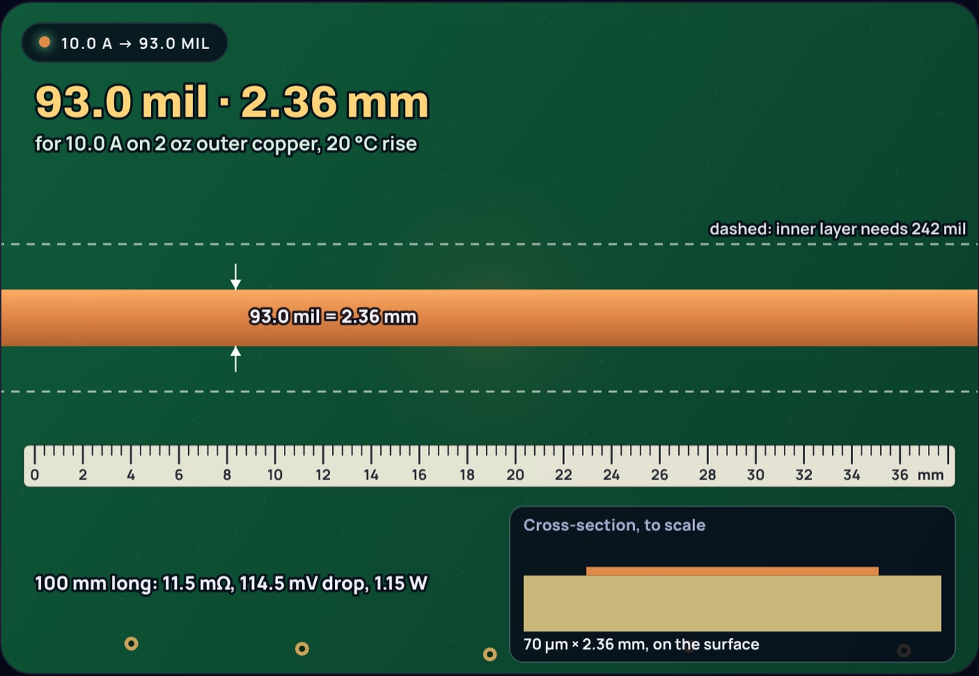
Above about an amp, widths grow quickly. 5 A on 2 oz outer copper needs about 109 mil; 10 A on 2 oz copper with a 20 °C allowance needs 93 mil, 2.36 mm. At that point, copper pours, planes or several layers in parallel are usually easier than one wide trace.
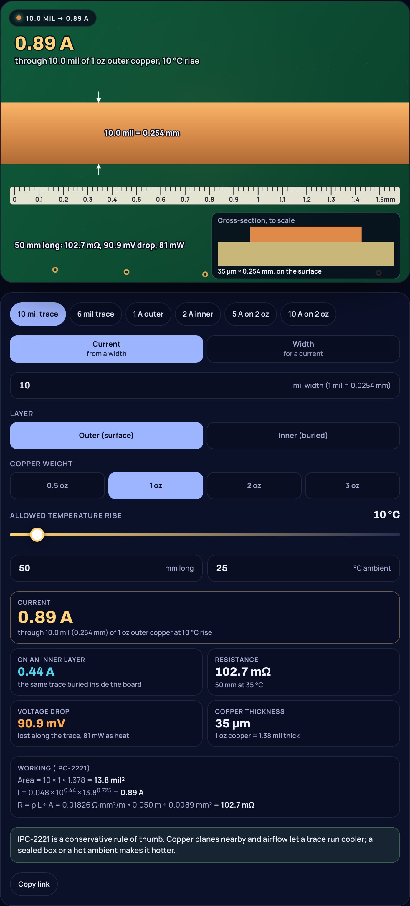
To check your own traces, open the PCB trace width calculator, switch between finding a current and finding a width, and set the copper weight, layer and temperature rise your board needs.
Sources
- Advanced Circuits: Trace Width Calculator (IPC-2221 curve fit: k = 0.048 external, 0.024 internal, b = 0.44, c = 0.725, 1.378 mil per oz; charts cover up to 35 A, 0.4 inch, 10 to 100 °C, 0.5 to 3 oz)
- Michael Jouppi, "The New IPC-2152", Printed Circuit Design & Fab (internal chart not based on testing internal conductors; internal and external rise close to the same)
- Ruben Contreras, NCAB, "How Do You Calculate Finished Copper?", I-Connect007 (finished outer copper = foil minimum plus about 20 µm average plating)
- NBS Handbook 100, Copper Wire Tables (resistivity 1/58 = 0.017241 Ω·mm²/m and temperature coefficient 0.00393 at 20 °C)
Frequently asked questions
How much current can a 10 mil trace carry?
About 0.89 A on 1 oz outer copper for a 10 °C temperature rise, 1.2 A for a 20 °C rise and 1.44 A for 30 °C, by the IPC-2221 curve fit. On an inner layer IPC-2221 allows half: 0.44 A at 10 °C.
How much current can a 6 mil trace carry?
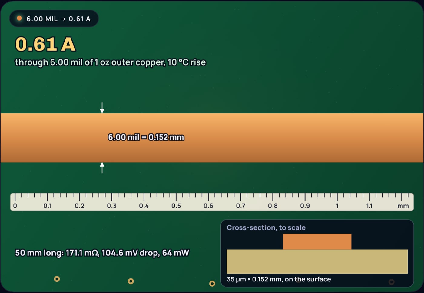
About 0.61 A on 1 oz outer copper for a 10 °C rise and 0.83 A for 20 °C, by IPC-2221. On an inner layer, about 0.31 A at 10 °C.
Does doubling the trace width double the current?
No. In IPC-2221 current grows with the copper area to the power 0.725, so doubling the width raises the current by about 65%: a 20 mil trace carries 1.46 A against 0.89 A for 10 mil at a 10 °C rise.
How wide is 10 mil in mm?
0.254 mm. One mil is a thousandth of an inch, 0.0254 mm.
Is 1 A too much for a 10 mil trace?
On 1 oz outer copper it means a rise of about 13 °C by IPC-2221, which most boards tolerate. On an inner layer or in a hot enclosure, go wider; 12 mil keeps 1 A to a 10 °C rise on the surface.