
1.1. Introduction
This document provides detailed information for the assembly, programming, and operation of the Improved Capacitive Soil Moisture Sensor. This sensor is designed to provide a more reliable and durable alternative to common resistive soil moisture sensors by measuring the dielectric constant of the soil, which is directly proportional to its water content.
The sensor is controlled by an ATtiny85 microcontroller and communicates with a master device over the I2C protocol, making it easy to integrate into a wide variety of projects, including automated watering systems, environmental monitoring stations, and IoT applications.
1.2. Key Features
- Capacitive Sensing: Avoids electrode corrosion for longer sensor life and more stable readings.
- ATtiny85 Microcontroller: A low-power, cost-effective, and powerful core for sensor operation.
- I2C Interface: Allows for simple communication with a master device and supports connecting multiple sensors on a single bus (daisy-chaining).
- Onboard Logic: The sensor handles the measurement process internally and outputs a processed digital value.
- ISP Header: Allows for easy in-system programming of the microcontroller.
2. Hardware
2.1. Theory of Operation
The sensor functions as a capacitor where the two probes (J4, J5) act as the capacitor plates and the surrounding soil acts as the dielectric medium. The principle is based on the fact that water has a much higher dielectric constant than dry soil.
The measurement process is as follows:
- The ATtiny85 microcontroller (U1) uses a digital pin (PB4) to charge the sensor probe (J4) through resistor R1.
- The pin’s state is then flipped, allowing the charge to dissipate through the soil to the other probe (J5).
- The ATtiny85’s analog-to-digital converter (ADC) on pin PB3 measures the time it takes for the voltage to fall below a certain threshold.
- This discharge time is directly proportional to the capacitance of the soil.
- Wet Soil: Higher capacitance -> Slower discharge -> Longer time measurement.
- Dry Soil: Lower capacitance -> Faster discharge -> Shorter time measurement.
- The measured time is then mapped to a digital value and made available over the I2C bus.
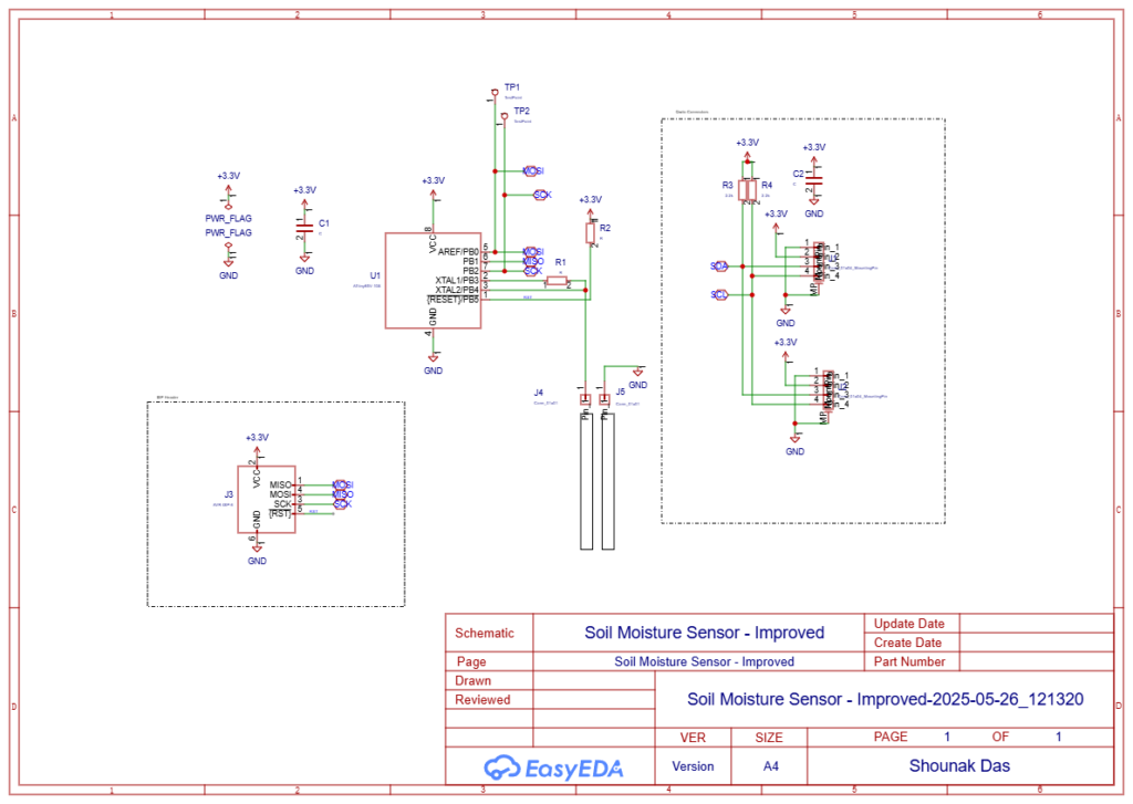
2.2. Schematic Breakdown
The circuit is designed for simplicity and efficiency.
- U1 (ATtiny85): The core of the sensor. It controls the charge/discharge cycle, measures the time, and handles I2C communication.
- J4, J5 (Sensor Probes): These are the connections for the capacitive probes that will be inserted into the soil.
- C1 (10uF): A decoupling capacitor to stabilize the power supply to the ATtiny85.
- R1, R2 (Resistors): These form part of the RC oscillator circuit used for the measurement. Their values affect the sensitivity and range of the sensor.
- R3, R4 (2.2kΩ): Pull-up resistors for the I2C communication lines (SDA and SCL). These are required for the I2C protocol to function correctly.
- J1, J2 (I2C/Power Connectors): Standard 4-pin headers for providing power (+3.3V, GND) and I2C communication (SDA, SCL).
- J3 (ISP Header): A 2×3 pin header for In-System Programming, allowing you to upload firmware to the ATtiny85 without removing it from the board.
- TP1, TP2 (Test Points): Provide easy access for debugging and verifying voltage levels.
2.3. Bill of Materials (BOM)
| No. | Quantity | Designator | Footprint | Value |
| 1 | 2 | C1, C2 | Capacitor, SMD | 10uF |
| 2 | 2 | J1, J2 | Conn_01x04_MountingPin | 4-pin Header |
| 3 | 1 | J3 | AVR-ISP-6 | 2×3 Header |
| 4 | 2 | J4, J5 | Conn_01x01 | 1-pin Header |
| 5 | 2 | R1, R2 | Resistor, SMD 0805 | 1MΩ (Typical) |
| 6 | 2 | R3, R4 | Resistor, SMD 0805 | 2.2kΩ |
| 7 | 2 | TP1, TP2 | TestPoint | Test Point |
| 8 | 1 | U1 | SOIC-8 | ATtiny85 |
Note: Values for R1 and R2 can be experimented with to adjust sensor sensitivity.
3. Firmware
3.1. Programming the ATtiny85
The firmware for the ATtiny85 needs to be uploaded via the ISP header (J3). You will need an AVR programmer, such as a USBasp, or you can configure an Arduino Uno as an ISP.
Connections for Arduino as ISP:
- Connect the Arduino’s 5V/3.3V and GND to the sensor’s VCC and GND.
- Connect Arduino pins 13, 12, 11, and 10 to the sensor’s SCK, MISO, MOSI, and RESET pins on the ISP header, respectively.
Software:
- Use the Arduino IDE with the ATtinyCore board manager installed.
- Select “ATtiny25/45/85” as the board, “ATtiny85” as the processor, and your programmer of choice.
- Burn the bootloader (to set the correct fuses, e.g., for the internal 8MHz clock).
- Upload the sensor sketch.
3.2. Logic Flow
The firmware should perform the following steps in a loop:
- Initialize: Set up pin modes and start the I2C communication interface with a unique device address.
- Charge: Set the charge pin (PB4) to HIGH to charge the probe.
- Discharge & Measure: Set the charge pin to INPUT (high impedance) and start a timer. Continuously read the analog pin (PB3) until its value drops below a predefined threshold. Stop the timer.
- Store Value: The elapsed time is the raw moisture reading. Store this value in a variable that can be accessed via I2C.
- I2C Request Handler: Set up an interrupt service routine (ISR) that listens for requests from the I2C master. When a request is received, send the stored moisture value back to the master.
- Delay: Wait for a short period before taking the next measurement to conserve power and prevent self-heating.
3.3. I2C Communication
- Default Address: The firmware should be programmed with a default I2C address (e.g.,
0x2A). If you plan to daisy-chain sensors, you must program each one with a unique address. - Data Format: The master device can request data from the sensor’s address. The sensor will respond with a 2-byte integer representing the raw moisture reading (0-1023).
4. Integration and Usage
4.1. Connecting to a Master Device (e.g., Arduino)
- Connect the sensor’s VCC and GND pins to the Arduino’s 3.3V and GND pins.
- Connect the sensor’s SDA pin to the Arduino’s A4 pin (SDA).
- Connect the sensor’s SCL pin to the Arduino’s A5 pin (SCL).
- In your Arduino sketch, use the
Wire.hlibrary to request data from the sensor’s I2C address.
4.2. Calibration
For accurate readings, a two-point calibration is recommended.
- Dry Reading: Place the sensor in completely dry soil and record the raw value from the sensor. This is your
dryValue. - Wet Reading: Submerge the sensor in a glass of water and record the raw value. This is your
wetValue. - Mapping: Use these two values in your master device’s code to map the sensor’s output to a percentage (0-100%).
4.3. Daisy-Chaining
You can connect multiple sensors to the same I2C bus.
- Ensure all sensors are connected in parallel (all SDA lines together, all SCL lines together).
- Crucially, each sensor must be programmed with a unique I2C address.
- The master device can then poll each sensor individually by addressing it specifically.