
")
The 74HC595 shift register is one of the most widely used ICs in electronics, embedded systems, and prototyping. Its ability to expand digital output pins makes it essential in LED control, multiplexing, display driving, robotics, and compact embedded designs.
This comprehensive guide explains how the 74HC595 works, its internal architecture, pinout, timing, features, advantages, and multiple control methods using Arduino, ESP32, STM32, AVR, ARM and other microcontrollers.
What Is the 74HC595 Shift Register?
The 74HC595 is an 8-bit serial-in, parallel-out (SIPO) shift register with latch storage. It allows you to control 8 digital outputs using only 3 microcontroller pins.
By daisy-chaining multiple 74HC595 ICs, you can expand outputs to 16, 24, 32 or more pins without increasing your microcontroller’s GPIO usage.
It is commonly used in:
- LED bar graphs
- 7-segment displays
- LED matrices
- Relay boards
- Keypad interfaces
- Robotics
- Digital indicators and dashboards
- Projects requiring many output pins
Why Use the 74HC595?
Modern microcontrollers like Arduino UNO, ATmega, ESP8266, ESP32, nRF52, and STM32 have limited GPIO pins. The 74HC595 solves this problem by converting serial data into parallel outputs while requiring only three control lines:
- Serial Data (DS)
- Shift Clock (SHCP)
- Latch Clock (STCP)
This allows:
- Reduced wiring
- More compact PCB design
- Efficient output expansion
- Faster switching using hardware SPI
- Clean, scalable output architectures
74HC595 Pinout
Total Pins: 16
Below is a fast-reading explanation of each pin and its function.
| Pin | Name | Type | Function |
|---|---|---|---|
| 1 | Q1 | Output | Bit 1 output |
| 2 | Q2 | Output | Bit 2 output |
| 3 | Q3 | Output | Bit 3 output |
| 4 | Q4 | Output | Bit 4 output |
| 5 | Q5 | Output | Bit 5 output |
| 6 | Q6 | Output | Bit 6 output |
| 7 | Q7 | Output | Bit 7 output |
| 8 | GND | Power | Ground |
| 9 | Q7’ | Output | Serial out for cascading |
| 10 | MR | Input | Active-low reset |
| 11 | SHCP | Input | Shift clock |
| 12 | STCP | Input | Latch clock |
| 13 | OE | Input | Output enable (active-low) |
| 14 | DS | Input | Serial data input |
| 15 | Q0 | Output | Bit 0 output |
| 16 | VCC | Power | +5 V or +3.3 V |
Internal Architecture and Working Principle
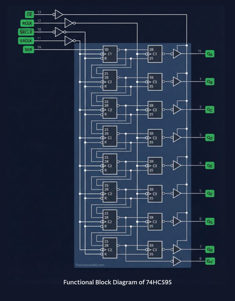
The 74HC595 consists of:
- 8-bit shift register
- 8-bit storage latch
- Three control signals (DS, SHCP, STCP)
Step-by-step data flow
- Serial data enters via DS
- Each rising edge of SHCP shifts the data through the register
- The entire 8 bits stay hidden until the latch is triggered
- A rising edge on STCP transfers shift-register data into the output latch
- Q0–Q7 update simultaneously
This dual-register structure ensures flicker-free output updates.
Key Features of the 74HC595
- Operates at 2 V to 6 V
- Works with 5 V Arduino and 3.3 V microcontrollers
- 8-bit parallel output with serial input
- Max operating frequency: 100 MHz at 5V
- Tri-state output controlled via OE pin
- Cascadable using Q7’
- Low power consumption
- High-speed CMOS technology
- Wide temperature range for industrial use
- Suitable for LED driving, digital logic control, and multiplexing
How to Control the 74HC595 Using Arduino
This section is heavily optimized for keyword ranking such as Arduino 74HC595 tutorial, control 74HC595 Arduino, Arduino shift register example, etc.
Diagram
Essential Arduino Connections:
- Pin 14 (DS) → Arduino D11 (MOSI)
- Pin 11 (SHCP) → Arduino D13 (SCK)
- Pin 12 (STCP) → Arduino D10 (Latch)
- Pin 13 (OE) → GND
- Pin 10 (MR) → VCC
- VCC → 5V
- GND → GND
Arduino Code: Basic LED Control
This example shifts a single bit flowing from Q0 to Q7.
int latchPin = 10;
int clockPin = 13;
int dataPin  = 11;

void setup() {
  pinMode(latchPin, OUTPUT);
  pinMode(clockPin, OUTPUT);
  pinMode(dataPin, OUTPUT);
}

void loop() {
  for (int i = 0; i < 8; i++) {
    digitalWrite(latchPin, LOW);
    shiftOut(dataPin, clockPin, MSBFIRST, 1 << i);
    digitalWrite(latchPin, HIGH);
    delay(200);
  }
}
Arduino Example: Control All LEDs Individually
byte leds = 0;

void loop() {
  leds = 0b10101010;
  digitalWrite(latchPin, LOW);
  shiftOut(dataPin, clockPin, MSBFIRST, leds);
  digitalWrite(latchPin, HIGH);
}
Using Hardware SPI for Faster Output
Using Arduino’s SPI.h library greatly increases speed.
#include <SPI.h>

const int latchPin = 10;

void setup() {
  SPI.begin();
  pinMode(latchPin, OUTPUT);
}

void loop() {
  digitalWrite(latchPin, LOW);
  SPI.transfer(0b11110000);
  digitalWrite(latchPin, HIGH);
}
Hardware SPI can achieve much higher switching speeds ideal for:
- LED matrices
- Fast refresh displays
- Multiplexed systems
- POV devices
Cascading Multiple 74HC595 ICs
To expand outputs, connect:
- Q7’ of first IC → DS of second IC
- Share SHCP and STCP across all ICs
Example: Two 74HC595 provide 16 outputs
digitalWrite(latchPin, LOW);
shiftOut(dataPin, clockPin, MSBFIRST, highByte(data));
shiftOut(dataPin, clockPin, MSBFIRST, lowByte(data));
digitalWrite(latchPin, HIGH);
This lets you control LED strips, stepper motors, or 7-segment displays with minimal pins.
Controlling 74HC595 Using Other Microcontrollers
This section increases search coverage for keywords such as STM32, ESP32, nRF52, ATmega, PIC, and ARM.
1. ESP32 / ESP8266
- Operates at 3.3V
- Fully supports shiftOut and hardware SPI
- Perfect for IoT dashboards and LED control
ESP32 Sample Code
SPI.begin(18, 19, 23);
digitalWrite(latchPin, LOW);
SPI.transfer(0xAA);
digitalWrite(latchPin, HIGH);
2. STM32 (HAL Libraries)
HAL_GPIO_WritePin(LATCH_GPIO_Port, LATCH_Pin, GPIO_PIN_RESET);
uint8_t value = 0xF0;
HAL_SPI_Transmit(&hspi1, &value, 1, 10);
HAL_GPIO_WritePin(LATCH_GPIO_Port, LATCH_Pin, GPIO_PIN_SET);
STM32’s high-speed SPI makes it suitable for display multiplexing.
3. AVR / ATmega (Bare-Metal C)
SPDR = data;
while(!(SPSR & (1<<SPIF)));
Bare-metal control offers precise timing.
4. nRF52 (Bluetooth SoCs)
Perfect for wearable devices, low-power embedded projects, and remote LED indicators.
Applications of the 74HC595
LED Driving
Drive 8 LEDs directly or use resistors for current limiting.
7-Segment Display Control
Using 2–4 cascaded registers to manage:
- Digits
- Segments
- Decimal points
Relay Board Control
Enables 8-channel or 16-channel relays using only 3 pins.
Stepper Motor Control
With ULN2003 or transistor arrays for load driving.
LED Matrix Control
Used in multiplexing systems for 8×8, 16×8 matrices.
Industrial Control Panels
Cost-efficient digital indicators with isolation and buffering.
Electrical Characteristics and Timing (For Engineering Readers)
- Supply voltage: 2V–6V
- Input logic high: 0.7VCC
- Output current: ±6 mA per pin
- Max clock frequency: 100 MHz
- Propagation delay: 8–12 ns
Timing requirements:
- SHCP rising edge shifts data
- STCP rising edge latches data
- OE low enables outputs
- MR low resets shift register
If using high loads, pair the IC with:
- Transistor drivers
- MOSFET arrays
- ULN2803, ULN2003
- LED drivers
Best Practices for Stable Operation
Use Decoupling Capacitors
Place a 100 nF ceramic capacitor near VCC and GND.
Avoid Driving High Currents Directly
Use transistors or MOSFETs for:
- Motors
- High-brightness LEDs
- Relays
Keep Clock Lines Short
High-speed signals like SHCP and STCP should be short to avoid noise.
Use Hardware SPI for Large Chains
Improves speed and stability.
Consider PCB layout
Route the ground and power traces thick. Keep clock traces isolated from noisy power routes.
Troubleshooting Common Issues
| Problem | Cause | Solution |
|---|---|---|
| LEDs flicker | Latch timing issue | Ensure proper STCP pulse |
| Incorrect output order | Wrong bit order | Use MSBFIRST or LSBFIRST correctly |
| No output | OE not tied low | Ensure OE = GND |
| Reset issues | MR pulled low | Pull MR high |
| Cascaded ICs misbehave | Clock skew | Shorter wires, hardware SPI |
Conclusion
The 74HC595 shift register is one of the most versatile, cost-effective, and widely used ICs for digital output expansion. With only three control lines, it enables microcontrollers like Arduino, ESP32, STM32, ATmega, nRF52, and PIC to control dozens or even hundreds of outputs efficiently.