
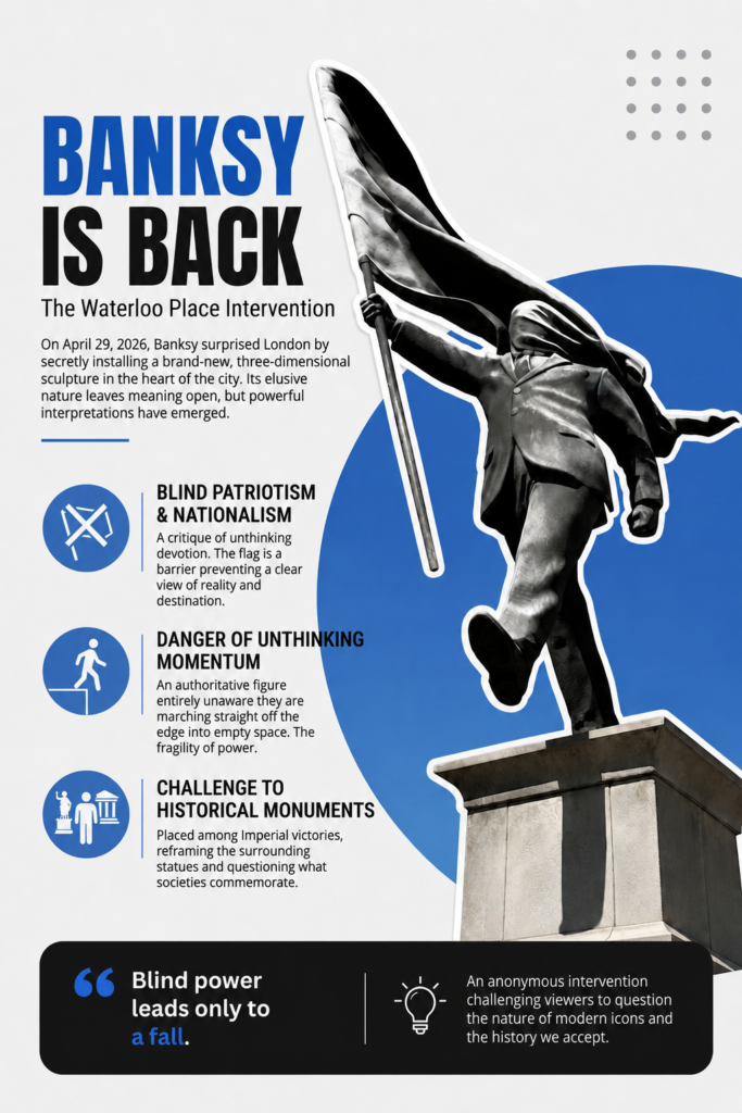
If you happened to take a morning stroll through the heart of central London recently, you might have noticed an unexpected addition to the historic landscape. On the morning of April 29, 2026, commuters passing through St James’s were greeted by a striking new piece of public art. Placed covertly in Waterloo Place, the sculpture immediately drew crowds, sparked intense debate, and dominated social media across the globe. Soon after, the elusive street artist Banksy claimed responsibility for the piece, cementing its status as a major cultural event.
For those who follow contemporary art, a new Banksy installation is always a thrilling moment. But this artwork feels distinctly different. It is not a spray-painted mural hastily stenciled onto a brick wall in the dead of night. Instead, Banksy has presented the public with a formidable, three-dimensional statue. It is a bold, heavy, and deeply provocative piece that challenges both the physical space it occupies and the people who walk past it.
People immediately began asking questions. What is the meaning of Banksy’s new art? Why did he choose a medium he so rarely uses? And most importantly, why did he place this specific statue in an area of London absolutely saturated with British imperial history?
If you are fascinated by political satire, modern art, or just love decoding a good mystery, you have come to the right place. We are going to take a deep dive into the symbolism, the brilliant location choice, and the profound message behind the new Banksy statue in London.
Table of Contents
- Unpacking the Visuals of the London Flag Statue
- The Core Message of Blind Nationalism
- Why the Waterloo Place Location is a Masterstroke
- The Significance of a Three-Dimensional Statue
- The Unexpected Reaction from Local Authorities
- A Timely Warning for the Modern World
- Experience the Art While You Still Can
Unpacking the Visuals of the London Flag Statue
Understanding the visual elements of the artwork is the first step to unlocking its meaning. The sculpture, which art experts believe is crafted from fiberglass or resin, is life-sized and remarkably detailed. It depicts a man dressed in a sharp, formal business suit. He is striding forward with an undeniable sense of purpose and confidence. In his hand, he is aggressively hoisting a massive flag on a pole.
However, there is a critical twist. The wind has blown the heavy fabric of the flag violently backward. The material wraps entirely around the man’s head, completely covering his eyes, his nose, and his mouth. He is entirely blinded by the very symbol he so proudly waves.
The danger of his situation becomes clear when you look at his feet. Blinded by the flag, the suited man is captured mid-stride. He is stepping confidently off the edge of the stone plinth into thin air. There is no ground beneath his leading foot. He is walking directly toward a steep and inevitable fall.
A simple, characteristic scrawl at the base of the plinth initially hinted at the creator. The artist officially claimed the piece shortly after on his Instagram account. He posted a video showing the stealthy overnight installation using a flatbed truck. The video was set to the stirring, highly patriotic sounds of Edward Elgar’s Pomp and Circumstance March No. 1. In a touch of classic Banksy humor, the video ends with a random passerby looking at the new artwork, pointing at the older historical monuments nearby, and stating bluntly that he does not like the new addition.
The Core Message of Blind Nationalism
When it comes to this elusive artist, the message is rarely subtle, yet it always carries layers of profound social commentary. Art critics, historians, and casual observers were quick to decode the primary meaning of the London statue. It is a razor-sharp critique of blind patriotism and the dangerous allure of unquestioned nationalism.
Flags are universally recognized symbols of national pride, cultural identity, and unity. They bring people together under a shared cause. However, in this artwork, the flag transforms from a symbol of empowerment into a literal and dangerous blindfold. Banksy is suggesting that an obsession with nationalism prevents us from seeing the reality of the world around us. When patriotism crosses the line into zealotry or tribal loyalty, it obscures our vision. It blinds us to the negative consequences of our actions and the actions of our leaders.
The choice of clothing for the figure is equally important. Banksy did not sculpt a weary soldier or an everyday working class citizen. He sculpted an establishment figure. The sharp suit represents politicians, corporate leaders, bureaucrats, and those in positions of institutional power. These are often the very people who wave the flag the hardest to drum up public support. They use nationalistic rhetoric to consolidate power, while simultaneously marching their societies into perilous situations.
The most powerful element of the sculpture is the man’s final, unsupported step. He is marching proudly, but because he cannot see past his own flag, he is stepping directly into the abyss. This acts as a grim and timely warning. Blind loyalty and unchecked nationalism inevitably lead to a disastrous downfall. If a society cannot see where it is going because its vision is obstructed by patriotic fervor, that society will eventually step off a ledge.
Why the Waterloo Place Location is a Masterstroke
To fully grasp the meaning of Banksy’s new art, you must look closely at where it was placed. Banksy is a master of environmental context. He does not just create art; he forces his art to interact with its surroundings in a meaningful way.
Waterloo Place is located in the St James’s area of central London. This specific location was heavily developed in the nineteenth century to celebrate British military dominance and imperial power. The area is essentially an open-air museum dedicated to British might. When the installation crew dropped the statue into place under the cover of darkness, they positioned it amidst heavily loaded historical company.
The new statue sits near the towering bronze of King Edward the Seventh. It shares space with the Florence Nightingale statue. Most notably, it sits near the Crimean War Memorial. The Crimean War is historically famous for disastrous military blunders driven by rigid leadership.
By inserting a modern critique of blind patriotism into a space dedicated to historic military glory, Banksy creates immediate artistic tension. He forces a silent but deafening conversation between the glorification of Britain’s imperial past and the stark realities of modern political tribalism. The placement asks pedestrians to look at the old statues celebrating the empire, and then look at the new statue warning against the very mindset that built that empire. London art dealer Philip Mould commented on this brilliance, noting how perfectly Banksy managed the proportions of the artwork to fit within this monumental space.
The Significance of a Three-Dimensional Statue
The medium itself is also a significant part of the message. While Banksy is globally recognized for his iconic spray-painted stencils, fully realized public sculptures are incredibly rare for him. For longtime followers of his work, this new installation echoes a stunt he pulled over two decades ago. In 2004, he illegally installed a statue called The Drinker in Shaftesbury Avenue. That piece was a satirical take on a famous Auguste Rodin statue, featuring a figure sitting with a traffic cone on its head.
Returning to the medium of public sculpture in 2026 makes a powerful statement. A painted mural can easily be scrubbed away or covered in plastic by local authorities. In fact, just a few months prior in September 2025, Banksy painted a mural on the Royal Courts of Justice depicting a judge beating a protester with a gavel. Authorities swiftly destroyed it.
A massive, heavy fiberglass statue requiring industrial trucks to install demands a completely different level of attention. It takes up physical space. It forces pedestrians to alter their path to walk around it. It asserts a commanding presence that a two-dimensional painting simply cannot achieve. By creating a statue, Banksy is demanding that his warning about blind nationalism be treated with the same physical weight as the historical monuments surrounding it.
The Unexpected Reaction from Local Authorities
The reaction from the public and local authorities has been entirely unprecedented. Usually, when unauthorized street art appears, local councils scramble to remove it, citing vandalism or public obstruction. However, the sheer cultural weight of the Banksy name has flipped the traditional script in Westminster.
The public reaction has been one of overwhelming fascination. Massive crowds swarmed Waterloo Place within hours of the discovery. Locals, international tourists, and art critics rushed to photograph the piece, fearing it might be taken down at any moment. As one young student observing the statue noted, public art by this artist is usually a limited time event, and you never know how long it will remain standing.
Surprisingly, the authorities have fully embraced the rogue installation. Westminster City Council released an official statement calling the work a striking addition to the vibrant public art scene of the city. Representatives for London Mayor Sadiq Khan also expressed great enthusiasm, stating that the artist has a unique ability to inspire people to enjoy modern art. They expressed hope that the piece could be preserved for the public for years to come.
Rather than bringing in cranes to tear it down, the local council actually erected protective safety barriers around the statue to prevent vandalism. The establishment, which is the very entity the suited statue appears to be mocking, is now spending government resources to protect and preserve it. It is a layer of supreme irony that the artist himself is undoubtedly enjoying.
A Timely Warning for the Modern World
Art does not exist in a vacuum, and Banksy has built a career on holding a mirror up to the current anxieties of society. The year 2026 has seen a continued rise in global polarization. Across the world, we are witnessing intense geopolitical conflicts, shifting borders, and political leaders leaning heavily into nationalist rhetoric to secure their own power.
In an era where social media algorithms trap us in echo chambers and political loyalty is demanded without question, this statue serves as a vital, urgent wake-up call. The flag blinded man represents any nation, any political party, and any individual who allows loyalty to a symbol to override their basic humanity and common sense.
The artwork asks every viewer a deeply uncomfortable question. What are you carrying that is blinding you to the truth? Are you so fiercely focused on marching forward for your specific cause or country that you do not realize there is no solid ground left to step on?
Experience the Art While You Still Can
Banksy’s new art in central London is far more than just a viral internet moment. It is an absolute masterclass in visual storytelling, historical location scouting, and biting political satire. By taking a brilliantly simple concept of a man blinded by his own flag and placing it directly in the heart of London’s imperial center, the artist has created one of the most poignant and important artworks of the decade.
Part of the enduring magic of street art is its inherently fleeting nature. Even though the local council has put up fences to protect it for now, unauthorized public art rarely lasts forever in its original location. It may eventually be moved to a secure indoor museum, purchased by a wealthy private collector, or it could mysteriously vanish in the night just as quickly as it appeared.
If you find yourself in London, make your way to Waterloo Place in St James’s to experience this incredible piece of cultural history while you still have the chance. Stand among the towering monuments of the past, look at the blinded man stepping off the ledge, and take a moment to reflect on the ground beneath your own feet. Because with Banksy, you truly never know when the final curtain will fall on the exhibition.


 400 a night.” Comet will then scour the web, compare options, and present you with a personalized itinerary.
![146 this month</strong> by leveraging legit beer money sites and testing platforms. <!-- /wp:paragraph --> <!-- wp:paragraph --> Let's dive in. <!-- /wp:paragraph --> <!-- wp:paragraph {"dropCapStyle":"dropcapp"} --> Summary Table: <!-- /wp:paragraph --> <!-- wp:html --> <style type="text/css">@import url("https://assets.mlcdn.com/fonts.css?version=1750852");</style> <style type="text/css"> /* LOADER */ .ml-form-embedSubmitLoad { display: inline-block; width: 20px; height: 20px; } .g-recaptcha { transform: scale(1); -webkit-transform: scale(1); transform-origin: 0 0; -webkit-transform-origin: 0 0; height: ; } .sr-only { position: absolute; width: 1px; height: 1px; padding: 0; margin: -1px; overflow: hidden; clip: rect(0,0,0,0); border: 0; } .ml-form-embedSubmitLoad:after { content: " "; display: block; width: 11px; height: 11px; margin: 1px; border-radius: 50%; border: 4px solid #fff; border-color: #ffffff #ffffff #ffffff transparent; animation: ml-form-embedSubmitLoad 1.2s linear infinite; } @keyframes ml-form-embedSubmitLoad { 0% { transform: rotate(0deg); } 100% { transform: rotate(360deg); } } #mlb2-27858390.ml-form-embedContainer { box-sizing: border-box; display: table; margin: 0 auto; position: static; width: 100% !important; } #mlb2-27858390.ml-form-embedContainer h4, #mlb2-27858390.ml-form-embedContainer p, #mlb2-27858390.ml-form-embedContainer span, #mlb2-27858390.ml-form-embedContainer button { text-transform: none !important; letter-spacing: normal !important; } #mlb2-27858390.ml-form-embedContainer .ml-form-embedWrapper { background-color: #f6f6f6; border-width: 0px; border-color: transparent; border-radius: 4px; border-style: solid; box-sizing: border-box; display: inline-block !important; margin: 0; padding: 0; position: relative; } #mlb2-27858390.ml-form-embedContainer .ml-form-embedWrapper.embedPopup, #mlb2-27858390.ml-form-embedContainer .ml-form-embedWrapper.embedDefault { width: 400px; } #mlb2-27858390.ml-form-embedContainer .ml-form-embedWrapper.embedForm { max-width: 400px; width: 100%; } #mlb2-27858390.ml-form-embedContainer .ml-form-align-left { text-align: left; } #mlb2-27858390.ml-form-embedContainer .ml-form-align-center { text-align: center; } #mlb2-27858390.ml-form-embedContainer .ml-form-align-default { display: table-cell !important; vertical-align: middle !important; text-align: center !important; } #mlb2-27858390.ml-form-embedContainer .ml-form-align-right { text-align: right; } #mlb2-27858390.ml-form-embedContainer .ml-form-embedWrapper .ml-form-embedHeader img { border-top-left-radius: 4px; border-top-right-radius: 4px; height: auto; margin: 0 auto !important; max-width: 100%; width: undefinedpx; } #mlb2-27858390.ml-form-embedContainer .ml-form-embedWrapper .ml-form-embedBody, #mlb2-27858390.ml-form-embedContainer .ml-form-embedWrapper .ml-form-successBody { padding: 20px 20px 0 20px; } #mlb2-27858390.ml-form-embedContainer .ml-form-embedWrapper .ml-form-embedBody.ml-form-embedBodyHorizontal { padding-bottom: 0; } #mlb2-27858390.ml-form-embedContainer .ml-form-embedWrapper .ml-form-embedBody .ml-form-embedContent, #mlb2-27858390.ml-form-embedContainer .ml-form-embedWrapper .ml-form-successBody .ml-form-successContent { text-align: left; margin: 0 0 20px 0; } #mlb2-27858390.ml-form-embedContainer .ml-form-embedWrapper .ml-form-embedBody .ml-form-embedContent h4, #mlb2-27858390.ml-form-embedContainer .ml-form-embedWrapper .ml-form-successBody .ml-form-successContent h4 { color: #000000; font-family: 'Open Sans', Arial, Helvetica, sans-serif; font-size: 30px; font-weight: 400; margin: 0 0 10px 0; text-align: left; word-break: break-word; } #mlb2-27858390.ml-form-embedContainer .ml-form-embedWrapper .ml-form-embedBody .ml-form-embedContent p, #mlb2-27858390.ml-form-embedContainer .ml-form-embedWrapper .ml-form-successBody .ml-form-successContent p { color: #000000; font-family: 'Open Sans', Arial, Helvetica, sans-serif; font-size: 14px; font-weight: 400; line-height: 20px; margin: 0 0 10px 0; text-align: left; } #mlb2-27858390.ml-form-embedContainer .ml-form-embedWrapper .ml-form-embedBody .ml-form-embedContent ul, #mlb2-27858390.ml-form-embedContainer .ml-form-embedWrapper .ml-form-embedBody .ml-form-embedContent ol, #mlb2-27858390.ml-form-embedContainer .ml-form-embedWrapper .ml-form-successBody .ml-form-successContent ul, #mlb2-27858390.ml-form-embedContainer .ml-form-embedWrapper .ml-form-successBody .ml-form-successContent ol { color: #000000; font-family: 'Open Sans', Arial, Helvetica, sans-serif; font-size: 14px; } #mlb2-27858390.ml-form-embedContainer .ml-form-embedWrapper .ml-form-embedBody .ml-form-embedContent ol ol, #mlb2-27858390.ml-form-embedContainer .ml-form-embedWrapper .ml-form-successBody .ml-form-successContent ol ol { list-style-type: lower-alpha; } #mlb2-27858390.ml-form-embedContainer .ml-form-embedWrapper .ml-form-embedBody .ml-form-embedContent ol ol ol, #mlb2-27858390.ml-form-embedContainer .ml-form-embedWrapper .ml-form-successBody .ml-form-successContent ol ol ol { list-style-type: lower-roman; } #mlb2-27858390.ml-form-embedContainer .ml-form-embedWrapper .ml-form-embedBody .ml-form-embedContent p a, #mlb2-27858390.ml-form-embedContainer .ml-form-embedWrapper .ml-form-successBody .ml-form-successContent p a { color: #000000; text-decoration: underline; } #mlb2-27858390.ml-form-embedContainer .ml-form-embedWrapper .ml-block-form .ml-field-group { text-align: left!important; } #mlb2-27858390.ml-form-embedContainer .ml-form-embedWrapper .ml-block-form .ml-field-group label { margin-bottom: 5px; color: #333333; font-size: 14px; font-family: 'Open Sans', Arial, Helvetica, sans-serif; font-weight: bold; font-style: normal; text-decoration: none;; display: inline-block; line-height: 20px; } #mlb2-27858390.ml-form-embedContainer .ml-form-embedWrapper .ml-form-embedBody .ml-form-embedContent p:last-child, #mlb2-27858390.ml-form-embedContainer .ml-form-embedWrapper .ml-form-successBody .ml-form-successContent p:last-child { margin: 0; } #mlb2-27858390.ml-form-embedContainer .ml-form-embedWrapper .ml-form-embedBody form { margin: 0; width: 100%; } #mlb2-27858390.ml-form-embedContainer .ml-form-embedWrapper .ml-form-embedBody .ml-form-formContent, #mlb2-27858390.ml-form-embedContainer .ml-form-embedWrapper .ml-form-embedBody .ml-form-checkboxRow { margin: 0 0 20px 0; width: 100%; } #mlb2-27858390.ml-form-embedContainer .ml-form-embedWrapper .ml-form-embedBody .ml-form-checkboxRow { float: left; } #mlb2-27858390.ml-form-embedContainer .ml-form-embedWrapper .ml-form-embedBody .ml-form-formContent.horozintalForm { margin: 0; padding: 0 0 20px 0; width: 100%; height: auto; float: left; } #mlb2-27858390.ml-form-embedContainer .ml-form-embedWrapper .ml-form-embedBody .ml-form-fieldRow { margin: 0 0 10px 0; width: 100%; } #mlb2-27858390.ml-form-embedContainer .ml-form-embedWrapper .ml-form-embedBody .ml-form-fieldRow.ml-last-item { margin: 0; } #mlb2-27858390.ml-form-embedContainer .ml-form-embedWrapper .ml-form-embedBody .ml-form-fieldRow.ml-formfieldHorizintal { margin: 0; } #mlb2-27858390.ml-form-embedContainer .ml-form-embedWrapper .ml-form-embedBody .ml-form-fieldRow input { background-color: #ffffff !important; color: #333333 !important; border-color: #cccccc; border-radius: 4px !important; border-style: solid !important; border-width: 1px !important; font-family: 'Open Sans', Arial, Helvetica, sans-serif; font-size: 14px !important; height: auto; line-height: 21px !important; margin-bottom: 0; margin-top: 0; margin-left: 0; margin-right: 0; padding: 10px 10px !important; width: 100% !important; box-sizing: border-box !important; max-width: 100% !important; } #mlb2-27858390.ml-form-embedContainer .ml-form-embedWrapper .ml-form-embedBody .ml-form-fieldRow input::-webkit-input-placeholder, #mlb2-27858390.ml-form-embedContainer .ml-form-embedWrapper .ml-form-embedBody .ml-form-horizontalRow input::-webkit-input-placeholder { color: #333333; } #mlb2-27858390.ml-form-embedContainer .ml-form-embedWrapper .ml-form-embedBody .ml-form-fieldRow input::-moz-placeholder, #mlb2-27858390.ml-form-embedContainer .ml-form-embedWrapper .ml-form-embedBody .ml-form-horizontalRow input::-moz-placeholder { color: #333333; } #mlb2-27858390.ml-form-embedContainer .ml-form-embedWrapper .ml-form-embedBody .ml-form-fieldRow input:-ms-input-placeholder, #mlb2-27858390.ml-form-embedContainer .ml-form-embedWrapper .ml-form-embedBody .ml-form-horizontalRow input:-ms-input-placeholder { color: #333333; } #mlb2-27858390.ml-form-embedContainer .ml-form-embedWrapper .ml-form-embedBody .ml-form-fieldRow input:-moz-placeholder, #mlb2-27858390.ml-form-embedContainer .ml-form-embedWrapper .ml-form-embedBody .ml-form-horizontalRow input:-moz-placeholder { color: #333333; } #mlb2-27858390.ml-form-embedContainer .ml-form-embedWrapper .ml-form-embedBody .ml-form-fieldRow textarea, #mlb2-27858390.ml-form-embedContainer .ml-form-embedWrapper .ml-form-embedBody .ml-form-horizontalRow textarea { background-color: #ffffff !important; color: #333333 !important; border-color: #cccccc; border-radius: 4px !important; border-style: solid !important; border-width: 1px !important; font-family: 'Open Sans', Arial, Helvetica, sans-serif; font-size: 14px !important; height: auto; line-height: 21px !important; margin-bottom: 0; margin-top: 0; padding: 10px 10px !important; width: 100% !important; box-sizing: border-box !important; max-width: 100% !important; } #mlb2-27858390.ml-form-embedContainer .ml-form-embedWrapper .ml-form-embedBody .ml-form-fieldRow .custom-radio .custom-control-label::before, #mlb2-27858390.ml-form-embedContainer .ml-form-embedWrapper .ml-form-embedBody .ml-form-horizontalRow .custom-radio .custom-control-label::before, #mlb2-27858390.ml-form-embedContainer .ml-form-embedWrapper .ml-form-embedBody .ml-form-fieldRow .custom-checkbox .custom-control-label::before, #mlb2-27858390.ml-form-embedContainer .ml-form-embedWrapper .ml-form-embedBody .ml-form-horizontalRow .custom-checkbox .custom-control-label::before, #mlb2-27858390.ml-form-embedContainer .ml-form-embedWrapper .ml-form-embedBody .ml-form-embedPermissions .ml-form-embedPermissionsOptionsCheckbox .label-description::before, #mlb2-27858390.ml-form-embedContainer .ml-form-embedWrapper .ml-form-embedBody .ml-form-interestGroupsRow .ml-form-interestGroupsRowCheckbox .label-description::before, #mlb2-27858390.ml-form-embedContainer .ml-form-embedWrapper .ml-form-embedBody .ml-form-checkboxRow .label-description::before { border-color: #cccccc!important; background-color: #ffffff!important; } #mlb2-27858390.ml-form-embedContainer .ml-form-embedWrapper .ml-form-embedBody .ml-form-fieldRow input.custom-control-input[type="checkbox"]{ box-sizing: border-box; padding: 0; position: absolute; z-index: -1; opacity: 0; margin-top: 5px; margin-left: -1.5rem; overflow: visible; } #mlb2-27858390.ml-form-embedContainer .ml-form-embedWrapper .ml-form-embedBody .ml-form-fieldRow .custom-checkbox .custom-control-label::before, #mlb2-27858390.ml-form-embedContainer .ml-form-embedWrapper .ml-form-embedBody .ml-form-horizontalRow .custom-checkbox .custom-control-label::before, #mlb2-27858390.ml-form-embedContainer .ml-form-embedWrapper .ml-form-embedBody .ml-form-embedPermissions .ml-form-embedPermissionsOptionsCheckbox .label-description::before, #mlb2-27858390.ml-form-embedContainer .ml-form-embedWrapper .ml-form-embedBody .ml-form-interestGroupsRow .ml-form-interestGroupsRowCheckbox .label-description::before, #mlb2-27858390.ml-form-embedContainer .ml-form-embedWrapper .ml-form-embedBody .ml-form-checkboxRow .label-description::before { border-radius: 4px!important; } #mlb2-27858390.ml-form-embedContainer .ml-form-embedWrapper .ml-form-embedBody .ml-form-checkboxRow input[type=checkbox]:checked~.label-description::after, #mlb2-27858390.ml-form-embedContainer .ml-form-embedWrapper .ml-form-embedBody .ml-form-embedPermissions .ml-form-embedPermissionsOptionsCheckbox input[type=checkbox]:checked~.label-description::after, #mlb2-27858390.ml-form-embedContainer .ml-form-embedWrapper .ml-form-embedBody .ml-form-fieldRow .custom-checkbox .custom-control-input:checked~.custom-control-label::after, #mlb2-27858390.ml-form-embedContainer .ml-form-embedWrapper .ml-form-embedBody .ml-form-horizontalRow .custom-checkbox .custom-control-input:checked~.custom-control-label::after, #mlb2-27858390.ml-form-embedContainer .ml-form-embedWrapper .ml-form-embedBody .ml-form-interestGroupsRow .ml-form-interestGroupsRowCheckbox input[type=checkbox]:checked~.label-description::after { background-image: url("data:image/svg+xml,%3csvg xmlns='http://www.w3.org/2000/svg' viewBox='0 0 8 8'%3e%3cpath fill='%23fff' d='M6.564.75l-3.59 3.612-1.538-1.55L0 4.26 2.974 7.25 8 2.193z'/%3e%3c/svg%3e"); } #mlb2-27858390.ml-form-embedContainer .ml-form-embedWrapper .ml-form-embedBody .ml-form-fieldRow .custom-radio .custom-control-input:checked~.custom-control-label::after, #mlb2-27858390.ml-form-embedContainer .ml-form-embedWrapper .ml-form-embedBody .ml-form-fieldRow .custom-radio .custom-control-input:checked~.custom-control-label::after { background-image: url("data:image/svg+xml,%3csvg xmlns='http://www.w3.org/2000/svg' viewBox='-4 -4 8 8'%3e%3ccircle r='3' fill='%23fff'/%3e%3c/svg%3e"); } #mlb2-27858390.ml-form-embedContainer .ml-form-embedWrapper .ml-form-embedBody .ml-form-fieldRow .custom-radio .custom-control-input:checked~.custom-control-label::before, #mlb2-27858390.ml-form-embedContainer .ml-form-embedWrapper .ml-form-embedBody .ml-form-horizontalRow .custom-radio .custom-control-input:checked~.custom-control-label::before, #mlb2-27858390.ml-form-embedContainer .ml-form-embedWrapper .ml-form-embedBody .ml-form-fieldRow .custom-checkbox .custom-control-input:checked~.custom-control-label::before, #mlb2-27858390.ml-form-embedContainer .ml-form-embedWrapper .ml-form-embedBody .ml-form-horizontalRow .custom-checkbox .custom-control-input:checked~.custom-control-label::before, #mlb2-27858390.ml-form-embedContainer .ml-form-embedWrapper .ml-form-embedBody .ml-form-embedPermissions .ml-form-embedPermissionsOptionsCheckbox input[type=checkbox]:checked~.label-description::before, #mlb2-27858390.ml-form-embedContainer .ml-form-embedWrapper .ml-form-embedBody .ml-form-interestGroupsRow .ml-form-interestGroupsRowCheckbox input[type=checkbox]:checked~.label-description::before, #mlb2-27858390.ml-form-embedContainer .ml-form-embedWrapper .ml-form-embedBody .ml-form-checkboxRow input[type=checkbox]:checked~.label-description::before { border-color: #000000!important; background-color: #000000!important; } #mlb2-27858390.ml-form-embedContainer .ml-form-embedWrapper .ml-form-embedBody .ml-form-fieldRow .custom-radio .custom-control-label::before, #mlb2-27858390.ml-form-embedContainer .ml-form-embedWrapper .ml-form-embedBody .ml-form-horizontalRow .custom-radio .custom-control-label::before, #mlb2-27858390.ml-form-embedContainer .ml-form-embedWrapper .ml-form-embedBody .ml-form-fieldRow .custom-radio .custom-control-label::after, #mlb2-27858390.ml-form-embedContainer .ml-form-embedWrapper .ml-form-embedBody .ml-form-horizontalRow .custom-radio .custom-control-label::after, #mlb2-27858390.ml-form-embedContainer .ml-form-embedWrapper .ml-form-embedBody .ml-form-fieldRow .custom-checkbox .custom-control-label::before, #mlb2-27858390.ml-form-embedContainer .ml-form-embedWrapper .ml-form-embedBody .ml-form-fieldRow .custom-checkbox .custom-control-label::after, #mlb2-27858390.ml-form-embedContainer .ml-form-embedWrapper .ml-form-embedBody .ml-form-horizontalRow .custom-checkbox .custom-control-label::before, #mlb2-27858390.ml-form-embedContainer .ml-form-embedWrapper .ml-form-embedBody .ml-form-horizontalRow .custom-checkbox .custom-control-label::after { top: 2px; box-sizing: border-box; } #mlb2-27858390.ml-form-embedContainer .ml-form-embedWrapper .ml-form-embedBody .ml-form-embedPermissions .ml-form-embedPermissionsOptionsCheckbox .label-description::before, #mlb2-27858390.ml-form-embedContainer .ml-form-embedWrapper .ml-form-embedBody .ml-form-embedPermissions .ml-form-embedPermissionsOptionsCheckbox .label-description::after, #mlb2-27858390.ml-form-embedContainer .ml-form-embedWrapper .ml-form-embedBody .ml-form-checkboxRow .label-description::before, #mlb2-27858390.ml-form-embedContainer .ml-form-embedWrapper .ml-form-embedBody .ml-form-checkboxRow .label-description::after { top: 0px!important; box-sizing: border-box!important; } #mlb2-27858390.ml-form-embedContainer .ml-form-embedWrapper .ml-form-embedBody .ml-form-checkboxRow .label-description::before, #mlb2-27858390.ml-form-embedContainer .ml-form-embedWrapper .ml-form-embedBody .ml-form-checkboxRow .label-description::after { top: 0px!important; box-sizing: border-box!important; } #mlb2-27858390.ml-form-embedContainer .ml-form-embedWrapper .ml-form-embedBody .ml-form-interestGroupsRow .ml-form-interestGroupsRowCheckbox .label-description::after { top: 0px!important; box-sizing: border-box!important; position: absolute; left: -1.5rem; display: block; width: 1rem; height: 1rem; content: ""; } #mlb2-27858390.ml-form-embedContainer .ml-form-embedWrapper .ml-form-embedBody .ml-form-interestGroupsRow .ml-form-interestGroupsRowCheckbox .label-description::before { top: 0px!important; box-sizing: border-box!important; } #mlb2-27858390.ml-form-embedContainer .ml-form-embedWrapper .ml-form-embedBody .custom-control-label::before { position: absolute; top: 4px; left: -1.5rem; display: block; width: 16px; height: 16px; pointer-events: none; content: ""; background-color: #ffffff; border: #adb5bd solid 1px; border-radius: 50%; } #mlb2-27858390.ml-form-embedContainer .ml-form-embedWrapper .ml-form-embedBody .custom-control-label::after { position: absolute; top: 2px!important; left: -1.5rem; display: block; width: 1rem; height: 1rem; content: ""; } #mlb2-27858390.ml-form-embedContainer .ml-form-embedWrapper .ml-form-embedBody .ml-form-embedPermissions .ml-form-embedPermissionsOptionsCheckbox .label-description::before, #mlb2-27858390.ml-form-embedContainer .ml-form-embedWrapper .ml-form-embedBody .ml-form-interestGroupsRow .ml-form-interestGroupsRowCheckbox .label-description::before, #mlb2-27858390.ml-form-embedContainer .ml-form-embedWrapper .ml-form-embedBody .ml-form-checkboxRow .label-description::before { position: absolute; top: 4px; left: -1.5rem; display: block; width: 16px; height: 16px; pointer-events: none; content: ""; background-color: #ffffff; border: #adb5bd solid 1px; border-radius: 50%; } #mlb2-27858390.ml-form-embedContainer .ml-form-embedWrapper .ml-form-embedBody .ml-form-embedPermissions .ml-form-embedPermissionsOptionsCheckbox .label-description::after { position: absolute; top: 0px!important; left: -1.5rem; display: block; width: 1rem; height: 1rem; content: ""; } #mlb2-27858390.ml-form-embedContainer .ml-form-embedWrapper .ml-form-embedBody .ml-form-checkboxRow .label-description::after { position: absolute; top: 0px!important; left: -1.5rem; display: block; width: 1rem; height: 1rem; content: ""; } #mlb2-27858390.ml-form-embedContainer .ml-form-embedWrapper .ml-form-embedBody .custom-radio .custom-control-label::after { background: no-repeat 50%/50% 50%; } #mlb2-27858390.ml-form-embedContainer .ml-form-embedWrapper .ml-form-embedBody .custom-checkbox .custom-control-label::after, #mlb2-27858390.ml-form-embedContainer .ml-form-embedWrapper .ml-form-embedBody .ml-form-embedPermissions .ml-form-embedPermissionsOptionsCheckbox .label-description::after, #mlb2-27858390.ml-form-embedContainer .ml-form-embedWrapper .ml-form-embedBody .ml-form-interestGroupsRow .ml-form-interestGroupsRowCheckbox .label-description::after, #mlb2-27858390.ml-form-embedContainer .ml-form-embedWrapper .ml-form-embedBody .ml-form-checkboxRow .label-description::after { background: no-repeat 50%/50% 50%; } #mlb2-27858390.ml-form-embedContainer .ml-form-embedWrapper .ml-form-embedBody .ml-form-fieldRow .custom-control, #mlb2-27858390.ml-form-embedContainer .ml-form-embedWrapper .ml-form-embedBody .ml-form-horizontalRow .custom-control { position: relative; display: block; min-height: 1.5rem; padding-left: 1.5rem; } #mlb2-27858390.ml-form-embedContainer .ml-form-embedWrapper .ml-form-embedBody .ml-form-fieldRow .custom-radio .custom-control-input, #mlb2-27858390.ml-form-embedContainer .ml-form-embedWrapper .ml-form-embedBody .ml-form-horizontalRow .custom-radio .custom-control-input, #mlb2-27858390.ml-form-embedContainer .ml-form-embedWrapper .ml-form-embedBody .ml-form-fieldRow .custom-checkbox .custom-control-input, #mlb2-27858390.ml-form-embedContainer .ml-form-embedWrapper .ml-form-embedBody .ml-form-horizontalRow .custom-checkbox .custom-control-input { position: absolute; z-index: -1; opacity: 0; box-sizing: border-box; padding: 0; } #mlb2-27858390.ml-form-embedContainer .ml-form-embedWrapper .ml-form-embedBody .ml-form-fieldRow .custom-radio .custom-control-label, #mlb2-27858390.ml-form-embedContainer .ml-form-embedWrapper .ml-form-embedBody .ml-form-horizontalRow .custom-radio .custom-control-label, #mlb2-27858390.ml-form-embedContainer .ml-form-embedWrapper .ml-form-embedBody .ml-form-fieldRow .custom-checkbox .custom-control-label, #mlb2-27858390.ml-form-embedContainer .ml-form-embedWrapper .ml-form-embedBody .ml-form-horizontalRow .custom-checkbox .custom-control-label { color: #000000; font-size: 12px!important; font-family: 'Open Sans', Arial, Helvetica, sans-serif; line-height: 22px; margin-bottom: 0; position: relative; vertical-align: top; font-style: normal; font-weight: 700; } #mlb2-27858390.ml-form-embedContainer .ml-form-embedWrapper .ml-form-embedBody .ml-form-fieldRow .custom-select, #mlb2-27858390.ml-form-embedContainer .ml-form-embedWrapper .ml-form-embedBody .ml-form-horizontalRow .custom-select { background-color: #ffffff !important; color: #333333 !important; border-color: #cccccc; border-radius: 4px !important; border-style: solid !important; border-width: 1px !important; font-family: 'Open Sans', Arial, Helvetica, sans-serif; font-size: 14px !important; line-height: 20px !important; margin-bottom: 0; margin-top: 0; padding: 10px 28px 10px 12px !important; width: 100% !important; box-sizing: border-box !important; max-width: 100% !important; height: auto; display: inline-block; vertical-align: middle; background: url('https://assets.mlcdn.com/ml/images/default/dropdown.svg') no-repeat right .75rem center/8px 10px; -webkit-appearance: none; -moz-appearance: none; appearance: none; } #mlb2-27858390.ml-form-embedContainer .ml-form-embedWrapper .ml-form-embedBody .ml-form-horizontalRow { height: auto; width: 100%; float: left; } .ml-form-formContent.horozintalForm .ml-form-horizontalRow .ml-input-horizontal { width: 70%; float: left; } .ml-form-formContent.horozintalForm .ml-form-horizontalRow .ml-button-horizontal { width: 30%; float: left; } .ml-form-formContent.horozintalForm .ml-form-horizontalRow .ml-button-horizontal.labelsOn { padding-top: 25px; } .ml-form-formContent.horozintalForm .ml-form-horizontalRow .horizontal-fields { box-sizing: border-box; float: left; padding-right: 10px; } #mlb2-27858390.ml-form-embedContainer .ml-form-embedWrapper .ml-form-embedBody .ml-form-horizontalRow input { background-color: #ffffff; color: #333333; border-color: #cccccc; border-radius: 4px; border-style: solid; border-width: 1px; font-family: 'Open Sans', Arial, Helvetica, sans-serif; font-size: 14px; line-height: 20px; margin-bottom: 0; margin-top: 0; padding: 10px 10px; width: 100%; box-sizing: border-box; overflow-y: initial; } #mlb2-27858390.ml-form-embedContainer .ml-form-embedWrapper .ml-form-embedBody .ml-form-horizontalRow button { background-color: #004169 !important; border-color: #004169; border-style: solid; border-width: 1px; border-radius: 4px; box-shadow: none; color: #ffffff !important; cursor: pointer; font-family: 'Open Sans', Arial, Helvetica, sans-serif; font-size: 14px !important; font-weight: 700; line-height: 20px; margin: 0 !important; padding: 10px !important; width: 100%; height: auto; } #mlb2-27858390.ml-form-embedContainer .ml-form-embedWrapper .ml-form-embedBody .ml-form-horizontalRow button:hover { background-color: #333333 !important; border-color: #333333 !important; } #mlb2-27858390.ml-form-embedContainer .ml-form-embedWrapper .ml-form-embedBody .ml-form-checkboxRow input[type="checkbox"] { box-sizing: border-box; padding: 0; position: absolute; z-index: -1; opacity: 0; margin-top: 5px; margin-left: -1.5rem; overflow: visible; } #mlb2-27858390.ml-form-embedContainer .ml-form-embedWrapper .ml-form-embedBody .ml-form-checkboxRow .label-description { color: #000000; display: block; font-family: 'Open Sans', Arial, Helvetica, sans-serif; font-size: 12px; text-align: left; margin-bottom: 0; position: relative; vertical-align: top; } #mlb2-27858390.ml-form-embedContainer .ml-form-embedWrapper .ml-form-embedBody .ml-form-checkboxRow label { font-weight: normal; margin: 0; padding: 0; position: relative; display: block; min-height: 24px; padding-left: 24px; } #mlb2-27858390.ml-form-embedContainer .ml-form-embedWrapper .ml-form-embedBody .ml-form-checkboxRow label a { color: #000000; text-decoration: underline; } #mlb2-27858390.ml-form-embedContainer .ml-form-embedWrapper .ml-form-embedBody .ml-form-checkboxRow label p { color: #000000 !important; font-family: 'Open Sans', Arial, Helvetica, sans-serif !important; font-size: 12px !important; font-weight: normal !important; line-height: 18px !important; padding: 0 !important; margin: 0 5px 0 0 !important; } #mlb2-27858390.ml-form-embedContainer .ml-form-embedWrapper .ml-form-embedBody .ml-form-checkboxRow label p:last-child { margin: 0; } #mlb2-27858390.ml-form-embedContainer .ml-form-embedWrapper .ml-form-embedBody .ml-form-embedSubmit { margin: 0 0 20px 0; float: left; width: 100%; } #mlb2-27858390.ml-form-embedContainer .ml-form-embedWrapper .ml-form-embedBody .ml-form-embedSubmit button { background-color: #004169 !important; border: none !important; border-radius: 4px !important; box-shadow: none !important; color: #ffffff !important; cursor: pointer; font-family: 'Open Sans', Arial, Helvetica, sans-serif !important; font-size: 14px !important; font-weight: 700 !important; line-height: 21px !important; height: auto; padding: 10px !important; width: 100% !important; box-sizing: border-box !important; } #mlb2-27858390.ml-form-embedContainer .ml-form-embedWrapper .ml-form-embedBody .ml-form-embedSubmit button.loading { display: none; } #mlb2-27858390.ml-form-embedContainer .ml-form-embedWrapper .ml-form-embedBody .ml-form-embedSubmit button:hover { background-color: #333333 !important; } .ml-subscribe-close { width: 30px; height: 30px; background: url('https://assets.mlcdn.com/ml/images/default/modal_close.png') no-repeat; background-size: 30px; cursor: pointer; margin-top: -10px; margin-right: -10px; position: absolute; top: 0; right: 0; } .ml-error input, .ml-error textarea, .ml-error select { border-color: red!important; } .ml-error .custom-checkbox-radio-list { border: 1px solid red !important; border-radius: 4px; padding: 10px; } .ml-error .label-description, .ml-error .label-description p, .ml-error .label-description p a, .ml-error label:first-child { color: #ff0000 !important; } #mlb2-27858390.ml-form-embedContainer .ml-form-embedWrapper .ml-form-embedBody .ml-form-checkboxRow.ml-error .label-description p, #mlb2-27858390.ml-form-embedContainer .ml-form-embedWrapper .ml-form-embedBody .ml-form-checkboxRow.ml-error .label-description p:first-letter { color: #ff0000 !important; } @media only screen and (max-width: 400px){ .ml-form-embedWrapper.embedDefault, .ml-form-embedWrapper.embedPopup { width: 100%!important; } .ml-form-formContent.horozintalForm { float: left!important; } .ml-form-formContent.horozintalForm .ml-form-horizontalRow { height: auto!important; width: 100%!important; float: left!important; } .ml-form-formContent.horozintalForm .ml-form-horizontalRow .ml-input-horizontal { width: 100%!important; } .ml-form-formContent.horozintalForm .ml-form-horizontalRow .ml-input-horizontal > div { padding-right: 0px!important; padding-bottom: 10px; } .ml-form-formContent.horozintalForm .ml-button-horizontal { width: 100%!important; } .ml-form-formContent.horozintalForm .ml-button-horizontal.labelsOn { padding-top: 0px!important; } } </style> <div id="mlb2-27858390" class="ml-form-embedContainer ml-subscribe-form ml-subscribe-form-27858390"> <div class="ml-form-align-center "> <div class="ml-form-embedWrapper embedForm"> <div class="ml-form-embedBody ml-form-embedBodyDefault row-form"> <div class="ml-form-embedContent" style=" "> <h4>My report</h4> Beer Money Report: Monthly Report and sites </div> <form class="ml-block-form" action="https://assets.mailerlite.com/jsonp/999177/forms/158706521894553421/subscribe" data-code="" method="post" target="_blank"> <div class="ml-form-formContent"> <div class="ml-form-fieldRow ml-last-item"> <div class="ml-field-group ml-field-email ml-validate-email ml-validate-required"> <!-- input --> <input aria-label="email" aria-required="true" type="email" class="form-control" data-inputmask="" name="fields[email]" placeholder="Email" autocomplete="email"> <!-- /input --> <!-- textarea --> <!-- /textarea --> <!-- select --> <!-- /select --> <!-- checkboxes --> <!-- /checkboxes --> <!-- radio --> <!-- /radio --> <!-- countries --> <!-- /countries --> </div> </div> </div> <!-- Privacy policy --> <!-- /Privacy policy --> <input type="hidden" name="ml-submit" value="1"> <div class="ml-form-embedSubmit"> <button type="submit" class="primary">Subscribe</button> <button disabled="disabled" style="display: none;" type="button" class="loading"> <div class="ml-form-embedSubmitLoad"></div> <span class="sr-only">Loading...</span> </button> </div> <input type="hidden" name="anticsrf" value="true"> </form> </div> <div class="ml-form-successBody row-success" style="display: none"> <div class="ml-form-successContent"> <h4>Thank you!</h4> You have successfully joined the Best Beer Money List </div> </div> </div> </div> </div> <script> function ml_webform_success_27858390() { var](https://thescience360.com/wp-content/ql-cache/quicklatex.com-2772166d6ea304283e93c32b8f346427_l3.png "Rendered by QuickLaTeX.com") = ml_jQuery || jQuery;
= ml_jQuery || jQuery;
 (‘.ml-subscribe-form-27858390 .row-form’).hide();
}
(‘.ml-subscribe-form-27858390 .row-form’).hide();
}
 5
5 10
10 25
25 10
10 146
146
 21
21 5
5 15
15 3.
3. 10 (after several weeks of accumulating points)
 40
40 10
10 5
5 200 every month—or even more with high-paying interviews and game tests.